EP0922911A2 - Ausseneinheit für Klimaanlage - Google Patents
Ausseneinheit für Klimaanlage Download PDFInfo
- Publication number
- EP0922911A2 EP0922911A2 EP98122718A EP98122718A EP0922911A2 EP 0922911 A2 EP0922911 A2 EP 0922911A2 EP 98122718 A EP98122718 A EP 98122718A EP 98122718 A EP98122718 A EP 98122718A EP 0922911 A2 EP0922911 A2 EP 0922911A2
- Authority
- EP
- European Patent Office
- Prior art keywords
- outdoor unit
- bell mouth
- air
- damping portion
- conditioning system
- Prior art date
- Legal status (The legal status is an assumption and is not a legal conclusion. Google has not performed a legal analysis and makes no representation as to the accuracy of the status listed.)
- Withdrawn
Links
- 238000004378 air conditioning Methods 0.000 title claims abstract description 26
- 238000013016 damping Methods 0.000 claims abstract description 55
- 238000011144 upstream manufacturing Methods 0.000 claims abstract description 21
- 229920003002 synthetic resin Polymers 0.000 claims description 5
- 239000000057 synthetic resin Substances 0.000 claims description 5
- 238000001816 cooling Methods 0.000 claims 1
- 230000010349 pulsation Effects 0.000 description 11
- 238000010276 construction Methods 0.000 description 10
- 239000000463 material Substances 0.000 description 7
- 230000007423 decrease Effects 0.000 description 5
- 230000005534 acoustic noise Effects 0.000 description 2
- 230000000694 effects Effects 0.000 description 2
- 230000006835 compression Effects 0.000 description 1
- 238000007906 compression Methods 0.000 description 1
- 230000003247 decreasing effect Effects 0.000 description 1
- 238000009826 distribution Methods 0.000 description 1
- 239000012530 fluid Substances 0.000 description 1
- 238000009434 installation Methods 0.000 description 1
- 230000000737 periodic effect Effects 0.000 description 1
- 238000009827 uniform distribution Methods 0.000 description 1
Images



Classifications
-
- F—MECHANICAL ENGINEERING; LIGHTING; HEATING; WEAPONS; BLASTING
- F24—HEATING; RANGES; VENTILATING
- F24F—AIR-CONDITIONING; AIR-HUMIDIFICATION; VENTILATION; USE OF AIR CURRENTS FOR SCREENING
- F24F1/00—Room units for air-conditioning, e.g. separate or self-contained units or units receiving primary air from a central station
- F24F1/06—Separate outdoor units, e.g. outdoor unit to be linked to a separate room comprising a compressor and a heat exchanger
- F24F1/40—Vibration or noise prevention at outdoor units
-
- F—MECHANICAL ENGINEERING; LIGHTING; HEATING; WEAPONS; BLASTING
- F24—HEATING; RANGES; VENTILATING
- F24F—AIR-CONDITIONING; AIR-HUMIDIFICATION; VENTILATION; USE OF AIR CURRENTS FOR SCREENING
- F24F1/00—Room units for air-conditioning, e.g. separate or self-contained units or units receiving primary air from a central station
- F24F1/06—Separate outdoor units, e.g. outdoor unit to be linked to a separate room comprising a compressor and a heat exchanger
- F24F1/38—Fan details of outdoor units, e.g. bell-mouth shaped inlets or fan mountings
Definitions
- the present invention relates to an air-conditioning system. More particularly, it is concerned with an outdoor unit of an air-conditioning system that is suited for installation on a rooftop, for example.
- an outdoor unit proposed in Japanese Unexamined Patent Publication No. 3-255829 is an example of an outdoor unit of an air-conditioning system.
- This outdoor unit is constructed such that a bell mouth for guiding an air flow produced by a fan is provided at an extreme end of a shroud which forms an air outlet, with a specified clearance provided between the outer periphery of the fan and the bell mouth, and the distance between an extreme end, or the uppermost part, of the bell mouth and the lowermost part of the fan varies along its circumferential direction.
- One approach to reducing the size of an outdoor unit without sacrificing its capacity is to reduce distances between its various components assembled into the outdoor unit, such as a heat exchanger, propeller fan, compressor and electric element box, without changing their physical sizes and thereby reduce the size of a housing of the outdoor unit.
- an object of the invention to provide an outdoor unit of an air-conditioning system characterized in that the outdoor unit has a reduced physical size, and vibration of a housing of the outdoor unit caused by the aforementioned pressure pulsation is reduced.
- an outdoor unit of an air-conditioning system of the invention is constructed such that a bell mouth is provided with a damping portion which extends in an upstream direction from part of the circumference of the bell mouth, the part of the circumference located on a side opposite to a heat exchanger where a propeller fan and a side panel are positioned close to each other.
- an upstream end of the damping portion is formed such that it is located at the same position with at least an upstream end of the propeller fan.
- the damping portion be one-piece formed with the bell mouth in the aforementioned outdoor unit.
- the damping portion be one-piece formed with a top panel of the outdoor unit and the bell mouth in the aforementioned outdoor unit.
- the damping portion be formed separately from the bell mouth and detachably attached to the bell mouth in the aforementioned outdoor unit.
- the damping portion be formed of a synthetic resin in the aforementioned outdoor unit.
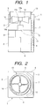
- FIG. 1 is a side view showing the construction of an outdoor unit of an air-conditioning system embodying the present invention
- FIG. 2 is a plan view of the outdoor unit of FIG. 1
- FIG. 3 is an enlarged view of a propeller fan section of FIG. 1
- FIG. 4 is a perspective view of a bell mouth of FIG. 1
- FIG. 5 is an enlarged sectional view of portion B of FIG. 4.
- the numeral 1 indicates a housing of the outdoor unit constructed of a front panel 2, a rear panel 3, left and right side panels 4, a top panel 5 and a bottom plate 6.
- the numeral 7 indicates a heat exchanger which is located close to the rear panel 3 of the housing 1.
- the numeral 8 indicates a machine compartment which is located close to the front panel 2, incorporating mechanical devices such as a compressor.
- the numeral 9 indicates an electric element box which is located above the machine compartment 8, incorporating electric devices such as a controller.
- the numeral 10 indicates a motor support which is fixed to a specific position inside the housing 1.
- the numeral 11 indicates a motor fixed to the motor support 10.
- the numeral 12 indicates a propeller fan which is fixed to a rotary shaft 11a of the motor 11.
- Indicated by the numeral 13 is the bell mouth which includes a guide portion 13a for guiding air blown out from the propeller fan 12 and a damping portion 14 projecting upstream from the guide portion along its axial direction, in which the guide portion 13a and the damping portion 14 are formed into a single piece as shown in FIG. 4.
- the bell mouth 13 is fixed to an air outlet of the top panel 5 in such a way that the guide portion 13a surrounds an outflow side of the propeller fan 12 with a specified clearance provided between the guide portion 13a and the propeller fan 12, and the damping portion 14 is located between the front panel 2 and the propeller fan 12.
- An end surface 14a of the damping portion 14 at its upstream side is chamfered into an arc shape in cross section as shown in FIG. 5.
- the propeller fan 12 rotates when the motor 11 is run, and air in the housing 1 is blown out through the bell mouth 13. Then, a negative pressure is developed inside the housing 1 and, as a consequence, outside air flows into the housing 1 through the heat exchanger 7.
- the propeller fan 12 draws in the air just from its axial direction and, therefore, pressure variations (pressure pulsation) that cause the front panel 2 to vibrate in the direction of arrow A shown in FIG. 3 occur on an inflow side of the propeller fan 12.
- pressure variations pressure pulsation
- the bell mouth 13 and the damping portion 14 may be one-piece formed using a metallic or synthetic resin material.
- the bell mouth 13 and the damping portion 14 may be formed of metallic and synthetic resin materials, respectively.
- FIG. 6 is a plan view showing an outdoor unit of an air-conditioning system according to a second embodiment of the invention.
- elements identical to those shown in FIG. 2 are designated by the same reference numerals.
- a heat exchanger 7 is mounted along a rear panel 3 and one side panel 4 as illustrated, the clearance between the outer periphery of a propeller fan 12 and a front panel 2 and the other side panel 4 decreases.
- a bell mouth 13 is installed such that a damping portion 14 is positioned in the clearance between them to thereby reduce vibration of the outdoor unit caused by pressure pulsation.
- FIG. 7 is a plan view showing an outdoor unit of an air-conditioning system according to a third embodiment of the invention.
- FIG. 8 is a plan view showing an outdoor unit of an air-conditioning system according to a fourth embodiment of the invention.
- FIG. 9 is a perspective view of the bell mouth according to the second embodiment of the invention.
- the numeral 13 indicates the bell mouth which includes a guide portion 13a for guiding air blown out from the propeller fan and the damping portion 14 projecting upstream from the guide portion 13a along its axial direction, in which the guide portion 13a and the damping portion 14 are formed into a single piece and a far end of the damping portion 14 at its upstream side is cut into an arc shape.
- FIG. 10 is a perspective view of the bell mouth according to the third embodiment of the invention.
- the numeral 13 indicates the bell mouth which includes a guide portion 13a for guiding air blown out from the propeller fan and the damping portion 14 projecting in a semicircular shape upstream from the guide portion 13a along its axial direction, in which the guide portion 13a and the damping portion 14 are formed into a single piece.
- FIG. 11 is a perspective view of the bell mouth according to the fourth embodiment of the invention.
- the numeral 13 indicates the bell mouth which includes a guide portion 13a for guiding air blown out from the propeller fan and the damping portion 14 projecting upstream from the guide portion 13a along its axial direction, the width of the damping portion 14 decreasing toward the upstream side, in which the guide portion 13a and the damping portion 14 are formed into a single piece.
- FIG. 12 is a perspective view of a bell mouth according to a fifth embodiment of the invention.
- the numeral 13 indicates the bell mouth which includes a guide portion 13a for guiding air blown out from a propeller fan and a damping portion 14 projecting upstream from the guide portion 13a along its axial direction, in which the damping portion 14 is cut into an arc shape in such a way that the width of the damping portion 14 decreases toward the upstream side, and the guide portion 13a and the damping portion 14 are formed into a single piece.
- FIGS. 9, 10, 11 and 12 make it possible to reduce the cost of materials without impairing the damping effect when the position where pressure pulsation occurs exists close to the guide portion 13a due to the relationship between the positions of the propeller fan and the bell mouth 13 along the axial direction.
- FIG. 13 is a perspective view of a bell mouth according to a sixth embodiment of the invention.
- the numeral 13 indicates the bell mouth which includes a guide portion 13a for guiding air blown out from a propeller fan and a damping portion 14 projecting upstream from the guide portion 13a along its axial direction, in which the damping portion 14 is cut at its connecting areas adjoining the guide portion 13a in such a way that the width of the damping portion 14 increases toward the upstream side, and the guide portion 13a and the damping portion 14 are formed into a single piece.
- FIG. 14 is a perspective view of a bell mouth according to a seventh embodiment of the invention.
- the numeral 13 indicates the bell mouth which includes a guide portion 13a for guiding air blown out from a propeller fan and a damping portion 14 projecting upstream from the guide portion 13a along its axial direction, in which the damping portion 14 is cut into an arc shape at its connecting areas adjoining the guide portion 13a in such a way that the width of the damping portion 14 increases toward the upstream side, and the guide portion 13a and the damping portion 14 are formed into a single piece.
- FIGS. 13 and 14 make it possible to reduce the cost of materials without impairing the damping effect when the position where pressure pulsation occurs exists upstream side of the damping portion 14 due to the relationship between the positions of the propeller fan and the bell mouth 13 along the axial direction.
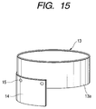
- FIG. 15 is a perspective view of a bell mouth according to an eighth embodiment of the invention.
- the numeral 13 indicates the bell mouth which includes a guide portion 13a for guiding air blown out from a propeller fan and a damping portion 14 which is formed separately from the guide portion 13a and is detachably joined to the guide portion 13a by fixing parts 15 like screws.
- FIG. 16 is a perspective view of a bell mouth according to a ninth embodiment of the invention.
- the numeral 13 indicates the bell mouth of which guide portion 13a and damping portion 14 are formed as single piece together with a top panel 5.
- FIG. 17 is a perspective view of a bell mouth according to a tenth embodiment of the invention.
- the numeral 13 indicates the bell mouth of which guide portion 13a and a top panel 5 is formed as single piece while a damping portion 14 is formed as a separate element and detachably joined to the guide portion 13a by fixing parts 15.
- the present invention makes it possible to decrease vibration of an outdoor unit of an air-conditioning system due to pressure pulsation which is produced by a propeller fan when the physical size of the outdoor unit is reduced.
Landscapes
- Engineering & Computer Science (AREA)
- Chemical & Material Sciences (AREA)
- Combustion & Propulsion (AREA)
- Mechanical Engineering (AREA)
- General Engineering & Computer Science (AREA)
- Other Air-Conditioning Systems (AREA)
Applications Claiming Priority (2)
| Application Number | Priority Date | Filing Date | Title |
|---|---|---|---|
| JP34131997 | 1997-12-11 | ||
| JP34131997A JPH11173605A (ja) | 1997-12-11 | 1997-12-11 | 空気調和機の室外ユニット |
Publications (2)
| Publication Number | Publication Date |
|---|---|
| EP0922911A2 true EP0922911A2 (de) | 1999-06-16 |
| EP0922911A3 EP0922911A3 (de) | 2001-06-20 |
Family
ID=18345147
Family Applications (1)
| Application Number | Title | Priority Date | Filing Date |
|---|---|---|---|
| EP98122718A Withdrawn EP0922911A3 (de) | 1997-12-11 | 1998-11-30 | Ausseneinheit für Klimaanlage |
Country Status (2)
| Country | Link |
|---|---|
| EP (1) | EP0922911A3 (de) |
| JP (1) | JPH11173605A (de) |
Cited By (7)
| Publication number | Priority date | Publication date | Assignee | Title |
|---|---|---|---|---|
| WO2001051859A1 (en) * | 2000-01-14 | 2001-07-19 | Toshiba Carrier Corporation | Outdoor unit of air conditioner |
| EP1577616A4 (de) * | 2002-11-05 | 2007-08-08 | Daikin Ind Ltd | Aussenaggregat eines kühlschrankes und e-geräteschrank des aussenaggregats |
| EP2085709A1 (de) * | 2008-01-30 | 2009-08-05 | LG Electronics Inc. | Klimaanlage |
| CN105526644A (zh) * | 2016-01-15 | 2016-04-27 | 珠海格力电器股份有限公司 | 一种空调器室外机 |
| EP3351861A1 (de) * | 2017-01-24 | 2018-07-25 | Vaillant GmbH | Luftwärmetauscher |
| EP3354995A1 (de) | 2017-01-30 | 2018-08-01 | Daikin applied Europe S.p.A. | Lüfter für temperaturaufbereitungssystem |
| EP4012278A1 (de) * | 2020-12-08 | 2022-06-15 | Robert Bosch GmbH | Wärmeübertragervorrichtung und verwendung einer wärmeübertragervorrichtung |
Families Citing this family (7)
| Publication number | Priority date | Publication date | Assignee | Title |
|---|---|---|---|---|
| KR20080051593A (ko) * | 2006-12-06 | 2008-06-11 | 삼성전자주식회사 | 공기조화기의 실외기 |
| US9062888B2 (en) | 2008-03-11 | 2015-06-23 | Mitsubishi Electric Corporation | Air conditioner |
| JP5812572B2 (ja) * | 2010-03-24 | 2015-11-17 | 三菱電機株式会社 | 軸流送風機およびこの軸流送風機を用いた空気調和機の室外機 |
| CN102853482A (zh) * | 2011-06-29 | 2013-01-02 | 日立空调·家用电器株式会社 | 一种分体式空调器室外机 |
| JP6283194B2 (ja) * | 2013-10-21 | 2018-02-21 | 日立ジョンソンコントロールズ空調株式会社 | 空気調和機の室外機 |
| US10982863B2 (en) * | 2018-04-10 | 2021-04-20 | Carrier Corporation | HVAC fan inlet |
| JP7100507B2 (ja) * | 2018-06-22 | 2022-07-13 | 三菱重工サーマルシステムズ株式会社 | 室外機ユニット |
Citations (1)
| Publication number | Priority date | Publication date | Assignee | Title |
|---|---|---|---|---|
| JPH03255829A (ja) | 1990-03-07 | 1991-11-14 | Hitachi Ltd | 空気調和機用室外ユニット |
Family Cites Families (3)
| Publication number | Priority date | Publication date | Assignee | Title |
|---|---|---|---|---|
| GB2240588B (en) * | 1990-01-31 | 1994-08-03 | Toshiba Kk | Ventilating fan |
| JPH07174363A (ja) * | 1993-12-20 | 1995-07-14 | Matsushita Refrig Co Ltd | 空気調和機の室外機 |
| JPH09137970A (ja) * | 1995-11-15 | 1997-05-27 | Matsushita Refrig Co Ltd | 空気調和機の室外機 |
-
1997
- 1997-12-11 JP JP34131997A patent/JPH11173605A/ja active Pending
-
1998
- 1998-11-30 EP EP98122718A patent/EP0922911A3/de not_active Withdrawn
Patent Citations (1)
| Publication number | Priority date | Publication date | Assignee | Title |
|---|---|---|---|---|
| JPH03255829A (ja) | 1990-03-07 | 1991-11-14 | Hitachi Ltd | 空気調和機用室外ユニット |
Cited By (9)
| Publication number | Priority date | Publication date | Assignee | Title |
|---|---|---|---|---|
| WO2001051859A1 (en) * | 2000-01-14 | 2001-07-19 | Toshiba Carrier Corporation | Outdoor unit of air conditioner |
| US6591628B2 (en) | 2000-01-14 | 2003-07-15 | Toshiba Carrier Corporation | Outdoor unit of air conditioner |
| EP1577616A4 (de) * | 2002-11-05 | 2007-08-08 | Daikin Ind Ltd | Aussenaggregat eines kühlschrankes und e-geräteschrank des aussenaggregats |
| US7363768B2 (en) | 2002-11-05 | 2008-04-29 | Daikin Industries, Ltd. | Outdoor unit of refrigerator, and electrical equipment box of outdoor unit |
| EP2085709A1 (de) * | 2008-01-30 | 2009-08-05 | LG Electronics Inc. | Klimaanlage |
| CN105526644A (zh) * | 2016-01-15 | 2016-04-27 | 珠海格力电器股份有限公司 | 一种空调器室外机 |
| EP3351861A1 (de) * | 2017-01-24 | 2018-07-25 | Vaillant GmbH | Luftwärmetauscher |
| EP3354995A1 (de) | 2017-01-30 | 2018-08-01 | Daikin applied Europe S.p.A. | Lüfter für temperaturaufbereitungssystem |
| EP4012278A1 (de) * | 2020-12-08 | 2022-06-15 | Robert Bosch GmbH | Wärmeübertragervorrichtung und verwendung einer wärmeübertragervorrichtung |
Also Published As
| Publication number | Publication date |
|---|---|
| JPH11173605A (ja) | 1999-07-02 |
| EP0922911A3 (de) | 2001-06-20 |
Similar Documents
| Publication | Publication Date | Title |
|---|---|---|
| US8240997B2 (en) | Centrifugal impeller and centrifugal blower using the centrifugal impeller | |
| EP2390590A2 (de) | In die Decke eingebaute Klimaanlagenvorrichtung | |
| EP1050720B1 (de) | Klimaanlage | |
| AU2020289818B2 (en) | Propeller fan, air-sending device, and refrigeration cycle device | |
| EP2848817B1 (de) | Zentrifugalgebläse und Klimaanlage | |
| JPH11173605A (ja) | 空気調和機の室外ユニット | |
| JPWO2017051521A1 (ja) | 温度調和ユニット、温度調和システム、車両 | |
| JP2010124534A (ja) | 電動機用斜流ファンと該斜流ファンを備えた電動機 | |
| CN105179273B (zh) | 一种空气调节设备 | |
| JP2018084232A (ja) | 送風装置及びこれを用いた空気調和機用室外機 | |
| JP2003214658A (ja) | 空気調和機の室外機 | |
| JP2002054594A (ja) | 遠心ファン | |
| WO2017042865A1 (ja) | 空気調和機の室外機 | |
| US4633680A (en) | Double wall condenser orifice | |
| JP3141663B2 (ja) | 空気調和機の室内ユニット | |
| JP2007205268A (ja) | 遠心ファン | |
| JP5465021B2 (ja) | ターボファン及びこのターボファンを備えた空気調和機 | |
| US11852168B2 (en) | Fan hub isolator | |
| CN109945312A (zh) | 空调室内机的风道部件及空调室内机 | |
| JPH06331178A (ja) | 室外機 | |
| JP4317676B2 (ja) | 空気調和機用ターボファン | |
| JP2011163564A (ja) | 空気調和機の室内ユニット | |
| JP2007051790A (ja) | 空調用室内機 | |
| JP7312934B2 (ja) | ターボファン | |
| JP2006029164A (ja) | 遠心送風機および該遠心送風機を備えた空気調和装置 |
Legal Events
| Date | Code | Title | Description |
|---|---|---|---|
| PUAI | Public reference made under article 153(3) epc to a published international application that has entered the european phase |
Free format text: ORIGINAL CODE: 0009012 |
|
| 17P | Request for examination filed |
Effective date: 19981130 |
|
| AK | Designated contracting states |
Kind code of ref document: A2 Designated state(s): DE ES GB |
|
| AX | Request for extension of the european patent |
Free format text: AL;LT;LV;MK;RO;SI |
|
| PUAL | Search report despatched |
Free format text: ORIGINAL CODE: 0009013 |
|
| AK | Designated contracting states |
Kind code of ref document: A3 Designated state(s): AT BE CH CY DE DK ES FI FR GB GR IE IT LI LU MC NL PT SE |
|
| AX | Request for extension of the european patent |
Free format text: AL;LT;LV;MK;RO;SI |
|
| RIC1 | Information provided on ipc code assigned before grant |
Free format text: 7F 24F 1/00 A, 7F 24F 13/24 B |
|
| AKX | Designation fees paid |
Free format text: DE ES GB |
|
| 17Q | First examination report despatched |
Effective date: 20040309 |
|
| STAA | Information on the status of an ep patent application or granted ep patent |
Free format text: STATUS: THE APPLICATION HAS BEEN WITHDRAWN |
|
| 18W | Application withdrawn |
Effective date: 20040609 |