EP0922921A2 - Dampfbeheizte Walze, insbesondere für Wellpappemaschinen - Google Patents
Dampfbeheizte Walze, insbesondere für Wellpappemaschinen Download PDFInfo
- Publication number
- EP0922921A2 EP0922921A2 EP98120897A EP98120897A EP0922921A2 EP 0922921 A2 EP0922921 A2 EP 0922921A2 EP 98120897 A EP98120897 A EP 98120897A EP 98120897 A EP98120897 A EP 98120897A EP 0922921 A2 EP0922921 A2 EP 0922921A2
- Authority
- EP
- European Patent Office
- Prior art keywords
- roller
- tube
- support tube
- suction opening
- roller according
- Prior art date
- Legal status (The legal status is an assumption and is not a legal conclusion. Google has not performed a legal analysis and makes no representation as to the accuracy of the status listed.)
- Granted
Links
Images


Classifications
-
- B—PERFORMING OPERATIONS; TRANSPORTING
- B31—MAKING ARTICLES OF PAPER, CARDBOARD OR MATERIAL WORKED IN A MANNER ANALOGOUS TO PAPER; WORKING PAPER, CARDBOARD OR MATERIAL WORKED IN A MANNER ANALOGOUS TO PAPER
- B31F—MECHANICAL WORKING OR DEFORMATION OF PAPER, CARDBOARD OR MATERIAL WORKED IN A MANNER ANALOGOUS TO PAPER
- B31F1/00—Mechanical deformation without removing material, e.g. in combination with laminating
- B31F1/20—Corrugating; Corrugating combined with laminating to other layers
- B31F1/24—Making webs in which the channel of each corrugation is transverse to the web feed
- B31F1/26—Making webs in which the channel of each corrugation is transverse to the web feed by interengaging toothed cylinders cylinder constructions
- B31F1/28—Making webs in which the channel of each corrugation is transverse to the web feed by interengaging toothed cylinders cylinder constructions combined with uniting the corrugated webs to flat webs ; Making double-faced corrugated cardboard
- B31F1/2845—Details, e.g. provisions for drying, moistening, pressing
- B31F1/285—Heating or drying equipment
-
- F—MECHANICAL ENGINEERING; LIGHTING; HEATING; WEAPONS; BLASTING
- F28—HEAT EXCHANGE IN GENERAL
- F28F—DETAILS OF HEAT-EXCHANGE AND HEAT-TRANSFER APPARATUS, OF GENERAL APPLICATION
- F28F5/00—Elements specially adapted for movement
- F28F5/02—Rotary drums or rollers
Definitions
- the invention relates to a steam-heated roller, in particular for corrugated cardboard machines with those specified in the preamble of claim 1 Characteristics.
- Such steam-heated rollers can be used for a wide variety of purposes be used for the processing of web goods.
- preheating rollers or so-called "corrugated rollers" for corrugated cardboard machines to call With such corrugated rollers, a paper web is used by working together with a counter corrugating roller in the typical Brought wave form, as can be observed with corrugated cardboard material.
- the corrugating roller is known to support the corrugation of the paper web heated in temperature ranges from 180 ° to 200 ° C. this happens with saturated steam, which is in the interior of the hollow cylindrical roller body is introduced. Support the preheating rollers also mentioned the paper heating in front of the corrugating roller.
- Siphon tube a so-called "Siphon tube” known. It is a pressure-tight through one of the trunnions, statically arranged, bent pipe, that runs right up to the roller base and there is a suction opening forms. Since the siphon pipe passed through the journal and in must not be installed visible interior of the roller body is Now adjust the suction opening as close as possible to the Inner wall of the jacket extremely problematic. The smallest possible distance between the suction opening and the roller base is logical Therefore, in order to remove the condensate as completely as possible. However, the siphon tube is now mounted so that it is on the roller base abuts, it can lead to a deformation of the siphon tube and grinding come in the area of the suction opening.
- the invention has for its object the mountability of the siphon tube, improve its adjustability and pressure-tight implementation.
- the object is achieved by that the siphon tube from an outer, rigid support tube and one inside there is a slidably mounted, flexible insert tube. Through a relative shift The distance from the suction opening is from insert tube to support tube adjustable to the roller base.
- outer support tube installed in a certain, uncritical mounting position can be.
- the adjustment can be carried out by means of the flexible insert tube take place, the z. B. up to the stop pushed onto the roller base and then a short distance - Just the desired distance between the suction opening and Roller base - can be withdrawn.
- the support tube remains firm in its position, with which a particularly tight implementation by the rotatable bearing pin can be achieved.
- Preferred embodiments of the insert tube see its design as a corrugated metal hose. This material is for use well suited under saturated steam conditions, but shows the necessary ones Flexibility in the bending direction and invariability in length in the longitudinal direction.
- the adjustability of the suction opening is further improved in that the insert tube at its inner end with a telescopic telescope in the support tube sliding nozzle is provided as another preferred Embodiment provides.
- the end of the support tube can be a corresponding one Have a chamfer so that the opening is at the position angle the longitudinal axis is adapted to the end of the support tube.
- the suction opening can be adjusted so that all around uniform minimum distance is adjustable. Otherwise, the maximum angle limits the longitudinal axis of the support tube at its end the bending radius of the Support tube, because of the feasibility of a corresponding Opening in the bearing journal must not become too small.
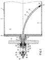
- a preheating roller as in a Corrugated cardboard machine is used, a roll body 1 with a roll shell 2 and on the front openings welded roller flanges 3 on.
- the roller flanges 3 with journals 4 are central provided in a roller frame 5 with roller bearings for rotatable storage of the roller body 2 sit.
- the roller interior 6 is not in with saturated steam for heating the roller body 1 acted upon.
- the steam is e.g. B. introduced through the journal 4, why the outside of the siphon tube 8 to be explained Annulus is used.
- the aforementioned siphon tube 8 is provided, which is pressure-tight by the Journal 4 inserted into the roller interior 6 and through his slightly curved course (see Fig. 1) ends just before the roller base 7.
- the siphon tube 8 consists of a outer, rigid support tube 9 in which a flexible metal corrugated hose 10 is slidably mounted.
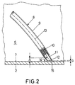
- This corrugated hose 10 ends before the opening of the support tube 9 and is provided at its end with a nozzle 11, which is telescopically displaceable in the support tube 9.
- the support tube 9 ends with a distance A of a few centimeters above the roller base 7 and is therefore uncritical in its assembly and adjustment.
- the gap to Roll base 7 is bridged by the nozzle 11, the opening on free end forms the suction opening 12 of the siphon tube arrangement 8.
- the support tube 9 is arcuate in this way trained that its longitudinal axis 13 at its roller inner end occupies an acute angle 14 of almost 60 ° to the roller base 7.
- the suction opening 12 is in one of these Angle 14 corresponding manner beveled, so that from the front edge 15 of the nozzle 11 spanned plane parallel to that for this Purpose as the roller base to be considered essentially flat.
- the bending profile of the support tube 9 is dimensioned so that the Support tube 9 through the through opening provided centrally in the journal 4 16 can be threaded through.
- FIG. 3 the outer end 31 of the support tube 9 is now in one Mounting flange 32 welded position recognizable. This mounting flange 32 is via mounting screws 33 with an insert 34 in the sealing head 21 connected. This insert 34 holds the support tube 9 over a certain Length to provide adequate support.
- the mounting flange 32 has a receptacle 35 on its outside a stuffing box 36, which can be acted upon by a clamping ring 37 is.
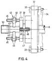
- the bushing is 38 provided with an adjusting device 42, with the help of which Bushing 38 and therefore the corrugated hose 10 and the nozzle 11 are displaceable in the longitudinal direction relative to the support tube 9.
- This adjustment device 42 sees two diametrically protruding from the bushing 38 Arms 43 in front, each with a passage opening 44 for threaded bolts 45 are provided. The latter are opposite on the clamping ring 37 fixed the threaded bolt 41 offset positions. On the threaded bolt 45 sit on both sides of the arms 43 fixing nuts 46, so that the in Fig. 4 shown position of the bushing 38 is fixed. Should now brought the suction opening 12 closer to the roller base 7 only the inner fixing nuts 46 (on the right in FIG.
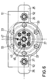
- an indexing device 47 in the form of an index pin 48 seated on the mounting flange 32 intended. This engages in a receiving opening 49 on the clamping ring 37 one, so that the corrugated hose 10 is not twisted in any way by 180 ° Location can be installed.
Landscapes
- Engineering & Computer Science (AREA)
- Mechanical Engineering (AREA)
- Physics & Mathematics (AREA)
- Thermal Sciences (AREA)
- General Engineering & Computer Science (AREA)
- Paper (AREA)
- Machines For Manufacturing Corrugated Board In Mechanical Paper-Making Processes (AREA)
Abstract
Description
- Fig. 1
- einen vertikalen Axialschnitt durch eine Vorheizwalze einer Wellpappemaschine,
- Fig. 2
- eine teilweise geschnittene Darstellung des inneren Ende des Syphonrohres in seiner Montagestellung über dem Grund der Walze gemäß Fig. 1,
- Fig. 3
- eine teilweise geschnittene Seitenansicht des das Syphonrohr haltenden Dichtkopfes der Walze gemäß Fig. 1,
- Fig. 4
- eine gegenüber der Schnittdarstellung nach Fig. 3 um 90° gedrehte Seitenansicht des Dichtkopfes,
- Fig. 5
- eine Seitenansicht des Dichtkopfes analog Fig. 3 mit geänderten Teilschnitten, und
- Fig. 6
- einer Ansicht aus Pfeilrichtung VI. nach Fig. 5.
Claims (8)
- Dampfbeheizte Walze, insbesondere für Wellpappemaschinen miteinem drehbaren Walzenkörper (1),einem zentrischen Lagerzapfen (4) am Ende eines jeden Walzenkörpers (1) zur drehbaren Lagerung des Walzenkörpers (1),einem druckdicht durch einen der Legerzapfen (4) geführten, statischen Syphonrohr (8), das einen außerhalb des Lagerzapfens (4) gelegenen Anschluß (50) und eine am Walzengrund (7) angeordnete Absaugöffnung (12) aufweist,
dadurch gekennzeichnet, daßdas Syphonrohr (8) aus einem äußeren, starren Stützrohr (9) und einem darin verschiebbar gelagerten, flexiblen Einsatzrohr (10) besteht, unddurch Relativverschiebung von Einsatzrohr (10) zu Stützrohr (9) der Abstand (a) der Absaugöffnung (12) zum Walzengrund (7) einstellbar ist. - Walze nach Anspruch 1, dadurch gekennzeichnet, daß das Einsatzrohr aus einem Metall-Wellschlauch (10) gebildet ist.
- Walze nach Anspruch 1 oder 2, dadurch gekennzeichnet, daß das Einsatzrohr (10) an seinem walzeninneren Ende mit einem im Stützrohr (9) teleskopartig verschiebbaren Stutzen (11) versehen ist.
- Walze nach Anspruch 3, dadurch gekennzeichnet, daß das Stützrohr (9) derart bogenförmig in den Walzeninnenraum (6) hinein verläuft, daß seine Längsachse (13) an seinem Ende einen spitzen Winkel (14) von maximal 60° zum Walzengrund (7) einnimmt.
- Walze nach Anspruch 3 und 4, dadurch gekennzeichnet, daß der Stutzen (11) eine dem Winkel (14) des Stützrohrendes entsprechend abgeschrägte Absaugöffnung (12) aufweist.
- Walze nach einem der Ansprüche 1 bis 5, dadurch gekennzeichnet, daß das Einsatzrohr (10) an seinem äußeren Ende mit einem Durchführungsstutzen (38) versehen ist, der über eine Dichtungspackung (36) druckdicht aus dem Stützrohr (9) herausgeführt ist.
- Walze nach Anspruch 6, dadurch gekennzeichnet, daß am Durchführungsstutzen (38) eine Verstelleinrichtung (42) zur Relativverschiebung von Einsatzrohr (10) zu Stützrohr (9) angreift.
- Walze nach Anspruch 6 oder 7, dadurch gekennzeichnet, daß ein Halter (37) für die Verstelleinrichtung (41) durch eine Indexiereinrichtung (47) in einer definierten Drehstellung um die Längsachse (13) des Stützrohres (9) montierbar ist.
Applications Claiming Priority (2)
| Application Number | Priority Date | Filing Date | Title |
|---|---|---|---|
| DE19755045A DE19755045A1 (de) | 1997-12-11 | 1997-12-11 | Dampfbeheizte Walze, insbesondere für Wellpappenmaschinen |
| DE19755045 | 1997-12-11 |
Publications (3)
| Publication Number | Publication Date |
|---|---|
| EP0922921A2 true EP0922921A2 (de) | 1999-06-16 |
| EP0922921A3 EP0922921A3 (de) | 2000-06-07 |
| EP0922921B1 EP0922921B1 (de) | 2003-02-05 |
Family
ID=7851548
Family Applications (1)
| Application Number | Title | Priority Date | Filing Date |
|---|---|---|---|
| EP98120897A Expired - Lifetime EP0922921B1 (de) | 1997-12-11 | 1998-11-04 | Dampfbeheizte Walze, insbesondere für Wellpappemaschinen |
Country Status (2)
| Country | Link |
|---|---|
| EP (1) | EP0922921B1 (de) |
| DE (2) | DE19755045A1 (de) |
Cited By (2)
| Publication number | Priority date | Publication date | Assignee | Title |
|---|---|---|---|---|
| EP1419879A1 (de) * | 2002-11-15 | 2004-05-19 | Mitsubishi Heavy Industries, Ltd. | Beheizte Walze für eine Wellenpappemaschine |
| US8523747B2 (en) | 2009-04-07 | 2013-09-03 | BHS Corrugated Maschinen—und Anlagenbau GmbH | Hollow roller which can be heated with steam |
Families Citing this family (2)
| Publication number | Priority date | Publication date | Assignee | Title |
|---|---|---|---|---|
| ITMI20120507A1 (it) * | 2012-03-29 | 2013-09-30 | Bp Agnati S R L | Gruppo e procedimento di lavorazione di cartone ondulato |
| EP2792478B1 (de) * | 2013-04-19 | 2019-03-20 | BP Agnati S.r.L. | Anordnung und Verfahren für die Herstellung von Wellpappe |
Family Cites Families (6)
| Publication number | Priority date | Publication date | Assignee | Title |
|---|---|---|---|---|
| DE398611C (de) * | 1923-10-13 | 1924-07-17 | Fried Krupp Akt Ges Grusonwerk | Heizvorrichtung fuer Hohlwalzen |
| DE2553447A1 (de) * | 1975-11-28 | 1977-06-02 | Kleinewefers Ind Co Gmbh | Syphon-kniegelenk |
| GB8824808D0 (en) * | 1988-10-22 | 1988-11-30 | Simon Container Mach Ltd | Heated roll |
| US5109612A (en) * | 1990-12-06 | 1992-05-05 | The Johnson Corporation | Aspirated syphon shoe |
| US5533569A (en) * | 1995-04-24 | 1996-07-09 | The Johnson Corporation | Stationary syphon system for rotating heat exchanger rolls |
| AU1462297A (en) * | 1995-12-11 | 1997-07-03 | Reijo K. Salminen | Processing roll apparatus and method |
-
1997
- 1997-12-11 DE DE19755045A patent/DE19755045A1/de not_active Withdrawn
-
1998
- 1998-11-04 EP EP98120897A patent/EP0922921B1/de not_active Expired - Lifetime
- 1998-11-04 DE DE59807112T patent/DE59807112D1/de not_active Expired - Fee Related
Cited By (2)
| Publication number | Priority date | Publication date | Assignee | Title |
|---|---|---|---|---|
| EP1419879A1 (de) * | 2002-11-15 | 2004-05-19 | Mitsubishi Heavy Industries, Ltd. | Beheizte Walze für eine Wellenpappemaschine |
| US8523747B2 (en) | 2009-04-07 | 2013-09-03 | BHS Corrugated Maschinen—und Anlagenbau GmbH | Hollow roller which can be heated with steam |
Also Published As
| Publication number | Publication date |
|---|---|
| EP0922921B1 (de) | 2003-02-05 |
| DE19755045A1 (de) | 1999-06-17 |
| DE59807112D1 (de) | 2003-03-13 |
| EP0922921A3 (de) | 2000-06-07 |
Similar Documents
| Publication | Publication Date | Title |
|---|---|---|
| DE2650937A1 (de) | Kaeltemaschine mit federnd in einer kapsel gehaltenem motorverdichter | |
| DE202014101342U1 (de) | Roboterarm und Montageset | |
| DE3439090C2 (de) | Zylinder für bahnförmiges Material verarbeitende Maschinen | |
| DE2526946B2 (de) | Rohrklemme | |
| EP0274090B1 (de) | Dichtung | |
| DE102011056040A1 (de) | Vorrichtung zum Ablängen von Wellrohren | |
| DE3410046A1 (de) | Abstreifvorrichtung fuer foerderbaender | |
| DE19642024B4 (de) | Rollbalg-Gasfeder mit einem Außenstützteil | |
| DE3117850A1 (de) | Spanneinrichtung an werkzeugmaschinen mit einem umlaufenden spannzylinder und mit einer kontrolleinrichtung fuer die axialverschiebungen eines im spannzylinder mitumlaufend angeordneten spannkolbens | |
| EP0922921B1 (de) | Dampfbeheizte Walze, insbesondere für Wellpappemaschinen | |
| DE3743642C2 (de) | ||
| EP0913521A2 (de) | Heiz- und/oder kühlbarer Zylinder | |
| DE69714757T2 (de) | Entnahmewalze, breitstreckwalze oder dergleichen für bahnförmiges materal | |
| WO1995001477A1 (de) | Vorrichtung zum abführen von kondensat aus einem gerillten trockenzylinder mittels kondensatabzugsrohren | |
| DE19910125C2 (de) | Vorrichtung zur Kondensatableitung aus dampfbeheizten Walzen | |
| WO2013029989A1 (de) | Vorrichtung zum halten von schaberklingen | |
| DE4408624A1 (de) | Elektromaschine | |
| DE953676C (de) | Umlaufende Gelenkverbindung | |
| DE4319288C2 (de) | Verbindungsschelle | |
| DE2443052C2 (de) | Drehgelenk für eine elektrische Steckvorrichtung | |
| DE4223900A1 (de) | Zugwalze | |
| DE2449651C3 (de) | Vorrichtung zum Absaugen von Kondensat oder anderen Medien von der Innenwand einer umlaufenden Walze | |
| DE4018390A1 (de) | Heizeinrichtung an cigarettenmaschinen | |
| DE19808655A1 (de) | Temperaturfühleranordnung insbesondere für Wärmezähler | |
| DE3114731A1 (de) | Zylinder fuer bahnfoermiges material verarbeitende maschinen |
Legal Events
| Date | Code | Title | Description |
|---|---|---|---|
| PUAI | Public reference made under article 153(3) epc to a published international application that has entered the european phase |
Free format text: ORIGINAL CODE: 0009012 |
|
| AK | Designated contracting states |
Kind code of ref document: A2 Designated state(s): DE FR GB IT |
|
| AX | Request for extension of the european patent |
Free format text: AL;LT;LV;MK;RO;SI |
|
| PUAL | Search report despatched |
Free format text: ORIGINAL CODE: 0009013 |
|
| AK | Designated contracting states |
Kind code of ref document: A3 Designated state(s): AT BE CH CY DE DK ES FI FR GB GR IE IT LI LU MC NL PT SE |
|
| AX | Request for extension of the european patent |
Free format text: AL;LT;LV;MK;RO;SI |
|
| 17P | Request for examination filed |
Effective date: 20000518 |
|
| AKX | Designation fees paid |
Free format text: DE FR GB IT |
|
| GRAG | Despatch of communication of intention to grant |
Free format text: ORIGINAL CODE: EPIDOS AGRA |
|
| 17Q | First examination report despatched |
Effective date: 20020311 |
|
| GRAG | Despatch of communication of intention to grant |
Free format text: ORIGINAL CODE: EPIDOS AGRA |
|
| GRAH | Despatch of communication of intention to grant a patent |
Free format text: ORIGINAL CODE: EPIDOS IGRA |
|
| GRAH | Despatch of communication of intention to grant a patent |
Free format text: ORIGINAL CODE: EPIDOS IGRA |
|
| GRAA | (expected) grant |
Free format text: ORIGINAL CODE: 0009210 |
|
| AK | Designated contracting states |
Designated state(s): DE FR GB IT |
|
| REG | Reference to a national code |
Ref country code: GB Ref legal event code: FG4D Free format text: NOT ENGLISH |
|
| REF | Corresponds to: |
Ref document number: 59807112 Country of ref document: DE Date of ref document: 20030313 Kind code of ref document: P |
|
| GBT | Gb: translation of ep patent filed (gb section 77(6)(a)/1977) | ||
| ET | Fr: translation filed | ||
| PLBE | No opposition filed within time limit |
Free format text: ORIGINAL CODE: 0009261 |
|
| STAA | Information on the status of an ep patent application or granted ep patent |
Free format text: STATUS: NO OPPOSITION FILED WITHIN TIME LIMIT |
|
| 26N | No opposition filed |
Effective date: 20031106 |
|
| PGFP | Annual fee paid to national office [announced via postgrant information from national office to epo] |
Ref country code: FR Payment date: 20061117 Year of fee payment: 9 |
|
| PGFP | Annual fee paid to national office [announced via postgrant information from national office to epo] |
Ref country code: GB Payment date: 20061123 Year of fee payment: 9 |
|
| PGFP | Annual fee paid to national office [announced via postgrant information from national office to epo] |
Ref country code: IT Payment date: 20061130 Year of fee payment: 9 |
|
| PGFP | Annual fee paid to national office [announced via postgrant information from national office to epo] |
Ref country code: DE Payment date: 20061227 Year of fee payment: 9 |
|
| GBPC | Gb: european patent ceased through non-payment of renewal fee |
Effective date: 20071104 |
|
| PG25 | Lapsed in a contracting state [announced via postgrant information from national office to epo] |
Ref country code: DE Free format text: LAPSE BECAUSE OF NON-PAYMENT OF DUE FEES Effective date: 20080603 |
|
| REG | Reference to a national code |
Ref country code: FR Ref legal event code: ST Effective date: 20080930 |
|
| PG25 | Lapsed in a contracting state [announced via postgrant information from national office to epo] |
Ref country code: GB Free format text: LAPSE BECAUSE OF NON-PAYMENT OF DUE FEES Effective date: 20071104 |
|
| PG25 | Lapsed in a contracting state [announced via postgrant information from national office to epo] |
Ref country code: FR Free format text: LAPSE BECAUSE OF NON-PAYMENT OF DUE FEES Effective date: 20071130 |
|
| PG25 | Lapsed in a contracting state [announced via postgrant information from national office to epo] |
Ref country code: IT Free format text: LAPSE BECAUSE OF NON-PAYMENT OF DUE FEES Effective date: 20071104 |