EP0922941A1 - Système de capteurs de débit du type distributeur - Google Patents
Système de capteurs de débit du type distributeur Download PDFInfo
- Publication number
- EP0922941A1 EP0922941A1 EP98309788A EP98309788A EP0922941A1 EP 0922941 A1 EP0922941 A1 EP 0922941A1 EP 98309788 A EP98309788 A EP 98309788A EP 98309788 A EP98309788 A EP 98309788A EP 0922941 A1 EP0922941 A1 EP 0922941A1
- Authority
- EP
- European Patent Office
- Prior art keywords
- input
- output
- flow
- manifold
- flow detector
- Prior art date
- Legal status (The legal status is an assumption and is not a legal conclusion. Google has not performed a legal analysis and makes no representation as to the accuracy of the status listed.)
- Granted
Links
- 239000012530 fluid Substances 0.000 claims abstract description 46
- 238000001514 detection method Methods 0.000 claims abstract description 12
- 230000000149 penetrating effect Effects 0.000 claims abstract description 6
- 238000005259 measurement Methods 0.000 abstract description 4
- 239000000843 powder Substances 0.000 description 4
- 238000009434 installation Methods 0.000 description 3
- 238000004519 manufacturing process Methods 0.000 description 3
- 230000001105 regulatory effect Effects 0.000 description 3
- 239000004065 semiconductor Substances 0.000 description 3
- 230000002093 peripheral effect Effects 0.000 description 2
- 238000011109 contamination Methods 0.000 description 1
Images

Classifications
-
- G—PHYSICS
- G01—MEASURING; TESTING
- G01F—MEASURING VOLUME, VOLUME FLOW, MASS FLOW OR LIQUID LEVEL; METERING BY VOLUME
- G01F1/00—Measuring the volume flow or mass flow of fluid or fluent solid material wherein the fluid passes through a meter in a continuous flow
- G01F1/68—Measuring the volume flow or mass flow of fluid or fluent solid material wherein the fluid passes through a meter in a continuous flow by using thermal effects
- G01F1/684—Structural arrangements; Mounting of elements, e.g. in relation to fluid flow
-
- F—MECHANICAL ENGINEERING; LIGHTING; HEATING; WEAPONS; BLASTING
- F15—FLUID-PRESSURE ACTUATORS; HYDRAULICS OR PNEUMATICS IN GENERAL
- F15B—SYSTEMS ACTING BY MEANS OF FLUIDS IN GENERAL; FLUID-PRESSURE ACTUATORS, e.g. SERVOMOTORS; DETAILS OF FLUID-PRESSURE SYSTEMS, NOT OTHERWISE PROVIDED FOR
- F15B13/00—Details of servomotor systems ; Valves for servomotor systems
- F15B13/02—Fluid distribution or supply devices characterised by their adaptation to the control of servomotors
- F15B13/06—Fluid distribution or supply devices characterised by their adaptation to the control of servomotors for use with two or more servomotors
- F15B13/08—Assemblies of units, each for the control of a single servomotor only
- F15B13/0803—Modular units
- F15B13/0832—Modular valves
- F15B13/0839—Stacked plate type valves
-
- F—MECHANICAL ENGINEERING; LIGHTING; HEATING; WEAPONS; BLASTING
- F15—FLUID-PRESSURE ACTUATORS; HYDRAULICS OR PNEUMATICS IN GENERAL
- F15B—SYSTEMS ACTING BY MEANS OF FLUIDS IN GENERAL; FLUID-PRESSURE ACTUATORS, e.g. SERVOMOTORS; DETAILS OF FLUID-PRESSURE SYSTEMS, NOT OTHERWISE PROVIDED FOR
- F15B13/00—Details of servomotor systems ; Valves for servomotor systems
- F15B13/02—Fluid distribution or supply devices characterised by their adaptation to the control of servomotors
- F15B13/06—Fluid distribution or supply devices characterised by their adaptation to the control of servomotors for use with two or more servomotors
- F15B13/08—Assemblies of units, each for the control of a single servomotor only
- F15B13/0803—Modular units
- F15B13/0807—Manifolds
- F15B13/0817—Multiblock manifolds
-
- F—MECHANICAL ENGINEERING; LIGHTING; HEATING; WEAPONS; BLASTING
- F15—FLUID-PRESSURE ACTUATORS; HYDRAULICS OR PNEUMATICS IN GENERAL
- F15B—SYSTEMS ACTING BY MEANS OF FLUIDS IN GENERAL; FLUID-PRESSURE ACTUATORS, e.g. SERVOMOTORS; DETAILS OF FLUID-PRESSURE SYSTEMS, NOT OTHERWISE PROVIDED FOR
- F15B13/00—Details of servomotor systems ; Valves for servomotor systems
- F15B13/02—Fluid distribution or supply devices characterised by their adaptation to the control of servomotors
- F15B13/06—Fluid distribution or supply devices characterised by their adaptation to the control of servomotors for use with two or more servomotors
- F15B13/08—Assemblies of units, each for the control of a single servomotor only
- F15B13/0803—Modular units
- F15B13/0846—Electrical details
- F15B13/0853—Electric circuit boards
-
- F—MECHANICAL ENGINEERING; LIGHTING; HEATING; WEAPONS; BLASTING
- F15—FLUID-PRESSURE ACTUATORS; HYDRAULICS OR PNEUMATICS IN GENERAL
- F15B—SYSTEMS ACTING BY MEANS OF FLUIDS IN GENERAL; FLUID-PRESSURE ACTUATORS, e.g. SERVOMOTORS; DETAILS OF FLUID-PRESSURE SYSTEMS, NOT OTHERWISE PROVIDED FOR
- F15B13/00—Details of servomotor systems ; Valves for servomotor systems
- F15B13/02—Fluid distribution or supply devices characterised by their adaptation to the control of servomotors
- F15B13/06—Fluid distribution or supply devices characterised by their adaptation to the control of servomotors for use with two or more servomotors
- F15B13/08—Assemblies of units, each for the control of a single servomotor only
- F15B13/0803—Modular units
- F15B13/0846—Electrical details
- F15B13/0857—Electrical connecting means, e.g. plugs, sockets
-
- F—MECHANICAL ENGINEERING; LIGHTING; HEATING; WEAPONS; BLASTING
- F15—FLUID-PRESSURE ACTUATORS; HYDRAULICS OR PNEUMATICS IN GENERAL
- F15B—SYSTEMS ACTING BY MEANS OF FLUIDS IN GENERAL; FLUID-PRESSURE ACTUATORS, e.g. SERVOMOTORS; DETAILS OF FLUID-PRESSURE SYSTEMS, NOT OTHERWISE PROVIDED FOR
- F15B13/00—Details of servomotor systems ; Valves for servomotor systems
- F15B13/02—Fluid distribution or supply devices characterised by their adaptation to the control of servomotors
- F15B13/06—Fluid distribution or supply devices characterised by their adaptation to the control of servomotors for use with two or more servomotors
- F15B13/08—Assemblies of units, each for the control of a single servomotor only
- F15B13/0803—Modular units
- F15B13/0846—Electrical details
- F15B13/086—Sensing means, e.g. pressure sensors
-
- G—PHYSICS
- G01—MEASURING; TESTING
- G01F—MEASURING VOLUME, VOLUME FLOW, MASS FLOW OR LIQUID LEVEL; METERING BY VOLUME
- G01F15/00—Details of, or accessories for, apparatus of groups G01F1/00 - G01F13/00 insofar as such details or appliances are not adapted to particular types of such apparatus
- G01F15/18—Supports or connecting means for meters
-
- Y—GENERAL TAGGING OF NEW TECHNOLOGICAL DEVELOPMENTS; GENERAL TAGGING OF CROSS-SECTIONAL TECHNOLOGIES SPANNING OVER SEVERAL SECTIONS OF THE IPC; TECHNICAL SUBJECTS COVERED BY FORMER USPC CROSS-REFERENCE ART COLLECTIONS [XRACs] AND DIGESTS
- Y10—TECHNICAL SUBJECTS COVERED BY FORMER USPC
- Y10T—TECHNICAL SUBJECTS COVERED BY FORMER US CLASSIFICATION
- Y10T137/00—Fluid handling
- Y10T137/8593—Systems
- Y10T137/877—With flow control means for branched passages
- Y10T137/87877—Single inlet with multiple distinctly valved outlets
-
- Y—GENERAL TAGGING OF NEW TECHNOLOGICAL DEVELOPMENTS; GENERAL TAGGING OF CROSS-SECTIONAL TECHNOLOGIES SPANNING OVER SEVERAL SECTIONS OF THE IPC; TECHNICAL SUBJECTS COVERED BY FORMER USPC CROSS-REFERENCE ART COLLECTIONS [XRACs] AND DIGESTS
- Y10—TECHNICAL SUBJECTS COVERED BY FORMER USPC
- Y10T—TECHNICAL SUBJECTS COVERED BY FORMER US CLASSIFICATION
- Y10T137/00—Fluid handling
- Y10T137/8593—Systems
- Y10T137/877—With flow control means for branched passages
- Y10T137/87885—Sectional block structure
Definitions
- the present invention relates to a manifold-type flow detector assembly that can be effectively used with semiconductor fabrication apparatuses and other such equipment which is maintained in a clean environment.
- a flow sensor for detecting the flow of a fluid flowing through a channel is generally either incorporated into fluid equipment or used as an independent device. If a flow sensor is used independently in a general-purpose application, pipes are normally connected to the input and output sides of the sensor, and a flow control valve is connected in series with the sensor. When a flow control valve is connected to allow supply of a given fluid whose flow has previously been measured and regulated, the piping between the flow sensor and flow control valve becomes much more complicated.
- This invention provides a manifold-type flow detector assembly comprising a plurality of flow detectors each with a flow control valve and having the detection section of a flow sensor disposed in a flow channel penetrating the interior of the detector body, the ends of the fluid channel being in communication with an input and an output opening opened in mounting surfaces parallel to the axis of the fluid channel, the flow control valve being disposed in the channel.
- the assembly further comprises a plurality of manifold blocks each having an input and an output passage corresponding to the input and output openings, the input passage being in communication with an input passage, and the output passage being individually in communication with an output port.
- Each of the manifold blocks is coupled to each of the flow detectors with the input and output opening in the flow detector joined with the input and output passages in the manifold block, respectively.
- the manifold blocks are connected and fixed together with the input passageways provided therein allowed to communicate mutually and to communicate with a common input port.
- the flow detector is composed of a detector body including a flow sensor and an input and an output block are mounted on the input and output sides of the fluid channel in the detector body having mounted surfaces into which the input and output openings are opened.
- the detector body and the input and output blocks are joined together via seal members, and the detector body and each of the input and output blocks are fixedly connected at peripheral positions separate from the channels using connection means.
- the flow control valve is provided in the input and/or output block.
- the input and output openings in the flow detector are desirably joined together via seal members with the input and output passages in the manifold block, and the manifold block and flow detector are desirably connected together at positions separate from the input and output passages and input and output openings using a connection means.
- the assembly includes a joint member having a common input port in communication with the input common passageway in one of the manifold blocks and a joint member having an output port in communication with the output passage in one of the manifold blocks.
- the joint members are attached by flange joint members are attached by flange sections to the periphery of the openings of the input passageway and output passage via seal members. Each flange section can desirably be connected fixedly to the manifold block using a connection means.
- each manifold-type flow detector assembly configured as described above, the input port in each manifold block is connected to a fluid supply source, and each output port communicates with one of a plurality of loads that each receive a supply of fluid.
- the flow of fluid supplied from the input port through each input passageway is detected by the detection section of the flow sensor in each flow detector, and is regulated by the flow control valve.
- the fluid is then output to the loads through the output ports.
- each flow detector can set the flow depending on the load.
- the input and output blocks are mounted on the input and output sides of the flow detector body having the detection section of the flow sensor disposed in the fluid channel penetrating the interior of the body, so that the blocks and the flow detector body are integrated together.
- the flow control valve is provided in the input and/or output blocks. This configuration provides a compact flow detector with a flow control valve and enables a single flow detector to execute both flow measurement and regulation.
- the mounting surfaces into which the input and output openings in the input and output blocks are opened are joined with the respective manifold block and the plurality of manifold blocks are connected and fixed together to allow the input passageways provided therein to communication mutually with the common input port.
- This configuration offers several benefits. It enables a large number of flow detectors equipped with flow control valves to be mounted easily, without requiring large space; it allows the detectors to be easily removed and installed and thus ready for replacement; and it employs a common input port to reduce the number of pipe joints required, thereby simplifying the piping operation and reducing piping configuration time.
- any fine powder resulting from the installation or removal of screws is prevented from remaining in the channels during assembly of the flow detector (including the flow control valve) or the manifold block or replacement of these parts.
- joint members having an input and an output port have flange sections that are attached to the periphery of the openings of the relevant input passageway and output passage via seal members, joint members of various shapes and structures can be used to accommodate structural considerations relating to the mounting section of the machine or facility on which this manifold-type flow detector assembly is mounted, thereby increasing the assembly's range of applicability.
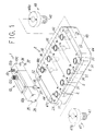
- FIGS. 1 to 3 show one embodiment of a manifold-type flow detector assembly according to this invention.
- This flow detector assembly is mainly composed of a plurality of flow detectors with a flow control valve 1 and a plurality of manifold blocks 2 on which the flow detectors are mounted.
- the flow detector 1 has a detection section 12a disposed in a fluid channel 11 penetrating the inside thereof, the fluid channel 11 is opened at the respective ends of the detector into an input and an output openings 13 and 14, and a flow control valve 15 is disposed in the fluid channel.
- the illustrated flow sensor 12 is of a type in which the detection section 12a detects the heat of a fluid flowing through the fluid channel 11, but a vortex type fluid sensor may be used.
- the flow detector 1 is composed of a flow detector body 10a comprising the fluid channel 11 penetrating the inside of the body and the flow sensor 12; an input block 10b mounted on the input side of the fluid channel 11 in the flow detector body 10a; and an output block 10c mounted on the output side of the fluid channel 11.
- the input and output blocks 10b and 10c have an input and an output channels 17 and 18, respectively, in communication with the fluid channel 11, and the input and output openings 13 and 14 are opened at the ends of the channels 17 and 18.
- the input and output openings 13 and 14 are opened at the centers of mounting surfaces 20 and 21 formed on the input and output blocks 10b and 10c in such a way as to be parallel to the axis of the fluid channel 11.
- the flow control valve 15 is disposed in the output channel 18 in the output block 10c.
- the flow sensor 12 comprises the detection section 12a disposed in the fluid channel 11 and is wired and connected via a printed circuit board 12b to an electric connector 12c which is in turn connected to a flow measuring apparatus.
- the flow control valve 15 for regulating the flow of fluid is shown as a restrictor, including a needle 15b the tip of which is opposed to a valve seat 15a of the output channel 18, which is screwed and inserted into the output block 10c via a seal member 15c, and which can be fixed using a lock nut 15d, another structure may be used instead.
- the flow control valve 15 is provided in the output block 10c, it may be provided in the input block 10b or in both input and output blocks 10b and 10c.
- filters 23a and 23b are locked at the input-side end of the fluid channel 11 in the flow detector body 10a using presser rings 24a and 24b, and a seal member 25a is disposed around the filters.
- a filter 23c is locked at the output-side end of the fluid channel 11 using a presser ring 24c, and a seal member 25c is disposed around the filter. Consequently, the fluid channel 11 in the flow detector body 10a and the input and output channels 17 and 18 in the input and output blocks 10b and 10c are joined together via the seal members 25a and 25c.
- the flow detector body 10a and each of the input and output blocks 10b and 10c are connected together at peripheral positions of the input and output blocks 10b and 10c separate from the channels, using screws 26.
- the connection means for connecting the flow detector body 10a and each of the input and output blocks 10b and 10c is not limited to the screw 26; instead, an arbitrary means can be used to connect them together at positions separate from the fluid channel 11.
- the fluid channel 11 has an almost uniform and linear cross section.
- the channel formed at the junction of each of the input and output blocks 10b and 10c with the flow detector body 10a has an almost uniform and linear cross section relative to the fluid channel 11.
- the input and output channels 17 and 18 in the input and output blocks 10a and 10b must be bent perpendicularly in the input and output blocks 10b and 10c so as to be mounted on the manifold block 2 at the mounting surfaces 20 and 21, which keep the flow detector 1 parallel to the axis of the fluid channel 11.
- the internal input channel 17 is smoothly bent to open the end of the internal input channel 17 in the mounting surface 20, while in the output block 10c in which the flow control valve 15 is mounted, the output side of the flow control valve 15 is opened in the mounting surface 21 without any need to complicate the internal channels.
- the manifold blocks 2 and 2A, on which the flow detector 1 is mounted at the mounting surfaces 20 and 21, have input and output passages 31 and 32 corresponding to the input and output openings 13 and 14 which in turn open into the mounting surfaces 20 and 21. Then, the input and output openings 13 and 14 in the flow detector 1 can be joined with the input and output passages 31 and 32 via seal members 33 and 34 to connect the flow detector and each of the input and output blocks together at the input and output passages 31 and 32 in the input and output blocks 10b and 10c and at mounting seats 35 and 36 at positions separate from the input and output openings 13 and 14, using screws 37. This connection enables the mounting and piping of the flow detector 1 to be simultaneously completed.
- connection means for connecting the flow detector 1 and the manifold blocks 2 and 2A together is not limited to the screw 37; an arbitrary means for fixedly connecting them together can be used as well.
- the input passage 31 is in communication with an input passageway, referred to hereinafter as the input common passage, and the output passage 32 is individually opened into an output port 42.
- a plurality of manifold blocks 2 and 2A are connected and fixed together using connection bolts 45 that penetrate end plates 44, as shown in FIG. 1.
- the manifold blocks are connected and fixed together in such a way that the input common passages 39 are mutually in communication, and the input common passages 39 are allowed to communicate with common input ports 41 provided in some of the manifold blocks 2A.
- the input port 41 is used for communication with a common fluid source, and the outport port 42 is used to output a fluid, the flow of which has been individually detected and measured by the flow detector 1 mounted on the manifold block.
- a joint member 47 having the input port 41 and a joint member 48 having the output port 42 have flange sections 47a and 48a, respectively, that are attached via seal members 47b and 48b to the periphery of the openings of the input common passages 39 in some of the manifold blocks 2A and the openings of the output passages 32 in the manifold blocks 2 and 2A.
- the joint members are fixed and connected using screws 47c and 48c that are screwed into the flange sections 47a and 48a from above the manifold block 2, or by some other connection means. Only one manifold block 2A including the joint member 47 must be included in a large number of manifold blocks connected together, but a plurality of manifold blocks 2A may be provided.
- the input port 41 in the manifold block 2A is connected to a fluid supply source, and the output port 42 in each manifold block is allowed to communicate with a plurality of loads to which a fluid is individually supplied.
- the flow of fluid supplied from the input port 41 through the input common passage 39 is detected by the detection section 12a of the flow sensor 12 in each flow detector 1, and the flow control valve 15 provided in the output block 10c regulates the flow to allow the fluid to be output from each output port 42 to the load.
- each flow detector 1 can set an arbitrary flow depending on each load.
- the input and output blocks 10b and 10c are mounted on and integrated with the input and output sides of the flow detector body 10a with the detection section 12a of the flow sensor 12 disposed in the fluid channel 11, and the flow control valve 15 is provided in the output block 10c. Consequently, the flow detector 1 can be configured to be small, and this integrated flow detector 1 can executed both flow measurement and regulation.
- the mounting surfaces 20 and 21 into which the input and output openings 13 and 14 in the input and output blocks 10b and 10c are opened are joined with and fixed to the manifold block 2.
- a plurality of manifold blocks 2 are connected and fixed together by allowing the input common passages 39 provided therein to communicate mutually, and the input common passages 39 are then allowed to communicate with the common input port 41.
- This configuration enables a large number of flow detectors 1 to be mounted easily without requiring a large space, and to be installed and removed easily for replacement, and also uses the common input port 41 to reduce the number of pipe joints required, thereby simplifying the piping operation while reducing piping configuration time.
- the flow detector body and each of the input and output blocks are connected together at positions separate from the channels using the screws 26 and 37.
- This configuration prevents any fine powder resulting from the installation or removal of screws from remaining in the channels during assembly of the flow detector 1 or manifold block 2 or during replacement of these parts.
- the flange sections 47a and 48a are provided in the joint members 47 and 48 having the input and output ports 41 and 42, respectively, and are attached to the periphery of the openings of the input common passage 39 and output passage 32 in the manifold blocks 2 and 2A via the seal members 47b and 48b.
- joint members of various shapes and structures can be used to deal with structural considerations relating to the mounting section of any machine or facility onto which this manifold-type flow detector assembly is mounted, thereby increasing this assembly's range of application.
- the flow detector assembly according to this invention can provide a flow detector assembly that functions as a flow sensor effectively suited for widespread use in clean environments such as a semiconductor fabrication apparatus, wherein a flow control valve can be assembled with the detector beforehand to allow the integrated apparatus to execute flow measurement and regulation, and wherein such detectors can be arranged and installed using manifold blocks, thereby enabling a plurality of flow detectors to be mounted simply on various equipment without any need for a large space.
Landscapes
- Engineering & Computer Science (AREA)
- Physics & Mathematics (AREA)
- Fluid Mechanics (AREA)
- Mechanical Engineering (AREA)
- General Engineering & Computer Science (AREA)
- General Physics & Mathematics (AREA)
- Valve Housings (AREA)
- Measuring Volume Flow (AREA)
Applications Claiming Priority (2)
| Application Number | Priority Date | Filing Date | Title |
|---|---|---|---|
| JP36203197A JP4042191B2 (ja) | 1997-12-11 | 1997-12-11 | マニホールド形流量検出器組立体 |
| JP36203197 | 1997-12-11 |
Publications (2)
| Publication Number | Publication Date |
|---|---|
| EP0922941A1 true EP0922941A1 (fr) | 1999-06-16 |
| EP0922941B1 EP0922941B1 (fr) | 2006-02-01 |
Family
ID=18475678
Family Applications (1)
| Application Number | Title | Priority Date | Filing Date |
|---|---|---|---|
| EP98309788A Expired - Lifetime EP0922941B1 (fr) | 1997-12-11 | 1998-11-30 | Distributeur avec capteurs de débit |
Country Status (7)
| Country | Link |
|---|---|
| US (1) | US6227248B1 (fr) |
| EP (1) | EP0922941B1 (fr) |
| JP (1) | JP4042191B2 (fr) |
| KR (1) | KR100302409B1 (fr) |
| CN (1) | CN1105294C (fr) |
| DE (1) | DE69833360T2 (fr) |
| TW (1) | TW367041U (fr) |
Cited By (3)
| Publication number | Priority date | Publication date | Assignee | Title |
|---|---|---|---|---|
| WO2001031313A1 (fr) * | 1999-10-18 | 2001-05-03 | Siemens Plc | Appareil pour mesurer la qualite de l'eau |
| EP1380845A1 (fr) * | 2002-07-13 | 2004-01-14 | Fluid Automation Systems S.A. | Détecteur de courant de gaz ou de liquide pour vannes |
| EP1757854A1 (fr) * | 2005-08-24 | 2007-02-28 | Toflo Corporation | Assemblage de tuyaux avec des capteurs d'écoulement intégrés |
Families Citing this family (10)
| Publication number | Priority date | Publication date | Assignee | Title |
|---|---|---|---|---|
| US20060071985A1 (en) * | 2004-10-06 | 2006-04-06 | Therien Patrick J | Fluid sensing apparatus for an ink supply system |
| US7575616B2 (en) * | 2006-02-10 | 2009-08-18 | Entegris, Inc. | Low-profile surface mount filter |
| JP4942613B2 (ja) * | 2007-10-30 | 2012-05-30 | 日本空圧システム株式会社 | 位置確認装置 |
| JP2011229693A (ja) * | 2010-04-28 | 2011-11-17 | Maezawa Ind Inc | 圧力検出機能を有する弁装置 |
| TWD164124S (zh) * | 2013-10-03 | 2014-11-11 | Smc股份有限公司 | 殘壓排氣閥間隔件之部分 |
| US20180080282A1 (en) * | 2015-04-01 | 2018-03-22 | Sandvik Intellectual Property Ab | Control unit for mining machine |
| CN105757385A (zh) * | 2016-05-05 | 2016-07-13 | 谢博 | 一种石油管道调控式计量分流器 |
| JP6665982B2 (ja) * | 2016-07-25 | 2020-03-13 | Smc株式会社 | マニホールド装置 |
| KR101985207B1 (ko) * | 2017-09-14 | 2019-06-04 | 주식회사아이센랩 | 매니폴드 일체형 밸브모듈 및 이를 구비한 가스성분 분석장치 |
| GB2640835B (en) * | 2024-04-29 | 2026-04-22 | Octopus Energy Heating Ltd | Methods and systems and apparatus to support reduced energy and water usage |
Citations (3)
| Publication number | Priority date | Publication date | Assignee | Title |
|---|---|---|---|---|
| US3785389A (en) * | 1971-08-09 | 1974-01-15 | Process Systems | Fluid flow control system |
| US4399836A (en) * | 1981-04-14 | 1983-08-23 | Marotta Scientific Controls, Inc. | Self-contained closed-loop electrically operated valve |
| WO1995007427A1 (fr) * | 1993-09-10 | 1995-03-16 | Deman Heiko T | Appareil et procede de reglage du debit des tetes d'arrosage |
Family Cites Families (5)
| Publication number | Priority date | Publication date | Assignee | Title |
|---|---|---|---|---|
| US4945344A (en) * | 1986-11-24 | 1990-07-31 | Farrell Jonathon E | Fluid flow sensor having light reflective slider |
| US5299447A (en) * | 1992-07-13 | 1994-04-05 | Ford Motor Company | Air flow manifold system for providing two different mass air flow rates to a mass air flow sensor production calibration station |
| JPH0932941A (ja) * | 1995-07-21 | 1997-02-07 | Smc Corp | 切換弁連設体 |
| KR100232112B1 (ko) * | 1996-01-05 | 1999-12-01 | 아마노 시게루 | 가스공급유닛 |
| JP4042190B2 (ja) * | 1997-12-11 | 2008-02-06 | Smc株式会社 | 流量調節弁付き流量検出器 |
-
1997
- 1997-12-11 JP JP36203197A patent/JP4042191B2/ja not_active Expired - Fee Related
-
1998
- 1998-11-18 TW TW087219124U patent/TW367041U/zh unknown
- 1998-11-19 US US09/195,684 patent/US6227248B1/en not_active Expired - Lifetime
- 1998-11-30 EP EP98309788A patent/EP0922941B1/fr not_active Expired - Lifetime
- 1998-11-30 DE DE69833360T patent/DE69833360T2/de not_active Expired - Lifetime
- 1998-12-11 KR KR1019980054551A patent/KR100302409B1/ko not_active Expired - Lifetime
- 1998-12-11 CN CN98117079A patent/CN1105294C/zh not_active Expired - Lifetime
Patent Citations (3)
| Publication number | Priority date | Publication date | Assignee | Title |
|---|---|---|---|---|
| US3785389A (en) * | 1971-08-09 | 1974-01-15 | Process Systems | Fluid flow control system |
| US4399836A (en) * | 1981-04-14 | 1983-08-23 | Marotta Scientific Controls, Inc. | Self-contained closed-loop electrically operated valve |
| WO1995007427A1 (fr) * | 1993-09-10 | 1995-03-16 | Deman Heiko T | Appareil et procede de reglage du debit des tetes d'arrosage |
Cited By (4)
| Publication number | Priority date | Publication date | Assignee | Title |
|---|---|---|---|---|
| WO2001031313A1 (fr) * | 1999-10-18 | 2001-05-03 | Siemens Plc | Appareil pour mesurer la qualite de l'eau |
| EP1380845A1 (fr) * | 2002-07-13 | 2004-01-14 | Fluid Automation Systems S.A. | Détecteur de courant de gaz ou de liquide pour vannes |
| EP1757854A1 (fr) * | 2005-08-24 | 2007-02-28 | Toflo Corporation | Assemblage de tuyaux avec des capteurs d'écoulement intégrés |
| US7225685B2 (en) | 2005-08-24 | 2007-06-05 | Toflo Corporation | Pipe assembly unit with built-in flow sensors |
Also Published As
| Publication number | Publication date |
|---|---|
| EP0922941B1 (fr) | 2006-02-01 |
| CN1226677A (zh) | 1999-08-25 |
| CN1105294C (zh) | 2003-04-09 |
| JP4042191B2 (ja) | 2008-02-06 |
| US6227248B1 (en) | 2001-05-08 |
| DE69833360D1 (de) | 2006-04-13 |
| JPH11173884A (ja) | 1999-07-02 |
| TW367041U (en) | 1999-08-11 |
| KR100302409B1 (ko) | 2002-02-28 |
| KR19990063010A (ko) | 1999-07-26 |
| DE69833360T2 (de) | 2006-10-26 |
Similar Documents
| Publication | Publication Date | Title |
|---|---|---|
| EP0922941A1 (fr) | Système de capteurs de débit du type distributeur | |
| US6076551A (en) | Flow detector with flow control valve | |
| US5988203A (en) | Two-piece manifold | |
| US8307854B1 (en) | Fluid delivery substrates for building removable standard fluid delivery sticks | |
| KR100232112B1 (ko) | 가스공급유닛 | |
| US20020023502A1 (en) | Manifold for use with a pressure transmitter | |
| EP1944583B1 (fr) | Débitmètre à pression différentielle | |
| EP0295845B1 (fr) | Oscillateur pour liquides | |
| JP4111786B2 (ja) | 表面実装モジュール流体フローシステム | |
| EP1015861B1 (fr) | Collecteur en deux pieces | |
| US5762100A (en) | Head for coplanar meter body transmitter | |
| US5567875A (en) | Modular gas meter assembly and associated manifold | |
| US20240426410A1 (en) | I-bridge | |
| US6609730B1 (en) | Stabilized mounting assembly with integral block module and manifold/transmitter module | |
| EP0604486B1 (fr) | Connexion interchangeable resistant aux erreurs d'installation | |
| US5083586A (en) | Mounting arrangement for connecting a fluid pressure valve to a pipe bracket by a hollow adapter member | |
| US4611836A (en) | Tubular connecting device | |
| GB2029564A (en) | Improvements in or relating to gas burner control assemblies. | |
| TW202310248A (zh) | 模組化配件組件以及包含該組件的系統 | |
| TW202530905A (zh) | 質量流量控制系統 | |
| SE455224B (sv) | Blandare med gengforbundna trycknipplar for tilloppsledningarna |
Legal Events
| Date | Code | Title | Description |
|---|---|---|---|
| PUAI | Public reference made under article 153(3) epc to a published international application that has entered the european phase |
Free format text: ORIGINAL CODE: 0009012 |
|
| 17P | Request for examination filed |
Effective date: 19981230 |
|
| AK | Designated contracting states |
Kind code of ref document: A1 Designated state(s): DE FR GB IT |
|
| AX | Request for extension of the european patent |
Free format text: AL;LT;LV;MK;RO;SI |
|
| AKX | Designation fees paid |
Free format text: DE FR GB IT |
|
| 17Q | First examination report despatched |
Effective date: 20030818 |
|
| GRAP | Despatch of communication of intention to grant a patent |
Free format text: ORIGINAL CODE: EPIDOSNIGR1 |
|
| GRAS | Grant fee paid |
Free format text: ORIGINAL CODE: EPIDOSNIGR3 |
|
| GRAA | (expected) grant |
Free format text: ORIGINAL CODE: 0009210 |
|
| AK | Designated contracting states |
Kind code of ref document: B1 Designated state(s): DE FR GB IT |
|
| PG25 | Lapsed in a contracting state [announced via postgrant information from national office to epo] |
Ref country code: IT Free format text: LAPSE BECAUSE OF FAILURE TO SUBMIT A TRANSLATION OF THE DESCRIPTION OR TO PAY THE FEE WITHIN THE PRESCRIBED TIME-LIMIT;WARNING: LAPSES OF ITALIAN PATENTS WITH EFFECTIVE DATE BEFORE 2007 MAY HAVE OCCURRED AT ANY TIME BEFORE 2007. THE CORRECT EFFECTIVE DATE MAY BE DIFFERENT FROM THE ONE RECORDED. Effective date: 20060201 |
|
| REG | Reference to a national code |
Ref country code: GB Ref legal event code: FG4D |
|
| REF | Corresponds to: |
Ref document number: 69833360 Country of ref document: DE Date of ref document: 20060413 Kind code of ref document: P |
|
| PLBE | No opposition filed within time limit |
Free format text: ORIGINAL CODE: 0009261 |
|
| STAA | Information on the status of an ep patent application or granted ep patent |
Free format text: STATUS: NO OPPOSITION FILED WITHIN TIME LIMIT |
|
| 26N | No opposition filed |
Effective date: 20061103 |
|
| EN | Fr: translation not filed | ||
| GBPC | Gb: european patent ceased through non-payment of renewal fee |
Effective date: 20061130 |
|
| PG25 | Lapsed in a contracting state [announced via postgrant information from national office to epo] |
Ref country code: GB Free format text: LAPSE BECAUSE OF NON-PAYMENT OF DUE FEES Effective date: 20061130 |
|
| PG25 | Lapsed in a contracting state [announced via postgrant information from national office to epo] |
Ref country code: FR Free format text: LAPSE BECAUSE OF FAILURE TO SUBMIT A TRANSLATION OF THE DESCRIPTION OR TO PAY THE FEE WITHIN THE PRESCRIBED TIME-LIMIT Effective date: 20070323 |
|
| PG25 | Lapsed in a contracting state [announced via postgrant information from national office to epo] |
Ref country code: FR Free format text: LAPSE BECAUSE OF FAILURE TO SUBMIT A TRANSLATION OF THE DESCRIPTION OR TO PAY THE FEE WITHIN THE PRESCRIBED TIME-LIMIT Effective date: 20060201 |
|
| PGFP | Annual fee paid to national office [announced via postgrant information from national office to epo] |
Ref country code: DE Payment date: 20171121 Year of fee payment: 20 |
|
| REG | Reference to a national code |
Ref country code: DE Ref legal event code: R071 Ref document number: 69833360 Country of ref document: DE |