EP0923007A2 - Entwicklerzufuhrverfahren für einen elektrographischen Drucker mit Flüssigentwicklung - Google Patents
Entwicklerzufuhrverfahren für einen elektrographischen Drucker mit Flüssigentwicklung Download PDFInfo
- Publication number
- EP0923007A2 EP0923007A2 EP98306000A EP98306000A EP0923007A2 EP 0923007 A2 EP0923007 A2 EP 0923007A2 EP 98306000 A EP98306000 A EP 98306000A EP 98306000 A EP98306000 A EP 98306000A EP 0923007 A2 EP0923007 A2 EP 0923007A2
- Authority
- EP
- European Patent Office
- Prior art keywords
- developer
- reservoir
- level
- concentration
- ink
- Prior art date
- Legal status (The legal status is an assumption and is not a legal conclusion. Google has not performed a legal analysis and makes no representation as to the accuracy of the status listed.)
- Granted
Links
Images


Classifications
-
- G—PHYSICS
- G03—PHOTOGRAPHY; CINEMATOGRAPHY; ANALOGOUS TECHNIQUES USING WAVES OTHER THAN OPTICAL WAVES; ELECTROGRAPHY; HOLOGRAPHY
- G03G—ELECTROGRAPHY; ELECTROPHOTOGRAPHY; MAGNETOGRAPHY
- G03G15/00—Apparatus for electrographic processes using a charge pattern
- G03G15/06—Apparatus for electrographic processes using a charge pattern for developing
-
- G—PHYSICS
- G03—PHOTOGRAPHY; CINEMATOGRAPHY; ANALOGOUS TECHNIQUES USING WAVES OTHER THAN OPTICAL WAVES; ELECTROGRAPHY; HOLOGRAPHY
- G03G—ELECTROGRAPHY; ELECTROPHOTOGRAPHY; MAGNETOGRAPHY
- G03G15/00—Apparatus for electrographic processes using a charge pattern
- G03G15/06—Apparatus for electrographic processes using a charge pattern for developing
- G03G15/10—Apparatus for electrographic processes using a charge pattern for developing using a liquid developer
- G03G15/104—Preparing, mixing, transporting or dispensing developer
- G03G15/105—Detection or control means for the toner concentration
Definitions
- the present invention relates to a wet electrographic printer, and more particularly, to a developer supply method of a wet electrographic printer, capable of controlling the concentration and level of the developer.
- a wet electrographic printer is an apparatus for developing an electrostatic latent image, formed on a photosensitive medium such as a photosensitive belt, with a developer of a predetermined color and transferring the developed image to then print a desired image on a substrate such as a paper sheet.
- the wet electrographic printer includes a developing unit for developing an image by supplying the developer to the photosensitive medium, and a developer supply apparatus for constantly supplying developer of a predetermined density to the developing unit.
- the developer is a mixture of a condensed ink, containing a powdery toner, with a liquid carrier, in which the toner is diluted to approximately 2 ⁇ 4 wt%.
- the concentration of the developer is defined by the wt% of toner.
- the developer supply apparatus includes an ink cartridge for storing the condensed ink, a carrier cartridge for storing the liquid carrier, and a reservoir for storing the developer obtained by mixing the condensed ink with the liquid carrier at a predetermined ratio. Also, agitators for preventing the toner from settling out of the solution may be installed in the ink cartridge and the reservoir.
- the amount of developer stored in the reservoir is reduced by the amount used to develop the electrostatic latent image of the photosensitive medium, so that the condensed ink and the liquid carrier must be supplied to the reservoir to maintain the developer at a constant concentration. Also, the level of developer stored in the reservoir must be maintained at a constant level.
- the consumption of toner and liquid carrier may vary with images to be printed. That is, more liquid carrier than toner is consumed to print a simple image or a small image, and more toner than liquid carrier is required to print a complicated image.
- the developer supply method cannot control both the concentration of the developer stored in the reservoir and the level thereof. That is, if a lot of the liquid carrier is supplied to maintain a predetermined concentration of the developer in the reservoir, the level of the developer changes and thus undesired operating conditions may develop. On the other hand, if the level of the developer is controlled, the concentration of the developer may not be maintained at a constant level.
- a developer supply method of a wet electrographic printer having a reservoir for supplying a developer obtained by mixing a liquid carrier with an ink to a developing unit, a carrier cartridge for supplying the liquid carrier to the reservoir, an ink cartridge for supplying the ink to the reservoir, and a process tank for receiving the processor from the reservoir, includes the steps of: supplying the liquid carrier and the ink to the reservoir to have an optimum concentration and a maximum level; determining whether the concentration of the developer in the reservoir is less than a minimum concentration, and the level of the developer is less than a minimum level; draining the developer of the reservoir to the process tank such that the level of the developer becomes the minimum level, if the concentration of the developer is less than the minimum concentration and the level is higher than the minimum level, in the determining step, supplying the liquid carrier and the ink to the reservoir such that the developer in the reservoir has the optimum concentration and the maximum level, and supplying the liquid carrier and ink to the reservoir such that the developer has the optimum concentration and the maximum level, and supplying the
- the method further includes the steps of determining whether the level of the developer in the process tank is higher than a predetermined recycle level, and supplying the predetermined recycle amount of the developer of the process tank to the reservoir, if the level of the developer in the process tank is higher than the recycle level in the determining step.
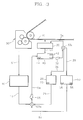
- liquid carrier is stored in a carrier cartridge 10
- condensed ink is stored in an ink cartridge 20.
- the carrier cartridge 10 and the ink cartridge 20 are replaceable.
- the carrier cartridge 10 and the ink cartridge 20 are connected to a first valve 53 such as a solenoid two-way valve through a carrier supply path 11 and an ink supply path 21 respectively.
- the first valve 53 selectively opens and closes the carrier supply path 11 and the ink supply path 21, so that ink and liquid carrier are supplied to a reservoir 40 through an ink/carrier supply path 54 by the driving force of a first pump 55.
- a level sensor 42 for sensing the level of the developer in the reservoir 40, and a concentration sensor 44 for sensing the concentration thereof, are installed in the reservoir 40.
- the reservoir 40 supplies the developer obtained by mixing the ink with the liquid carrier to a developing unit 30 through a developer supply path 34 by the driving force of a second pump 32.
- the developing unit 30 develops an electrostatic latent image formed on a photosensitive belt 70 using the developer supplied from the reservoir 40.
- a second valve 33 such as a solenoid two-way valve is installed in the developer supply path 34, and the second valve 33 selectively blocks the developer supply path 34 and a developer drain path 35, to direct the developer to the developer unit 30 and a process tank 50 through the developer supply path 34 and the developer drain path 35, respectively.
- Reference numeral 60 denotes a drying unit for recovering liquid carrier adhering to the electrostatic latent image of the photosensitive belt 70, where the collected liquid carrier returns to the carrier cartridge 10 along a collection pipe 61.
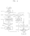
- the liquid carrier and ink are supplied to the reservoir 40 (step 210). That is, the first valve 53 selectively opens the ink supply path 21 and the carrier supply path 11 to supply ink and liquid carrier from the ink cartridge 20 and the carrier cartridge 10 to the reservoir 40 through the ink/carrier supply path 54.
- the supplied ink and liquid carrier are mixed to be useable for printing, and the concentration D x of the developer becomes an optimum concentration D opt between the minimum concentration D min and the maximum concentration D max and the level L x of the developer becomes a maximum level L max .
- the concentration and level of the developer are properly controlled according to printing conditions.
- the developer in the reservoir 40 is supplied to the developing unit 30 along the developer supply path 34 by the driving force of the second pump 32. At this time, the developer drain path 35 is closed by the second valve 33. Thus, the electrostatic latent image formed on the photosensitive belt 70 is developed using the supplied developer. At this time, excess developer supplied to the photosensitive belt 70 is eliminated by collection means such as a squeegee roller (not shown), to be collected in the reservoir 40 through the path 31.
- collection means such as a squeegee roller (not shown), to be collected in the reservoir 40 through the path 31.
- the concentration sensor 44 determines whether the concentration D x of the developer in the reservoir 40 has a minimum concentration D min (step 220) .
- the minimum concentration D min is determined by the criterion that print quality starts to deteriorate unacceptably.
- the concentration sensor 44 senses and measures the abnormal concentration of the developer to transmit the measured concentration to a controller (not shown).
- the controller stops the printing according to the signals, and operates the second valve 33 to block the developer supply path 34 and open the developer drain path 35.
- the developer in the reservoir is drained to the process tank 50 by the second pump 32. This ensures sufficient room in the reservoir 40 into which to supply new ink and liquid carrier.
- step 240 it is determined whether the level L x of the developer measured by the level sensor 42 installed in the reservoir 40 is less than a predetermined minimum level L min (step 240). If the level of the developer is higher than the minimum level L min , the sequence returns to the step 230.
- the minimum level L min is properly determined based on the capacity of the reservoir 40.
- the first valve 53 operates to supply liquid carrier and/or ink to the reservoir 40 such that the level L x of the developer reaches the maximum level L max (step 250). At this time, the amounts of the supplied liquid carrier and ink are controlled such that the final developer has the optimum concentration D opt and maximum level L max . Thus, the sequence proceeds to step 280.
- step 260 it is determined whether the level L x of the developer is less than the minimum level L min.
- step 260 If the level L x of the developer is less than the minimum level L min in step 260, the liquid carrier and/or ink is supplied to the reservoir 40 such that the developer in the reservoir 40 has the optimum concentration D opt and the maximum level L max (step 270), and if the level L x of the developer is higher than the minimum level L min , the sequence proceeds to step 280.
- the printing is performed under conditions in which the concentration and level of the developer in the reservoir 40 are normal (step 280).
- step 290 It is determined whether the printing is finished or not (step 290). If the printing is not finished, the sequence returns to step 220.
- the concentration and level of the developer are inappropriate, the developer in the reservoir 40 is partially drained to the process tank 50, to thereby ensure sufficient room for supplying new ink and liquid carrier.
- the concentration and level of the developer can be relatively easily controlled.
- the process tank 50 is connected to a third valve 53a such as a solenoid three-way valve by a recycle path 51.
- a third valve 53a such as a solenoid three-way valve
- the developer in the process tank 50 is supplied to the reservoir 40 by the recycle path 51 and the third valve 53a, to be reused.
- Steps 210 through 290 are the same as the above-described embodiment.
- step 410 If the level L x measured in step 260 is less than the minimum level L min , it is determined whether the level L p, x of the developer in the process tank 50 measured by a level sensor 58 is less than a predetermined recycle level L r (step 410).
- the level L p, x of the developer in the process tank 50 is less than the recycle level L r , it means that the developer stored in the process tank 50 is insufficient for the amount of supply to the reservoir 40.
- carrier and/or ink is supplied from the carrier cartridge 10 and the ink cartridge 20 to the reservoir 40 (step 270).
- the concentration D p, x of the developer in the process tank 50 is measured by a concentration sensor 56.
- the developer of the process tank 50 is supplied to the reservoir 40 together with liquid carrier and/or ink until the level L x of the final developer in the reservoir 40 reaches the maximum level L max .
- the supply ratio of the liquid carrier and ink is properly controlled according to the concentration D p, x of the developer in the process tank, so that the developer in the reservoir 40 has the optimum concentration D opt .
- step 280 the printing is performed in the same manner described in step 280.
- the developer used in the example embodiment is a solution obtained by mixing approximately 133ml of ink containing 9wt% of toner with approximately 267ml of liquid carrier, where the concentration of the final developer is approximately 3wt% (optimum concentration). Also, the maximum level L max of the reservoir 40 is approximately 400ml, and the minimum level L min thereof is 340ml.
- the "coverage" used in the example embodiment is defined as the ratio of the area of a printed image to that of a sheet of A4 paper.
- the concentration of the developer in the reservoir 40 becomes 2wt%, which is a minimum concentration D min (step 220 of Figure 2), and the level of the developer becomes approximately 345ml. Then, the controller temporarily stops the printing upon receiving a signal transmitted from the concentration sensor 44.
- step 230 5ml of the developer in the reservoir 40 is drained to the process tank 50 (step 230), so that the level of the reservoir 40 becomes a minimum level L min of 340ml (step 240). Then, 60ml of the ink in the ink cartridge 20 is supplied to the reservoir 40 (step 250). Thus, the concentration and level of the final developer in the reservoir 40 become 3wt% and 400ml, respectively. Subsequently, the printing is resumed.
- the concentration and level of developer in the reservoir 40 becomes 2wt%, which is the minimum concentration, and 390ml, respectively.
- the printing is stopped (step 220 of Figure 2), and then 50ml of the developer is drained from the reservoir 40 to the process tank 50 (steps 230 and 240).
- the concentration and level of the developer in the reservoir 40 become 3wt% and 400ml, respectively.
- the concentration and level of the developer in the reservoir 40 become 3.5wt% and 340ml, which is the minimum level L min .
- the level L x of the developer in the reservoir 40 measured by the level sensor 42 becomes the minimum level L min , so that the operation of the printer is stopped by the controller (step 260 of Figure 1).
- the concentration and level of the developer in the reservoir 40 become 2,45wt% and 340ml, which is a minimum level, so that the printing is temporarily stopped (step 260 of Figure 4).
- the process tank 50 still contains more than the recycle level L r , i.e., 30ml, of developer having concentration of 2wt% concentration, (step 410).
- step 270 If the developer in the process tank 50 is less than the recycle level L r , i.e., 30ml in step 410, 40.7ml of the ink in the ink cartridge and 19.3ml of the liquid carrier in the carrier cartridge 10 are supplied to the reservoir 40 (step 270).
- an additional process tank is provided, into which the developer in the reservoir is drained, to thereby easily control the concentration and level of the developer. Also, the developer in the process tank can be reused while maintaining the correct developer concentration.
- the developer supply method for one developing unit is disclosed.
- the above developer supply method may also be employed in an electrographic color printer having a plurality of developing units corresponding to colors of, for example, yellow, magenta, cyan and black.
Landscapes
- Physics & Mathematics (AREA)
- General Physics & Mathematics (AREA)
- Wet Developing In Electrophotography (AREA)
Applications Claiming Priority (2)
| Application Number | Priority Date | Filing Date | Title |
|---|---|---|---|
| KR1019970068323A KR100252101B1 (ko) | 1997-12-12 | 1997-12-12 | 습식 현상기의 현상액 공급방법 |
| KR9768323 | 1997-12-12 |
Publications (4)
| Publication Number | Publication Date |
|---|---|
| EP0923007A2 true EP0923007A2 (de) | 1999-06-16 |
| EP0923007A3 EP0923007A3 (de) | 2001-03-28 |
| EP0923007B1 EP0923007B1 (de) | 2004-03-17 |
| EP0923007B9 EP0923007B9 (de) | 2004-09-29 |
Family
ID=19527201
Family Applications (1)
| Application Number | Title | Priority Date | Filing Date |
|---|---|---|---|
| EP98306000A Expired - Lifetime EP0923007B9 (de) | 1997-12-12 | 1998-07-28 | Entwicklerzufuhrverfahren für einen elektrographischen Drucker mit Flüssigentwicklung |
Country Status (6)
| Country | Link |
|---|---|
| US (1) | US5926668A (de) |
| EP (1) | EP0923007B9 (de) |
| JP (1) | JP2904776B1 (de) |
| KR (1) | KR100252101B1 (de) |
| CN (1) | CN1112605C (de) |
| DE (1) | DE69822416T2 (de) |
Cited By (15)
| Publication number | Priority date | Publication date | Assignee | Title |
|---|---|---|---|---|
| EP0923008A3 (de) * | 1997-12-12 | 2001-03-21 | Samsung Electronics Co., Ltd. | Entwicklerzufuhrgerät für einen elektrographischen Drucker mit Flüssigentwicklung |
| EP0923006A3 (de) * | 1997-12-12 | 2001-04-04 | Samsung Electronics Co., Ltd. | Entwicklerzufuhrverfahren für einen elektrographischen Drucker mit Flüssigentwicklung |
| WO2018184648A1 (en) * | 2017-04-05 | 2018-10-11 | Hp Indigo B.V. | Detecting arrival of ink in a liquid ink printing system |
| CN113692354A (zh) * | 2019-03-31 | 2021-11-23 | 兰达公司 | 用于预防或最小化印刷过程中印刷缺陷的系统和方法 |
| US11655382B2 (en) | 2013-09-11 | 2023-05-23 | Landa Corporation Ltd. | Ink formulations and film constructions thereof |
| US11660857B2 (en) | 2015-03-20 | 2023-05-30 | Landa Corporation Ltd. | Indirect printing system |
| US11679615B2 (en) | 2017-12-07 | 2023-06-20 | Landa Corporation Ltd. | Digital printing process and method |
| US11697291B2 (en) | 2016-05-30 | 2023-07-11 | Landa Corporation Ltd. | Digital printing process |
| US11707943B2 (en) | 2017-12-06 | 2023-07-25 | Landa Corporation Ltd. | Method and apparatus for digital printing |
| US11713399B2 (en) | 2012-03-05 | 2023-08-01 | Landa Corporation Ltd. | Ink film constructions |
| US11724488B2 (en) | 2016-05-30 | 2023-08-15 | Landa Corporation Ltd. | Digital printing process and system |
| US11724487B2 (en) | 2012-03-05 | 2023-08-15 | Landa Corporation Ltd. | Apparatus and method for control or monitoring a printing system |
| US11787170B2 (en) | 2018-12-24 | 2023-10-17 | Landa Corporation Ltd. | Digital printing system |
| US11833847B2 (en) | 2018-06-26 | 2023-12-05 | Landa Corporation Ltd. | Intermediate transfer member for a digital printing system |
| US11884089B2 (en) | 2012-03-05 | 2024-01-30 | Landa Corporation Ltd. | Printing system |
Families Citing this family (21)
| Publication number | Priority date | Publication date | Assignee | Title |
|---|---|---|---|---|
| JP2000284447A (ja) * | 1999-03-30 | 2000-10-13 | Fuji Photo Film Co Ltd | 自動現像機の処理補充液検出装置 |
| JP2001201943A (ja) * | 2000-01-17 | 2001-07-27 | Nec Niigata Ltd | 静電式湿式電子写真方式印刷機の現像液調整装置 |
| JP2001265125A (ja) | 2000-03-16 | 2001-09-28 | Nec Niigata Ltd | 液体現像装置及びこれを使用する画像形成装置 |
| KR100385991B1 (ko) * | 2001-02-03 | 2003-06-02 | 삼성전자주식회사 | 습식 전자사진방식 인쇄기의 잉크전달시스템 및잉크전달방법 |
| JP2002304061A (ja) * | 2001-04-09 | 2002-10-18 | Toshiba Mach Co Ltd | 湿式電子写真印刷機の濃縮トナー補充装置および濃縮トナー補充方法 |
| WO2013132418A2 (en) | 2012-03-05 | 2013-09-12 | Landa Corporation Limited | Digital printing process |
| US11809100B2 (en) | 2012-03-05 | 2023-11-07 | Landa Corporation Ltd. | Intermediate transfer members for use with indirect printing systems and protonatable intermediate transfer members for use with indirect printing systems |
| US11104123B2 (en) | 2012-03-05 | 2021-08-31 | Landa Corporation Ltd. | Digital printing system |
| CN109177531B (zh) | 2012-03-15 | 2020-11-27 | 兰达公司 | 打印系统的环形柔性皮带 |
| GB2537813A (en) | 2015-04-14 | 2016-11-02 | Landa Corp Ltd | Apparatus for threading an intermediate transfer member of a printing system |
| GB201609463D0 (en) | 2016-05-30 | 2016-07-13 | Landa Labs 2012 Ltd | Method of manufacturing a multi-layer article |
| DE112017002714T5 (de) | 2016-05-30 | 2019-02-28 | Landa Corporation Ltd. | Digitales Druckverfahren |
| JP7225230B2 (ja) | 2017-11-19 | 2023-02-20 | ランダ コーポレイション リミテッド | デジタル印刷システム |
| WO2019102297A1 (en) | 2017-11-27 | 2019-05-31 | Landa Corporation Ltd. | Digital printing system |
| US10994528B1 (en) | 2018-08-02 | 2021-05-04 | Landa Corporation Ltd. | Digital printing system with flexible intermediate transfer member |
| US12001902B2 (en) | 2018-08-13 | 2024-06-04 | Landa Corporation Ltd. | Correcting distortions in digital printing by implanting dummy pixels in a digital image |
| JP7246496B2 (ja) | 2018-10-08 | 2023-03-27 | ランダ コーポレイション リミテッド | 印刷システムおよび方法に関する摩擦低減手段 |
| CN114746813A (zh) | 2019-11-25 | 2022-07-12 | 兰达公司 | 在数字印刷中使用红外辐射来干燥油墨 |
| US11321028B2 (en) | 2019-12-11 | 2022-05-03 | Landa Corporation Ltd. | Correcting registration errors in digital printing |
| EP4081866A4 (de) | 2019-12-29 | 2024-01-03 | Landa Corporation Ltd. | Druckverfahren und -system |
| EP4264377A4 (de) | 2021-02-02 | 2024-11-13 | Landa Corporation Ltd. | Abschwächung von verzerrungen in druckbildern |
Family Cites Families (6)
| Publication number | Priority date | Publication date | Assignee | Title |
|---|---|---|---|---|
| US3789794A (en) * | 1971-12-27 | 1974-02-05 | Savin Business Machines Corp | Apparatus for developing electrostatic images |
| JPS5950472A (ja) * | 1982-09-16 | 1984-03-23 | Ricoh Co Ltd | 湿式現像装置 |
| GB2177626B (en) * | 1985-07-10 | 1989-12-28 | Ricoh Kk | Developing device for electrophotographic color copier |
| US5003352A (en) * | 1989-10-24 | 1991-03-26 | Am International, Inc. | Liquid toner supply system and method |
| JPH09311557A (ja) * | 1996-05-16 | 1997-12-02 | Ricoh Co Ltd | 湿式現像装置 |
| KR100287142B1 (ko) * | 1997-12-12 | 2001-04-16 | 윤종용 | 습식현상기용현상액공급장치의현상액공급방법 |
-
1997
- 1997-12-12 KR KR1019970068323A patent/KR100252101B1/ko not_active Expired - Fee Related
-
1998
- 1998-06-18 JP JP10171158A patent/JP2904776B1/ja not_active Expired - Fee Related
- 1998-07-13 CN CN98116013A patent/CN1112605C/zh not_active Expired - Fee Related
- 1998-07-28 EP EP98306000A patent/EP0923007B9/de not_active Expired - Lifetime
- 1998-07-28 DE DE1998622416 patent/DE69822416T2/de not_active Expired - Fee Related
- 1998-07-30 US US09/124,643 patent/US5926668A/en not_active Expired - Lifetime
Cited By (20)
| Publication number | Priority date | Publication date | Assignee | Title |
|---|---|---|---|---|
| EP0923006A3 (de) * | 1997-12-12 | 2001-04-04 | Samsung Electronics Co., Ltd. | Entwicklerzufuhrverfahren für einen elektrographischen Drucker mit Flüssigentwicklung |
| EP0923008A3 (de) * | 1997-12-12 | 2001-03-21 | Samsung Electronics Co., Ltd. | Entwicklerzufuhrgerät für einen elektrographischen Drucker mit Flüssigentwicklung |
| US11884089B2 (en) | 2012-03-05 | 2024-01-30 | Landa Corporation Ltd. | Printing system |
| US11724487B2 (en) | 2012-03-05 | 2023-08-15 | Landa Corporation Ltd. | Apparatus and method for control or monitoring a printing system |
| US11713399B2 (en) | 2012-03-05 | 2023-08-01 | Landa Corporation Ltd. | Ink film constructions |
| US11655382B2 (en) | 2013-09-11 | 2023-05-23 | Landa Corporation Ltd. | Ink formulations and film constructions thereof |
| US11660857B2 (en) | 2015-03-20 | 2023-05-30 | Landa Corporation Ltd. | Indirect printing system |
| US11697291B2 (en) | 2016-05-30 | 2023-07-11 | Landa Corporation Ltd. | Digital printing process |
| US12384170B2 (en) | 2016-05-30 | 2025-08-12 | Landa Corporation Ltd. | Digital printing process |
| US11724488B2 (en) | 2016-05-30 | 2023-08-15 | Landa Corporation Ltd. | Digital printing process and system |
| US10875292B2 (en) | 2017-04-05 | 2020-12-29 | Hp Indigo B.V. | Detecting arrival of ink in a liquid ink printing system |
| US20200079075A1 (en) * | 2017-04-05 | 2020-03-12 | Hp Indigo B.V. | Detecting arrival of ink in a liquid ink printing system |
| WO2018184648A1 (en) * | 2017-04-05 | 2018-10-11 | Hp Indigo B.V. | Detecting arrival of ink in a liquid ink printing system |
| US11707943B2 (en) | 2017-12-06 | 2023-07-25 | Landa Corporation Ltd. | Method and apparatus for digital printing |
| US11679615B2 (en) | 2017-12-07 | 2023-06-20 | Landa Corporation Ltd. | Digital printing process and method |
| US11833847B2 (en) | 2018-06-26 | 2023-12-05 | Landa Corporation Ltd. | Intermediate transfer member for a digital printing system |
| US11787170B2 (en) | 2018-12-24 | 2023-10-17 | Landa Corporation Ltd. | Digital printing system |
| CN113692354B (zh) * | 2019-03-31 | 2024-03-26 | 兰达公司 | 用于预防或最小化印刷过程中印刷缺陷的系统和方法 |
| US12358277B2 (en) | 2019-03-31 | 2025-07-15 | Landa Corporation Ltd. | Systems and methods for preventing or minimizing printing defects in printing processes |
| CN113692354A (zh) * | 2019-03-31 | 2021-11-23 | 兰达公司 | 用于预防或最小化印刷过程中印刷缺陷的系统和方法 |
Also Published As
| Publication number | Publication date |
|---|---|
| EP0923007A3 (de) | 2001-03-28 |
| DE69822416D1 (de) | 2004-04-22 |
| EP0923007B1 (de) | 2004-03-17 |
| US5926668A (en) | 1999-07-20 |
| EP0923007B9 (de) | 2004-09-29 |
| CN1219690A (zh) | 1999-06-16 |
| KR100252101B1 (ko) | 2000-04-15 |
| KR19990049384A (ko) | 1999-07-05 |
| JPH11184258A (ja) | 1999-07-09 |
| CN1112605C (zh) | 2003-06-25 |
| DE69822416T2 (de) | 2005-01-13 |
| JP2904776B1 (ja) | 1999-06-14 |
Similar Documents
| Publication | Publication Date | Title |
|---|---|---|
| EP0923007B1 (de) | Entwicklerzufuhrverfahren für einen elektrographischen Drucker mit Flüssigentwicklung | |
| CN102004414B (zh) | 图像形成设备 | |
| EP0923006B1 (de) | Entwicklerzufuhrverfahren für einen elektrographischen Drucker mit Flüssigentwicklung | |
| EP0923005B1 (de) | Entwicklerzufuhrvorrichtung für einen elektrographischen Drucker mit Flüssigentwicklung | |
| US6466749B1 (en) | Adjustable developer ratio forming method and apparatus | |
| JP2003076079A (ja) | 画像形成装置 | |
| EP0923008A2 (de) | Entwicklerzufuhrgerät für einen elektrographischen Drucker mit Flüssigentwicklung | |
| JP2003167442A (ja) | 高粘性の液体現像液を用いた電子写真装置のトナーリサイクル制御方式 | |
| KR100385991B1 (ko) | 습식 전자사진방식 인쇄기의 잉크전달시스템 및잉크전달방법 | |
| US5963758A (en) | System and method for maintaining color density in liquid toners for an electrographic printer | |
| EP1403739A2 (de) | Bilderzeugungsgerät und Verfahren unter Verwendung eines Flüssigentwicklers | |
| US20080310870A1 (en) | Method for Developing Potential Images Which are Produced on an Intermediate Image Carrier of Images Which are to be Printed Having Selectable Customer-Specific Colors in an Electrographic Printing or Copying Device | |
| KR100374468B1 (ko) | 잉크 농도 조정 기구 및 잉크 농도 조정 기구를 이용한전자 사진 장치 | |
| US7437106B2 (en) | Device and method for the replacement of expired developer | |
| US7257354B2 (en) | Device and method for the replacement of out-of-date developer | |
| KR20010017971A (ko) | 습식 전자사진방식 칼라 인쇄기의 현상액 공급장치 | |
| KR100327205B1 (ko) | 습식전자사진방식프린터의현상액순환시스템및이를사용한현상액농도조절방법 | |
| JP2000047446A (ja) | カラー画像形成装置 |
Legal Events
| Date | Code | Title | Description |
|---|---|---|---|
| PUAI | Public reference made under article 153(3) epc to a published international application that has entered the european phase |
Free format text: ORIGINAL CODE: 0009012 |
|
| 17P | Request for examination filed |
Effective date: 19980813 |
|
| AK | Designated contracting states |
Kind code of ref document: A2 Designated state(s): DE FR GB |
|
| AX | Request for extension of the european patent |
Free format text: AL;LT;LV;MK;RO;SI |
|
| PUAL | Search report despatched |
Free format text: ORIGINAL CODE: 0009013 |
|
| AK | Designated contracting states |
Kind code of ref document: A3 Designated state(s): AT BE CH CY DE DK ES FI FR GB GR IE IT LI LU MC NL PT SE |
|
| AX | Request for extension of the european patent |
Free format text: AL;LT;LV;MK;RO;SI |
|
| AKX | Designation fees paid |
Free format text: DE FR GB |
|
| 17Q | First examination report despatched |
Effective date: 20030416 |
|
| GRAP | Despatch of communication of intention to grant a patent |
Free format text: ORIGINAL CODE: EPIDOSNIGR1 |
|
| GRAS | Grant fee paid |
Free format text: ORIGINAL CODE: EPIDOSNIGR3 |
|
| GRAA | (expected) grant |
Free format text: ORIGINAL CODE: 0009210 |
|
| AK | Designated contracting states |
Kind code of ref document: B1 Designated state(s): DE FR GB |
|
| REG | Reference to a national code |
Ref country code: GB Ref legal event code: FG4D |
|
| REF | Corresponds to: |
Ref document number: 69822416 Country of ref document: DE Date of ref document: 20040422 Kind code of ref document: P |
|
| ET | Fr: translation filed | ||
| PLBE | No opposition filed within time limit |
Free format text: ORIGINAL CODE: 0009261 |
|
| STAA | Information on the status of an ep patent application or granted ep patent |
Free format text: STATUS: NO OPPOSITION FILED WITHIN TIME LIMIT |
|
| 26N | No opposition filed |
Effective date: 20041220 |
|
| PGFP | Annual fee paid to national office [announced via postgrant information from national office to epo] |
Ref country code: DE Payment date: 20080807 Year of fee payment: 11 |
|
| PGFP | Annual fee paid to national office [announced via postgrant information from national office to epo] |
Ref country code: FR Payment date: 20080718 Year of fee payment: 11 |
|
| PGFP | Annual fee paid to national office [announced via postgrant information from national office to epo] |
Ref country code: GB Payment date: 20080806 Year of fee payment: 11 |
|
| GBPC | Gb: european patent ceased through non-payment of renewal fee |
Effective date: 20090728 |
|
| REG | Reference to a national code |
Ref country code: FR Ref legal event code: ST Effective date: 20100331 |
|
| PG25 | Lapsed in a contracting state [announced via postgrant information from national office to epo] |
Ref country code: FR Free format text: LAPSE BECAUSE OF NON-PAYMENT OF DUE FEES Effective date: 20090731 |
|
| PG25 | Lapsed in a contracting state [announced via postgrant information from national office to epo] |
Ref country code: GB Free format text: LAPSE BECAUSE OF NON-PAYMENT OF DUE FEES Effective date: 20090728 |
|
| PG25 | Lapsed in a contracting state [announced via postgrant information from national office to epo] |
Ref country code: DE Free format text: LAPSE BECAUSE OF NON-PAYMENT OF DUE FEES Effective date: 20100202 |
|
| REG | Reference to a national code |
Ref country code: GB Ref legal event code: 732E Free format text: REGISTERED BETWEEN 20170406 AND 20170412 |
|
| REG | Reference to a national code |
Ref country code: FR Ref legal event code: TP Owner name: S-PRINTING SOLUTION CO., LTD., KR Effective date: 20170912 |