EP0923091B1 - Actionneur électromagnétique à ensemble de noyaux composites - Google Patents
Actionneur électromagnétique à ensemble de noyaux composites Download PDFInfo
- Publication number
- EP0923091B1 EP0923091B1 EP98123242A EP98123242A EP0923091B1 EP 0923091 B1 EP0923091 B1 EP 0923091B1 EP 98123242 A EP98123242 A EP 98123242A EP 98123242 A EP98123242 A EP 98123242A EP 0923091 B1 EP0923091 B1 EP 0923091B1
- Authority
- EP
- European Patent Office
- Prior art keywords
- core member
- laminations
- core
- stacking axis
- core assembly
- Prior art date
- Legal status (The legal status is an assumption and is not a legal conclusion. Google has not performed a legal analysis and makes no representation as to the accuracy of the status listed.)
- Expired - Lifetime
Links
Images
Classifications
-
- F—MECHANICAL ENGINEERING; LIGHTING; HEATING; WEAPONS; BLASTING
- F01—MACHINES OR ENGINES IN GENERAL; ENGINE PLANTS IN GENERAL; STEAM ENGINES
- F01L—CYCLICALLY OPERATING VALVES FOR MACHINES OR ENGINES
- F01L9/00—Valve-gear or valve arrangements actuated non-mechanically
- F01L9/20—Valve-gear or valve arrangements actuated non-mechanically by electric means
-
- H—ELECTRICITY
- H01—ELECTRIC ELEMENTS
- H01F—MAGNETS; INDUCTANCES; TRANSFORMERS; SELECTION OF MATERIALS FOR THEIR MAGNETIC PROPERTIES
- H01F3/00—Cores, Yokes, or armatures
- H01F3/02—Cores, Yokes, or armatures made from sheets
-
- H—ELECTRICITY
- H01—ELECTRIC ELEMENTS
- H01F—MAGNETS; INDUCTANCES; TRANSFORMERS; SELECTION OF MATERIALS FOR THEIR MAGNETIC PROPERTIES
- H01F7/00—Magnets
- H01F7/06—Electromagnets; Actuators including electromagnets
-
- H—ELECTRICITY
- H01—ELECTRIC ELEMENTS
- H01F—MAGNETS; INDUCTANCES; TRANSFORMERS; SELECTION OF MATERIALS FOR THEIR MAGNETIC PROPERTIES
- H01F7/00—Magnets
- H01F7/06—Electromagnets; Actuators including electromagnets
- H01F7/08—Electromagnets; Actuators including electromagnets with armatures
- H01F7/081—Magnetic constructions
-
- H—ELECTRICITY
- H01—ELECTRIC ELEMENTS
- H01F—MAGNETS; INDUCTANCES; TRANSFORMERS; SELECTION OF MATERIALS FOR THEIR MAGNETIC PROPERTIES
- H01F7/00—Magnets
- H01F7/06—Electromagnets; Actuators including electromagnets
- H01F7/08—Electromagnets; Actuators including electromagnets with armatures
- H01F7/16—Rectilinearly-movable armatures
- H01F7/1638—Armatures not entering the winding
Definitions
- This invention relates to an electromagnetic actuator for a vehicle engine and, more particularly, to a core assembly of a solenoid-type actuator having a plurality of stacked laminations and a moving armature.
- a conventional electromagnetic actuator for opening and closing a valve of an internal combustion engine generally includes "open” and “close” electromagnets which, when energized, produce an electromagnetic force on an armature.
- the armature is biased by a pair of identical springs arranged in parallel.
- the armature is coupled with a gas exchange valve of the engine.
- the armature rests approximately half way between the open and close electromagnets when the springs are in equilibrium.
- potential energy is stored by the springs.
- the spring's potential energy will be converted to kinetic energy of the moving mass and cause the armature to move towards the close electromagnet. If friction is sufficiently low, the armature can then be caught in the closed position by applying current to the close electromagnet.
- each electromagnet of a conventional electromagnetic actuator comprises a plurality of stacked laminations joined to define the core of the actuator.
- This core design offers the advantage of high efficiency by minimizing eddy current loses in the magnetic material.
- a disadvantage of this design is that machining of the laminations must be performed in a plane perpendicular to the orientation of the laminations which tends to cause the laminations to spread apart. This may result in poor dimensional control and burr formation.
- an aperture is generally provided through the core to receive a press-fit bushing to support a reciprocating shaft of the actuator.
- the stacked lamination core design cannot support the press-fit bushing due to the spreading of the individual laminations.
- JP 02 240 473 A discloses a core assembly comprising a metal plate material of large thickness which is sandwiched by two or more sheets of metal plate materials of equal circumference shape when compared with the thick metal plate material.
- the centre thick metal plate material has a hole for guiding a shaft of an armature.
- EP 0 795 881 A discloses in its description of the related art a core assembly comprising thin magnetic plates stacked at both right and left positions of a thicker central plate in which plate a hole is formed for insertion of a push rod.
- DE 297 12 502 U discloses an electromagnetic actuator assembly having an upper and a lower electromagnetic device.
- An armature is located between the upper and lower electromagnetic devices, and is operated by the devices.
- an electromagnetic actuator having a core assembly which minimizes eddy currents yet is capable of receiving a bushing to support a reciprocating shaft carrying an armature, and wherein the shaft is guided such that it is presented from twisting around its longitudinal axis.
- a core assembly for an electromagnetic actuator comprising: a plurality of stacked laminations extending along a stacking axis, said laminations each having generally the same thickness in a direction along the stacking axis, and a solid core lamination member having opposing ends, said core member being disposed generally centrally with respect to said plurality of stacked laminations such that each end of said core member contacts a lamination of said plurality of laminations, said core member having a thickness in a direction along said stacking axis substantially greater than the thickness of a lamination, said core member having a center aperture therethrough disposed generally perpendicular to said stacking axis, characterised in that the core member includes at least one pin extending from said solid member in a direction generally perpendicular to said stacking axis which pin is to prevent twisting of a reciprocating armature.
- an electromagnetic actuator for mounting to a cylinder head of an engine, the actuator comprising: first and second electromagnets disposed in spaced relation, each said electromagnet including a core assembly and a coil associated with the core assembly, each core assembly comprising: a plurality of stacked laminations extending along a stacking axis, said laminations each having generally the same thickness in a direction along said stacking axis, a solid core member having opposing ends, said core member being disposed generally centrally with respect to said plurality of stacked laminations such that each end of said core member contacts a lamination of said plurality of laminations, said core member having a thickness in a direction along said stacking axis substantially greater than the thickness of a lamination, said core member having a centeraperture therethrough disposed generally perpendicular to said stacking axis, and a bushing in said aperture, an armature mounted for reciprocal movement between said electromagnets, and a shaft coupled
- a method of providing a core assembly for an electromagnetic actuator comprising: providing a solid centre core member having first and second ends and having a certain thickness defined between said ends, said core having top and bottom surfaces and a center aperture therethrough extending from said top surface to said bottom surface, stacking a plurality of laminations so as to extend outwardly from each end of said core member, each of said plurality of laminations having a thickness substantially less than said certain thickness, and joining said plurality of laminations together and to said core member to define said core assembly, characterised in providing at least one pin extending from the core member in a direction perpendicular to a stacking axis and providing in an armature at least one aperture to receive said pin such that said pin may guide said armature upon movement thereof.
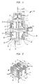
- an electromagnetic actuator is shown, generally indicated 10, having electromagnet core assemblies provided in accordance with the principles of the present invention.
- the electromagnetic actuator 10 includes an upper housing assembly, generally indicated at 12, containing an upper electromagnet 14, and a lower housing assembly, generally indicated at 16, containing a lower electromagnet 18.
- Each electromagnet 14 and 18 includes a core assembly, generally indicated at 20, and a coil assembly 22.
- a generally rectangular armature 24 is arranged for movement between the electromagnets 14 and 18.
- the armature 24 is carried by a reciprocating shaft 26
- the shaft 26 is configured to be coupled to a stem of a gas exchange valve (not shown) of an engine of a vehicle in the conventional manner.
- a pair of opposing springs are associated with the armature 24.
- One spring 27 is shown in FIG. 1.
- the other spring (not shown) is disposed near the cylinder valve.
- the core assembly 20 is shown provided in accordance with the principles of the present invention.
- the core assembly 20 comprises a plurality of laminations 28 stacked with respect to a stacking axis A.
- the laminations generally have the same thickness B in a direction along the stacking axis A and are preferably composed 29 gage M15 C5 soft magnetic material. Other suitable materials of various gages may be employed for the lamination.
- Each lamination 28 is generally E-shaped defining channels 32 to receive the associated coil assembly 22 (FIG. 1).
- the solid center core member 30 has ends 31 and 33, a top surface 38 and a bottom surface 40.
- the center core member 30 is also of E-shape, is composed of silicon iron, and has a thickness C of about 8-12 mm. In the illustrated embodiment, the center core member 30 is composed of 2.5% silicon iron and has a thickness of about 10 mm.
- the core member 30 also includes a center aperture 32 therethrough extending from the top surface 38 to the bottom surface 40. The aperture 32 receives a bushing 34, press-fitted therein.
- the aperture 32 is disposed generally perpendicular to the stacking axis A.
- the bushing 34 supports the reciprocating shaft 26 (FIG. 1).
- the core member 30 may also include one or more apertures 36 for receiving a support pin 37. The support pin(s) are received in apertures in the armature 24 to provide additional support of the reciprocating armature 24 and thus prevent twisting thereof.
- the laminations 28 and core member may be secured together by a weld 42 on each side thereof. It can be appreciated that the laminations 28 may be joined in any other conventional manner, such as, for example, an interlocking or mechanical upset arrangement, gluing, riveting or a combination of these techniques. After assembly, surfaces 38 and 40 of the core assembly are machined so as to be substantially parallel.
- Pins 39 are disposed through apertures 41 in the core assembly 20 to secure the core assembly 20 to the housing assembly 16.
- the stacked laminations 28 provide a high efficiency core by minimizing eddy current losses, while the solid core member allows for easy machining of surfaces 38 and 40 and provides good support of the press-fit bearing 34 disposed in the aperture 32 of the core member 30.
- the solid core member 30 may include oil passages therein to lubricate the bearing 34 via oil galley 43.
Landscapes
- Physics & Mathematics (AREA)
- Electromagnetism (AREA)
- Engineering & Computer Science (AREA)
- Power Engineering (AREA)
- Mechanical Engineering (AREA)
- General Engineering & Computer Science (AREA)
- Valve Device For Special Equipments (AREA)
- Magnetically Actuated Valves (AREA)
- Electromagnets (AREA)
Claims (14)
- Ensemble formant noyau pour actionneur électromagnétique, l'ensemble formant noyau (20) comprenant : une pluralité de tôles empilées (28) s'étendant suivant un axe d'empilage (A), lesdites tôles ayant chacune autant dire la même épaisseur (B) dans une direction suivant l'axe d'empilage, et un élément formant tôle de noyau monobloc (30) comportant des extrémités opposées (31, 33), ledit élément formant noyau étant disposé autant dire centralement par rapport à ladite pluralité de tôles empilées de telle sorte que chaque extrémité dudit élément formant noyau soit en contact avec une tôle de ladite pluralité de tôles, ledit élément formant noyau ayant une épaisseur (C) dans une direction suivant ledit axe d'empilage sensiblement plus grande que l'épaisseur d'une tôle, ledit élément formant noyau comportant une ouverture centrale (32) le traversant disposée autant dire perpendiculairement audit axe d'empilage, caractérisé en ce que l'élément formant noyau comprend au moins une broche (37) s'étendant dudit noyau monobloc dans une direction autant dire perpendiculaire audit axe d'empilage, laquelle broche est censée empêcher la torsion d'un induit à mouvement de va-et-vient (24).
- Ensemble formant noyau selon la revendication 1, comprenant en outre une bague (34) disposée dans ladite première ouverture.
- Ensemble formant noyau selon la revendication 1, dans lequel chacune desdites tôles et ledit élément formant noyau ont une forme autant dire en E.
- Ensemble formant noyau selon la revendication 1, dans lequel ledit élément formant noyau est composé de ferrosilicium.
- Ensemble formant noyau selon la revendication 1, dans lequel les extrémités dudit ensemble formant noyau qui sont perpendiculaires audit axe d'empilage sont usinées pour être sensiblement parallèles.
- Actionneur électromagnétique à monter sur une culasse de cylindre de moteur, l'actionneur (10) comprenant : un premier et un second électro-aimants (14, 18) disposés dans une relation d'espacement, chacun desdits électro-aimants comprenant un ensemble formant noyau (20) et une bobine (22) associée à l'ensemble formant noyau, chaque ensemble formant noyau comprenant : une pluralité de tôles empilées (28) s'étendant suivant un axe d'empilage (A), lesdites tôles ayant chacune autant dire la même épaisseur (B) dans une direction suivant ledit axe d'empilage, un élément formant noyau monobloc (30) comportant des extrémités opposées (31, 33), ledit élément formant noyau étant disposé autant dire centralement par rapport à ladite pluralité de tôles empilées de telle sorte que chaque extrémité dudit élément formant noyau est en contact avec une tôle de ladite pluralité de tôles, ledit élément formant noyau ayant une épaisseur (C) dans une direction suivant ledit axe d'empilage sensiblement plus grande que l'épaisseur d'une tôle, ledit élément formant noyau comportant une ouverture centrale (32) le traversant disposée autant dire perpendiculairement audit axe d'empilage, et une bague (34) dans ladite ouverture, un induit (24) pour aller et venir entre lesdits électro-aimants, et un arbre (26) accouplé audit induit et supporté pour aller et venir dans lesdites bagues, caractérisé en ce que ledit élément formant noyau monobloc comprend au moins une broche (37) s'en étendant dans une direction perpendiculaire audit axe d'empilage et en ce que ledit induit comprend au moins une ouverture pour recevoir ladite broche de telle sorte que ladite broche puisse guider ledit induit lors du mouvement de celui-ci.
- Actionneur électromagnétique selon la revendication 6, dans lequel chacune desdites tôles et ledit élément formant noyau sont de forme autant dire en E.
- Actionneur électromagnétique selon la revendication 7, dans lequel ladite ouverture centrale est disposée dans une jambe centrale de ladite forme en E.
- Actionneur électromagnétique selon la revendication 6, dans lequel ledit élément formant noyau est composé de ferrosilicium.
- Actionneur électromagnétique selon la revendication 6, dans lequel les extrémités dudit ensemble formant noyau qui sont perpendiculaires audit axe d'empilage sont usinées pour être sensiblement parallèles.
- Procédé d'aménagement d'un ensemble formant noyau pour actionneur électromagnétique, le procédé comprenant : l'aménagement d'un élément formant noyau central monobloc (30) comportant une première et une seconde extrémités (31, 33) et ayant une certaine épaisseur (C) définie entre lesdites extrémités, ledit noyau comportant des surfaces supérieure et inférieure (38, 40) et une ouverture centrale (32) le traversant s'étendant de ladite surface supérieure à ladite surface inférieure, l'empilement d'une pluralité de tôles (28) de sorte qu'elles s'étendent vers l'extérieur depuis chaque extrémité dudit élément formant noyau, chacune de ladite pluralité de tôles ayant une épaisseur (B) sensiblement moindre que ladite certaine épaisseur (C), et la jonction de ladite pluralité de tôles les unes aux autres et audit élément formant noyau pour définir l'ensemble formant noyau, caractérisé en ce que l'on prévoit au moins une broche (37) s'étendant de l'élément formant noyau dans une direction perpendiculaire à un axe d'empilage (A) et en ce que l'on pratique dans un induit au moins une ouverture pour recevoir ladite broche de telle sorte que ladite broche puisse guider ledit induit lors du mouvement de celui-ci.
- Procédé selon la revendication 11, dans lequel ladite jonction comprend l'exécution d'une opération de soudage suivant une direction d'empilage desdites tôles.
- Procédé selon la revendication 11, comprenant en outre l'usinage des surfaces supérieure et inférieure dudit ensemble formant noyau de sorte qu'elles soient sensiblement parallèles.
- Procédé selon la revendication 11, comprenant en outre le placement d'une bague dans ladite ouverture de l'élément formant noyau.
Applications Claiming Priority (4)
| Application Number | Priority Date | Filing Date | Title |
|---|---|---|---|
| US6914497P | 1997-12-09 | 1997-12-09 | |
| US69144P | 1997-12-09 | ||
| US181206 | 1998-10-28 | ||
| US09/181,206 US6049264A (en) | 1997-12-09 | 1998-10-28 | Electromagnetic actuator with composite core assembly |
Publications (2)
| Publication Number | Publication Date |
|---|---|
| EP0923091A1 EP0923091A1 (fr) | 1999-06-16 |
| EP0923091B1 true EP0923091B1 (fr) | 2004-08-18 |
Family
ID=26749731
Family Applications (1)
| Application Number | Title | Priority Date | Filing Date |
|---|---|---|---|
| EP98123242A Expired - Lifetime EP0923091B1 (fr) | 1997-12-09 | 1998-12-07 | Actionneur électromagnétique à ensemble de noyaux composites |
Country Status (4)
| Country | Link |
|---|---|
| US (1) | US6049264A (fr) |
| EP (1) | EP0923091B1 (fr) |
| JP (1) | JPH11273945A (fr) |
| DE (1) | DE69825713T2 (fr) |
Families Citing this family (27)
| Publication number | Priority date | Publication date | Assignee | Title |
|---|---|---|---|---|
| DE10002628A1 (de) * | 2000-01-22 | 2001-07-26 | Heinz Leiber | Elektromagnet |
| JP4592159B2 (ja) * | 2000-06-30 | 2010-12-01 | 三菱重工業株式会社 | 電磁クラッチおよび該電磁クラッチを備えた圧縮機 |
| US6798323B2 (en) * | 2001-09-20 | 2004-09-28 | Siemens Energy & Automation, Inc. | Welded AC electromagnet lamination assembly incorporating shading coil |
| US20040113731A1 (en) * | 2002-10-09 | 2004-06-17 | David Moyer | Electromagnetic valve system |
| US20050046531A1 (en) * | 2002-10-09 | 2005-03-03 | David Moyer | Electromagnetic valve system |
| US20050001702A1 (en) * | 2003-06-17 | 2005-01-06 | Norton John D. | Electromechanical valve actuator |
| US7307502B2 (en) * | 2003-07-16 | 2007-12-11 | Marvell World Trade Ltd. | Power inductor with reduced DC current saturation |
| US7023313B2 (en) * | 2003-07-16 | 2006-04-04 | Marvell World Trade Ltd. | Power inductor with reduced DC current saturation |
| US7489219B2 (en) * | 2003-07-16 | 2009-02-10 | Marvell World Trade Ltd. | Power inductor with reduced DC current saturation |
| US7872454B2 (en) * | 2003-08-21 | 2011-01-18 | Marvell World Trade Ltd. | Digital low dropout regulator |
| US7760525B2 (en) * | 2003-08-21 | 2010-07-20 | Marvell World Trade Ltd. | Voltage regulator |
| US20050076866A1 (en) * | 2003-10-14 | 2005-04-14 | Hopper Mark L. | Electromechanical valve actuator |
| US8324872B2 (en) * | 2004-03-26 | 2012-12-04 | Marvell World Trade, Ltd. | Voltage regulator with coupled inductors having high coefficient of coupling |
| FR2870629B1 (fr) * | 2004-05-19 | 2006-09-01 | Johnson Controls Tech Co | Actionneur electromagnetique avec un electroaimant a aimant comportant un noyau unitaire |
| US7190152B2 (en) * | 2004-07-13 | 2007-03-13 | Marvell World Trade Ltd. | Closed-loop digital control system for a DC/DC converter |
| JP4635598B2 (ja) * | 2004-12-17 | 2011-02-23 | 株式会社デンソー | 点火コイル |
| US7305943B2 (en) * | 2005-02-23 | 2007-12-11 | Visteon Global Technologies, Inc. | Electromagnet assembly for electromechanical valve actuators |
| DE102006006031B4 (de) | 2005-04-20 | 2009-12-24 | Bürkert Werke GmbH & Co. KG | Elektromagneteinheit sowie Verfahren zur Herstellung einer solchen Elektromagneteinheit und eines Magnetgehäuses für eine solche Elektromagneteinheit |
| JP5366599B2 (ja) * | 2009-03-13 | 2013-12-11 | 三菱電機株式会社 | 電磁石およびこれを用いた開閉装置 |
| FR2977363B1 (fr) * | 2011-06-30 | 2014-02-28 | Dav | Module d'interface tactile a retour haptique |
| US9599246B2 (en) * | 2015-08-05 | 2017-03-21 | Dayco Ip Holdings, Llc | Magnetically actuated shut-off valve |
| JP6575343B2 (ja) | 2015-12-11 | 2019-09-18 | オムロン株式会社 | リレー |
| JP6421745B2 (ja) * | 2015-12-11 | 2018-11-14 | オムロン株式会社 | リレー |
| EP3222914B1 (fr) * | 2016-03-23 | 2019-01-09 | Orkli, S. Coop. | Valve de sécurité à gaz |
| IT201700094491A1 (it) * | 2017-08-18 | 2019-02-18 | General Electric Technology Gmbh | Reattore. |
| US10726985B2 (en) * | 2018-03-22 | 2020-07-28 | Schaeffler Technologies AG & Co. KG | Multi-stage actuator assembly |
| KR102765667B1 (ko) * | 2024-09-03 | 2025-02-12 | (주)에스엠테크 | 솔레노이드 구조체 제조 방법 및 코어부 용접장치 |
Family Cites Families (13)
| Publication number | Priority date | Publication date | Assignee | Title |
|---|---|---|---|---|
| FR1592884A (fr) * | 1968-02-28 | 1970-05-19 | ||
| US3577109A (en) * | 1968-09-18 | 1971-05-04 | Allis Chalmers Mfg Co | Magnetic shielding construction for electric transformers |
| DE2223116C3 (de) * | 1972-05-12 | 1981-04-23 | Licentia Patent-Verwaltungs-Gmbh, 6000 Frankfurt | Zusammengesetzter magnetischer Ringkern |
| DE2324644A1 (de) * | 1973-05-16 | 1974-12-05 | Schorsch Gmbh | Schichtkern mit wicklungspresskonstruktion und auf schenkeln des kerns angeordneten wicklungen fuer transformatoren oder drosselspulen |
| US4009460A (en) * | 1974-09-24 | 1977-02-22 | Hitachi Metals, Ltd. | Inductor |
| JPS63241905A (ja) * | 1987-03-27 | 1988-10-07 | Sumitomo Special Metals Co Ltd | 磁界発生装置 |
| JP2653160B2 (ja) * | 1989-03-13 | 1997-09-10 | 株式会社デンソー | 電磁弁 |
| US5371486A (en) * | 1990-09-07 | 1994-12-06 | Kabushiki Kaisha Toshiba | Transformer core |
| US5636601A (en) * | 1994-06-15 | 1997-06-10 | Honda Giken Kogyo Kabushiki Kaisha | Energization control method, and electromagnetic control system in electromagnetic driving device |
| AU4237096A (en) * | 1994-11-09 | 1997-05-29 | Aura Systems, Inc. | Hinged armature electromagnetically actuated valve |
| DE29514508U1 (de) * | 1995-09-09 | 1995-11-02 | Vacuumschmelze Gmbh, 63450 Hanau | Blechpaket für Magnetkerne zum Einsatz in induktiven Bauelementen mit einer Längsöffnung |
| EP0795881B1 (fr) * | 1996-03-11 | 1999-06-09 | Denso Corporation | Dispositif électromagnétique à régulation de position pour stator |
| DE29712502U1 (de) * | 1997-07-15 | 1997-09-18 | FEV Motorentechnik GmbH & Co. KG, 52078 Aachen | Elektromagnetischer Aktuator mit Gehäuse |
-
1998
- 1998-10-28 US US09/181,206 patent/US6049264A/en not_active Expired - Fee Related
- 1998-12-07 DE DE69825713T patent/DE69825713T2/de not_active Expired - Fee Related
- 1998-12-07 EP EP98123242A patent/EP0923091B1/fr not_active Expired - Lifetime
- 1998-12-09 JP JP10350250A patent/JPH11273945A/ja active Pending
Also Published As
| Publication number | Publication date |
|---|---|
| US6049264A (en) | 2000-04-11 |
| JPH11273945A (ja) | 1999-10-08 |
| DE69825713D1 (de) | 2004-09-23 |
| EP0923091A1 (fr) | 1999-06-16 |
| DE69825713T2 (de) | 2005-02-10 |
Similar Documents
| Publication | Publication Date | Title |
|---|---|---|
| US6049264A (en) | Electromagnetic actuator with composite core assembly | |
| US6157277A (en) | Electromagnetic actuator with improved lamination core-housing connection | |
| US6078235A (en) | Electromagnetic actuator and housing therefor | |
| US5690064A (en) | Electromagnetic valve driving apparatus for driving a valve of an internal combustion engine | |
| US5310160A (en) | Electromagnetic valve top part | |
| EP0921536B1 (fr) | Actionneur électromagnétique avec paquet de tôles et boítier connectés en queue d'aronde | |
| JP2638651B2 (ja) | ガス交換弁のための操作装置 | |
| US4700165A (en) | DC electromagnet equipped with a voltage surge damping device | |
| EP0923089B1 (fr) | Actionneur électromagnétique avec boítier en deux parties | |
| US6373361B1 (en) | Core of solenoid actuator | |
| US6420949B1 (en) | Core of solenoid actuator | |
| EP0921280B1 (fr) | Actionneur électromagnétique avec boítier en acier estampé | |
| US6322048B1 (en) | Actuator for electromagnetic valve control | |
| US6798323B2 (en) | Welded AC electromagnet lamination assembly incorporating shading coil | |
| US6691651B2 (en) | Engine valve operating system for internal combustion engine | |
| EP2197012B1 (fr) | Électroaimant pour contacteur électrique | |
| US7305943B2 (en) | Electromagnet assembly for electromechanical valve actuators | |
| JP2003163116A (ja) | 電磁アクチュエータ | |
| KR101313478B1 (ko) | V형 배열로 배치된 영구 자석을 구비한 전자기 액추에이터 | |
| US6236296B1 (en) | Electromagnetic actuator | |
| US7305942B2 (en) | Electromechanical valve actuator | |
| JP2009267078A (ja) | 電磁アクチュエータのアーマチュア | |
| GB2302762A (en) | Electromagnetic valve driving apparatus for driving a valve of an internal combustion engine | |
| JPH10199723A (ja) | ソレノイド用ステータ | |
| JP2009529315A (ja) | 電磁的に好適化されたv字形状の永久磁石を備える電磁アクチュエータ |
Legal Events
| Date | Code | Title | Description |
|---|---|---|---|
| PUAI | Public reference made under article 153(3) epc to a published international application that has entered the european phase |
Free format text: ORIGINAL CODE: 0009012 |
|
| AK | Designated contracting states |
Kind code of ref document: A1 Designated state(s): DE FR IT |
|
| AX | Request for extension of the european patent |
Free format text: AL;LT;LV;MK;RO;SI |
|
| 17P | Request for examination filed |
Effective date: 19991109 |
|
| AKX | Designation fees paid |
Free format text: DE FR IT |
|
| 17Q | First examination report despatched |
Effective date: 20030429 |
|
| GRAP | Despatch of communication of intention to grant a patent |
Free format text: ORIGINAL CODE: EPIDOSNIGR1 |
|
| GRAS | Grant fee paid |
Free format text: ORIGINAL CODE: EPIDOSNIGR3 |
|
| GRAA | (expected) grant |
Free format text: ORIGINAL CODE: 0009210 |
|
| RAP1 | Party data changed (applicant data changed or rights of an application transferred) |
Owner name: SIEMENS VDO AUTOMOTIVE CORPORATION |
|
| AK | Designated contracting states |
Kind code of ref document: B1 Designated state(s): DE FR IT |
|
| REF | Corresponds to: |
Ref document number: 69825713 Country of ref document: DE Date of ref document: 20040923 Kind code of ref document: P |
|
| PGFP | Annual fee paid to national office [announced via postgrant information from national office to epo] |
Ref country code: FR Payment date: 20041223 Year of fee payment: 7 |
|
| ET | Fr: translation filed | ||
| PLBE | No opposition filed within time limit |
Free format text: ORIGINAL CODE: 0009261 |
|
| STAA | Information on the status of an ep patent application or granted ep patent |
Free format text: STATUS: NO OPPOSITION FILED WITHIN TIME LIMIT |
|
| 26N | No opposition filed |
Effective date: 20050519 |
|
| PG25 | Lapsed in a contracting state [announced via postgrant information from national office to epo] |
Ref country code: IT Free format text: LAPSE BECAUSE OF NON-PAYMENT OF DUE FEES;WARNING: LAPSES OF ITALIAN PATENTS WITH EFFECTIVE DATE BEFORE 2007 MAY HAVE OCCURRED AT ANY TIME BEFORE 2007. THE CORRECT EFFECTIVE DATE MAY BE DIFFERENT FROM THE ONE RECORDED. Effective date: 20051207 |
|
| PG25 | Lapsed in a contracting state [announced via postgrant information from national office to epo] |
Ref country code: FR Free format text: LAPSE BECAUSE OF NON-PAYMENT OF DUE FEES Effective date: 20060831 |
|
| REG | Reference to a national code |
Ref country code: FR Ref legal event code: ST Effective date: 20060831 |
|
| PGFP | Annual fee paid to national office [announced via postgrant information from national office to epo] |
Ref country code: DE Payment date: 20081219 Year of fee payment: 11 |
|
| PG25 | Lapsed in a contracting state [announced via postgrant information from national office to epo] |
Ref country code: DE Free format text: LAPSE BECAUSE OF NON-PAYMENT OF DUE FEES Effective date: 20100701 |