EP0923101A2 - Veranderliche thermische und magnetische Struktur für die ausloseeinheit eines Schutzschalters - Google Patents
Veranderliche thermische und magnetische Struktur für die ausloseeinheit eines Schutzschalters Download PDFInfo
- Publication number
- EP0923101A2 EP0923101A2 EP98122705A EP98122705A EP0923101A2 EP 0923101 A2 EP0923101 A2 EP 0923101A2 EP 98122705 A EP98122705 A EP 98122705A EP 98122705 A EP98122705 A EP 98122705A EP 0923101 A2 EP0923101 A2 EP 0923101A2
- Authority
- EP
- European Patent Office
- Prior art keywords
- heating element
- yoke
- armature
- bimetallic
- bimetallic element
- Prior art date
- Legal status (The legal status is an assumption and is not a legal conclusion. Google has not performed a legal analysis and makes no representation as to the accuracy of the status listed.)
- Withdrawn
Links
Images





Classifications
-
- H—ELECTRICITY
- H01—ELECTRIC ELEMENTS
- H01H—ELECTRIC SWITCHES; RELAYS; SELECTORS; EMERGENCY PROTECTIVE DEVICES
- H01H71/00—Details of the protective switches or relays covered by groups H01H73/00 - H01H83/00
- H01H71/10—Operating or release mechanisms
- H01H71/12—Automatic release mechanisms with or without manual release
- H01H71/40—Combined electrothermal and electromagnetic mechanisms
- H01H71/405—Combined electrothermal and electromagnetic mechanisms in which a bimetal forms the inductor for the electromagnetic mechanism
-
- H—ELECTRICITY
- H01—ELECTRIC ELEMENTS
- H01H—ELECTRIC SWITCHES; RELAYS; SELECTORS; EMERGENCY PROTECTIVE DEVICES
- H01H71/00—Details of the protective switches or relays covered by groups H01H73/00 - H01H83/00
- H01H71/10—Operating or release mechanisms
- H01H71/12—Automatic release mechanisms with or without manual release
- H01H71/14—Electrothermal mechanisms
- H01H71/16—Electrothermal mechanisms with bimetal element
- H01H71/164—Heating elements
-
- H—ELECTRICITY
- H01—ELECTRIC ELEMENTS
- H01H—ELECTRIC SWITCHES; RELAYS; SELECTORS; EMERGENCY PROTECTIVE DEVICES
- H01H71/00—Details of the protective switches or relays covered by groups H01H73/00 - H01H83/00
- H01H71/74—Means for adjusting the conditions under which the device will function to provide protection
- H01H71/7409—Interchangeable elements
-
- H—ELECTRICITY
- H01—ELECTRIC ELEMENTS
- H01H—ELECTRIC SWITCHES; RELAYS; SELECTORS; EMERGENCY PROTECTIVE DEVICES
- H01H71/00—Details of the protective switches or relays covered by groups H01H73/00 - H01H83/00
- H01H71/74—Means for adjusting the conditions under which the device will function to provide protection
- H01H71/7463—Adjusting only the electromagnetic mechanism
-
- H—ELECTRICITY
- H01—ELECTRIC ELEMENTS
- H01H—ELECTRIC SWITCHES; RELAYS; SELECTORS; EMERGENCY PROTECTIVE DEVICES
- H01H71/00—Details of the protective switches or relays covered by groups H01H73/00 - H01H83/00
- H01H71/74—Means for adjusting the conditions under which the device will function to provide protection
- H01H2071/749—Means for adjusting the conditions under which the device will function to provide protection with a shunt element connected in parallel to magnetic or thermal trip elements, e.g. for adjusting trip current
Definitions
- the present invention relates generally to a circuit breaker and more particularly to a configurable thermal and magnetic structure for tripping the circuit breaker.
- the thermal component typically includes a bimetallic element which responds to relatively long duration overload conditions to trip the breaker when a specified current level is exceeded for a period of time.
- a typical thermal trip unit at least a portion of the current flowing through the breaker is channeled through the bimetallic element.
- the ohmic resistance of the bimetallic element causes it to generate heat in proportion to the square of the level of current flowing through the breaker.
- the trip mechanism releases a latch which holds the breaker contacts closed. When this latch is released, the breaker contacts open, typically responsive to a relatively strong force.
- a typical magnetic tripping element includes an armature which is attracted by a magnetic field generated by a relatively high magnitude overcurrent flowing through the breaker. This magnetic field is concentrated by a magnetically permeable yoke which surrounds the conductor through which the current flows. When the armature is attracted to the yoke, it also engages the trip mechanism causing the circuit breaker to open. Both thermal and magnetic structures are used in a typical circuit breaker trip unit to enable the breaker to be tripped on a relatively low overload condition having a long duration and to trip quickly in response to a relatively high overcurrent condition.
- thermal and magnetic structures in circuit breaker trip units may be adjusted to accommodate a relatively narrow variation in current magnitude and current flow duration. These adjustments are made by changing the distance between the bimetallic element and the trip bar for a thermal element and by adjusting the separation between the armature and the yoke for a magnetic trip element.
- the present invention is embodied in a thermal and magnetic trip structure which may be configured to accommodate a wide range of overcurrent conditions.
- the exemplary structure includes a thermal trip unit having a bimetallic element and one or more resistive heating elements.
- the heating elements may be configured in series or in parallel with the bimetallic element to respectively increase or decrease the heating effect resulting from a given current level.
- the series connected resistive heating elements may be configured to form an inductance which enhances the magnetic field that attracts the armature to trip the breaker on short duration overcurrent conditions.
- the electromagnetic structure includes one or two magnetically permeable yokes which interact with the heating elements and the bimetallic element to produce an enhanced magnetic field for the operation of the magnetic trip unit.
- the magnetic portion of the trip unit includes two calibration adjustments for each pole of the breaker, the first calibration adjustment adjusts the gap between the armature and the yoke and the second adjustment adjusts the tension of a spring connected to the armature.
- This spring provides a force which must be overcome in order to magnetically trip the breaker.
- the trip unit includes an adjustment bar which may be used to vary the spacing between the armature and the yoke in all poles of the breaker to allow the trip range of the trip unit to be changed in the field.
- the adjustment bar may be used to change the angle of the tension springs for all poles of the breaker to allow the trip range of the circuit breaker to be changed in the field.
- FIG. 1 is an isometric drawing of a circuit breaker which includes an embodiment of the present invention.
- the circuit breaker shown in Figure 1 is a multi-part molded case circuit breaker.
- the breaker 100 includes a cover 110, a trip unit 114 and a switch unit 112.
- the exemplary circuit breaker 100 is a three-phase breaker having three sets of contacts for interrupting current in each of the three respective phases.
- each phase includes separate breaker contacts and a separate trip mechanism.
- the center pole of the circuit breaker includes an operating mechanism which controls the switching of all three poles of the breaker.
- Figure 4 is a cutaway view of the complete circuit breaker along the lines 4 - 4 shown in Figure 1.
- the main components of the circuit breaker are a fixed line contact arm 404 and a moveable load contact arm 402.
- the operating mechanism 312 may be controlled by a toggle handle 408 to manually open and close the contact arms 402 and 404.
- a cradle 436 of the operating mechanism 406 engages a latch 434.
- the cradle 463 pushes up against a latch surface of the latch 434 with a force of approximately 40 pounds.
- the latch 434 is released, releasing the cradle 436 and opening the contact arms 402 and 404.
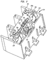
- FIG 2 is an isometric drawing of the trip unit 114 with the cover 110 removed.
- each of the breaker poles includes a separate bimetallic element 210.
- the bimetallic element 210 in any of the breaker poles is heated by, for example, a relatively long duration but low magnitude overcurrent, the bimetallic element deflects to engage a surface 220A on a trip bar 220.
- the bimetallic element 210 deflects further its pressure on the surface 220A causes the trip bar 220 to rotate in a counterclockwise direction. This rotation releases a latch 216 which holds a latch kicker 212 in place.
- the latch kicker 212 As the latch 216 is rotated in a counterclockwise direction, the latch kicker 212, is released and is allowed to rotate in a counterclockwise direction responsive to the force exerted on it by a torsion spring 214. As described below, it is the motion of the latch kicker 212 which trips the breaker, ultimately causing the contacts 402 and 404 (shown in Figure 4) to open.
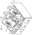
- FIG 3 is an isometric drawing of the switch unit 112 of the circuit breaker 100 with the cover 110 removed.
- the circuit breaker shown in Figure 3 includes an intermediate latch bar 314 having a trip foot 310 which is engaged by the latch kicker 212 when the breaker trips.
- the latch kicker 212 As the latch kicker 212 is released and rotates in a counterclockwise direction, it hits the trip foot 310 of the intermediate trip bar 314, causing it to rotate in a counterclockwise direction.
- the rotation of the secondary trip bar 314 releases a latch which allows the operating mechanism of the breaker to open the load and line contacts in each of the three breaker poles.
- current is applied to the breaker 100 at a line terminal 400.
- the current flows through the line terminal to a line contact arm 404 and then through a load contact arm 402.
- the load contact arm 402 is connected to a copper bus 430 which couples the current to the trip unit 114.
- the current flows through heating elements 414 which, in the exemplary configuration, are separated by an insulating element 416.
- the heating elements 414 are mechanically coupled to a bimetallic element 210 which, during an overcurrent condition, deflects to engage the surface 220A of the trip bar 220.
- the bimetallic element 210 is coupled to a load terminal 428 to provide current from the circuit breaker 100 to a load device.
- the exemplary trip unit includes a magnetic trip mechanism.
- This trip mechanism includes a yoke 412, which surrounds the heating elements 416 and bimetallic element 210, and an armature 410 that, during a large overcurrent condition, is attracted by magnetic forces generated by the current flowing through the heating units and bimetallic element and concentrated by the yoke 412.
- the armature 410 is coupled to a rating and calibration bar 420 by a spring 418.
- the armature 410 is drawn toward the yoke 412 and engages the lower arm 220B of the trip bar 220. This rotates the tripbar 220 in a counterclockwise direction causing it to disengage latch 216 from latch kicker 212 (both shown in Figure 2).
- latch kicker 212 when latch kicker 212 is released, it engages secondary latch bar 314 causing it to release latch 434.
- Latch 434 when in the engaged position, holds cradle element 436 of the operating mechanism 312.
- the cradle element 436 pushes up against the latch surface of the latch 434 with a force of approximately 40 pounds.
- cradle element 436 rotates in a clockwise direction causing the operating mechanism 312 to open the connection between the load contact arm 402 and the line contact arm 404.
- the rating of the breaker (i.e. the current at which the breaker will trip) may be adjusted by turning an adjustment screw 222.
- screw 222 When screw 222 is turned, a cam 425 rotates, causing the trip bar 220 to rotate relative to the latch 216. This rotation moves the contact surface 220A closer to the bimetallic element 210, allowing a lower level thermal deflection of the bimetallic element 210 to trip the breaker.
- the performance of the magnetic portion for all poles of the trip unit may also be adjusted using an adjustment knob 224 (shown in Figure 2) which rotates the rating and calibration bar 420.
- the rating and calibration bar 420 includes a biasing spring (not shown) which biases the bar for rotation in a counterclockwise direction.
- the magnetic trip performance of each pole may be individually calibrated using adjustment screws 422 and 424.
- FIG. 5 is an isometric drawing of a portion of an exemplary thermal and magnetic trip unit, suitable for use with the present invention.
- the thermal trip mechanism includes two heating elements 414, an insulating element 416 and the bimetallic element 210.
- Each of the heating elements 414 and the insulating element 416 are in an inverted "U” shape such that current flows through each of the elements from one leg of the "U" to the other leg.
- the bimetallic element includes a lower portion which is in an inverted "U” shape. Current being provided by the breaker flows through this lower portion of the bimetallic element.
- the bimetallic element also includes a protruding member 210a which extends from the top portion of the inverted "U” shape.
- the exemplary bimetallic element 210 may be made from any of a number of pairs of materials exhibiting different thermal expansion characteristics.
- the choice of the materials affects the amount by which the member 210a is deflected when the bimetallic element is heated as well as the current level required to produce a particular temperature.
- Relatively expensive materials may be needed to produce a bimetallic strip which exhibits a particular level of deflection at a specified current level.
- the subject invention allows flexibility in the configuration of the thermal and magnetic tripping mechanisms precisely controlled levels of thermal and magnetic tripping currents may be handled using relatively inexpensive materials.
- one exemplary yoke structure 412 which may be used by a circuit breaker conforming to the subject invention, includes two yoke elements 412a and 412b, each wrapped around a respective leg of the inverted "U" shaped combination of the heating elements 414 and bimetallic element 210. As described below, this configuration of the yoke 412 causes a relatively high magnetic force to be generated at relatively low current levels.
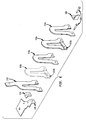
- FIG. 6 is an exploded isometric diagram showing the construction of an exemplary thermal unit of the thermal and magnetic trip unit shown in Figure 2.
- the bus 430 is physically connected to a first heating element 414, a first insulating element 416, a second heating element 414, a second insulating element 416 and the bimetallic element 210 via insulating rivets 610.
- Current is conveyed from the first heating element 414a to the second heating element 414B via a bus 612 which crosses from one side of the insulator 416a to the other side.
- the rivets 610 also connect the thermal structure to the load terminal 428 and to a structural coupling 614, which is not electrically connected to the circuit breaker mechanism.
- This structure may be configured in several ways to produce different heating (and tripping) effects.
- one of the heating elements 414 and one of the insulating elements 416 may be deleted. In this configuration, assuming the same materials as in the first configuration, a larger current flow may be needed to produce the same amount of heat and thus the same deflection of the bimetallic element 210.
- the insulating elements 416 and busses 612 may be removed. In this configuration, the heating elements 414a and 414b are electrically configured in parallel with the bimetallic element 210. The current flow through each of the heating elements 414a and 414b and the bimetallic element 210 is in proportion to their respective conductivities.
- This configuration would further increase the amount of current needed to produce a given deflection of the bimetallic element as the heating elements 414a and 414b would act to shunt current that would otherwise flow through the bimetallic element 210 and, because the current flowing through each of the heating elements 414 would be less than the current flow through the elements shown in Figure 6, the combination of the heating elements 414 and bimetallic element 210 would not generate the same level of heat as the structure shown in Figure 6 for the same current flow.
- one of the insulating elements for example 416a and the corresponding bus element 612a may remain while the other insulating element, 416b and bus element 612b is removed.
- one heating element 414a is connected in series with a parallel combination of the other heating element 414b and the bimetallic element 210.
- This configuration would provide the additional heating effect of the first heating element 414A while protecting the bimetallic element 210 from overheating through use of the second heating element 414b as a current shunt.
- the choice of materials for the heating elements 414 and the bimetallic element 210 influences the operating characteristics of the thermal unit.
- the heating elements 414a and 414b are copper and the bimetallic element is a combination of copper and steel.
- the exemplary insulators 416a and 416b are a flexible glass-melamine composition.
- the structure of the thermal unit shown in Figure 6, also influences the operation of the magnetic unit.
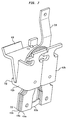
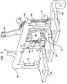
- Figures 7 and 8 are isometric drawings which show rear and front views of the combined thermal structure, yoke 412 and armature 410.
- two heating elements 414 are separated by an insulator 416.
- the second heating element 414b is coupled in parallel with the bimetallic element 210.
- the thermal and magnetic structure shown in Figures 7 and 8 includes two yoke elements 412a and 412b. Each of these yoke elements surrounds a respectively different arm of the inverted "U" thermal structure.
- the yokes 412a and 412b concentrate the magnetic field generated from the coil formed by the series connected heating element 414a, the bus element 612, the parallel connected heating element 414b and the bimetallic element 210.
- the armature 410 rests in a holder 710 formed on the front of the yokes 412a and 412b.
- the gap between the armature 410 and the yoke structure 412a and 412b defines a level of magnetic force needed to trip the breaker. As described above, this level of magnetic force is generated by current flowing through the heating elements 414 and bimetallic element 210.
- the magnetic structure shown in Figures 7 and 8 is also adjustable to achieve a number of different characteristics for the breaker.
- the number of turns provided by the thermal structure may be adjusted by inserting or removing insulating elements 416 and bus elements 612.
- the magnetic field generated by the thermal structure increases with the increase in the number of turns.
- the performance of the magnetic structure may also be changed by removing one of the yokes, for example 412a, and providing a smaller armature 410, as shown, for example in Figure 9.
- the use of one yoke, for example 412b results in an approximate halving of the magnetic field generated by thermal and magnetic structure.
- the operation of the magnetic structure may be affected by changing the gap between the armature 410 and yoke 412 as well as by changing the angle at which the spring 418 (shown in Figure 4) acts against the armature 410.
- Figures 9 and 10 are isometric drawings which show the thermal and magnetic structure for the center pole of the circuit breaker 100 while showing the load contacts 428 for each of the three poles and the common adjustment bar 420. Although not shown in Figures 9 and 10, each of the outer poles of the breaker has a thermal and magnetic structure which is identical to that shown for the center pole.
- the adjustment bar 420 is shown as a sideways “E", having three legs 423, one for each pole of the breaker.
- the adjustment bar 420 is coupled to a biasing spring (not shown) and is configured to pivot about an axis 910 in the circuit breaker 100.
- the biasing spring for the adjustment bar 420 may be, for example, a torsion spring which biases the arm 420 for rotation in a counterclockwise direction about the axis 910.
- the adjustment bar 420 includes a tab 421 which extends in a generally upward direction from the top surface of the bar 420. The tab 421 engages an adjustment cam 425 (shown in Figures 2 and 11).
- the adjustment cam 425 when turned, rotates the adjustment bar 420 about the axis 910, causing the legs 423 to move closer to or farther away from their respective thermal and magnetic structures.
- the adjustment bar 420 As the adjustment bar 420 is rotated, the top of the armature 410 moves closer to the yoke 412 or farther away from the yoke 412, respectively decreasing or increasing the gap between the armature 410 and yoke 412.
- the biasing springs 418 are rotated, changing the angle of the springs 418 with respect to the armatures 410. This change in angle changes the torque that the armature must generate in order to engage the yoke 412.
- the adjustment knob 224 and adjustment cam 425 may be used to change both the armature gap and force in order to adjust the trip level of the circuit breaker between minimum and maximum settings.
- the three legs 423 of the exemplary adjustment bar 420 are used to calibrate the respective magnetic structures in each of the three poles of the circuit breaker 100.
- the leg 423 for the center pole of the adjustment bar 420 includes 2 calibration screws 422 and 424.
- Calibration screw 424 when turned, moves the upper portion of the armature 410 closer to or farther away from the yoke 412, effectively adjusting the gap between the armature and the yoke.
- the calibration screw 422 when turned, adjusts the tension of the biasing spring 418, which is connected to the upper portion of the armature, pulls the armature 410 toward the respective leg 423 of the calibration and adjustment arm 420.
- each pole of the breaker may be separately calibrated to have a precisely defined gap and spring tension which produces a tripping of the breaker at a desired current level.
- the adjustment knob 224 and cam 425 may be used, as described above, to rotate the entire adjustment bar 420 to effect a change in the magnitude of the trip level for all poles of the breaker.
- the calibration screws on the legs 423 of the calibration and adjustment bar 420 operate as shown in Figure 10.
- calibration screw 422 When calibration screw 422 is turned, the end of the exemplary spring 418 attached to the adjustment screw is pulled toward the respective leg 423 of the calibration and adjustment bar 420, increasing the angle between the spring and the armature 410.
- the calibration screw 424 (shown in Figure 9) pushes directly against a tab 410a on the armature 410.
- this screw is advanced, the gap between the armature 410 and the yoke 412 decreases; as the screw is retracted, the gap between the armature and yoke increases.
- the magnetic structure for all poles of the breaker may be adjusted as follows.
- the adjustment bar 420 is rotated in a clockwise direction by the cam 425 (shown in Figure 11)
- the separation between the armatures 410 and the yokes 412 increases for all poles of the breaker 100 as does the angle at which the respective springs 418 act against the armatures 410.
- the adjustment bar 420 is rotated in a counterclockwise direction, the distance between the armature 410 and the yoke 412 decreases and the angle of the spring 418 also decreases.
- the armature 410 includes a second tab, 410b, which engages the trip bar. It is this tab which pushes against the lower surface 220b of the trip bar 220 when the magnetic structure of at least one pole trips the circuit breaker 100.
- FIG 11 is a cutaway side plan view, taken along lines 4 - 4, shown in Figure 1, of the circuit breaker trip unit 114.
- Figure 11 shows the thermal and magnetic structure, the adjustment bar 420 and the trip bar 220.
- the trip unit would operate as follows. Current flowing from the bus 430 flows through the heating elements 414, which are connected by the bus element 612 and through the bimetallic element 210, causing the bimetallic element to deflect toward the surface 220a of the trip bar 220. As the bimetallic element makes contact with the surface 220a, the trip bar 220 rotates in a counterclockwise direction, raising the latch 216 causing it to disengage from the latch kicker 212 (shown in Figure 2). As described above, the amount of current needed to produce the deflection of the bimetallic element 210 which disengages the latch kicker 212 may be adjusted by changing the number of heating elements and the number of insulators.
- the largest deflection for the smallest amount of current is produced having two heating elements 412, two insulating elements 416 and two connecting bus elements 612 such that the heating elements are connected in series with the bimetallic element and form a coil having almost three complete turns.
- the maximum configuration is produced with no insulating elements 416 and the two (or three) heating elements coupled in parallel with the bimetallic element 210.
- the deflection of the bimetallic element needed to trip the breaker may be adjusted by adjusting the separation between the surface 220a and bimetallic element 210. As described above with reference to Figures 2 and 4 this adjustment may be accomplished using the adjustment knob 224 which rotates the cam surface 425 (both shown in Figure 2).
- Table 1 shows several different configurations of the thermal unit arranged such that the first entry produces the proper deflection of the bimetallic element 210 for a low rated current and the last entry produces the proper deflection for a high rated current.
- heating elements 414 Insulators 416 series parallel 3 3 3 0 2 2 2 0 1 1 1 0 0 0 0 0 1 0 0 1 2 1 1 1 3 2 2 1 2 0 0 2 3 1 1 2 3 0 0 3
- the columns “series” and “parallel” describe, respectively, the number of heating elements 414 which are configured in series with the bimetallic element 210 (using an insulator 416 and a connecting bus element 612, as shown in Figure 6) and the number of heating elements 414 which are connected in parallel with the bimetallic element 210 without interstitial insulators 416.
- the magnetic structure of the thermal and magnetic trip unit operates to trip the breaker.
- This structure operates as follows. As current flows from the bus 430 through the thermal structure formed by the heating elements 414, connecting bus element 612 insulator 416 and bimetallic element 210, it generates a magnetic field which is concentrated by the yoke 412 (or yokes 412a and 412b). This magnetic field increases with an increase in the level of current flowing through the breaker and, when a threshold current level is reached, generates a magnetic force which causes at least one of the armatures 410 to move toward the respective yoke 412.
- the tab 410b on the armature 410 engages a protrusion 220b on the bottom of the trip bar 220.
- the trip bar 220 rotates in a counterclockwise direction raising the latch 216 to release the latch kicker 212.
- the operation of the magnetic portion of the thermal and magnetic trip unit may be adjusted by changing the number of insulators and heating elements used in the thermal structure to increase the number of turns for the current flowing through the thermal structure and thus the magnetic field generated by that current.
- the magnetic field generated for a given current level may be increased by including two yoke units 412a and 412b instead of a single yoke unit.
- the amount of magnetic force needed to attract the armature 410 to the yoke 412 may be increased or decreased by increasing or decreasing the gap between the armature 410 and yoke 412 and by increasing or decreasing the angle at which the biasing spring 418 acts against the armature 410.
- one turn is formed by the bimetallic element 210 or by a combination of a heating element 414, connecting bus element 612 and insulator 416, as shown in Figure 6.
- the thermal unit has only one turn if no heating elements 414 exist or if all of the heating elements 414 are connected in parallel with the bimetallic element 210 (i.e. without interstitial insulators). While the invention has been described in terms of an exemplary embodiment, it is contemplated that it may be practiced as outlined in the above within the scope of the appended claims. For example, while tables 1 and 2 show a maximum of three heating elements 414 and three insulators 416, it is contemplated that a larger number may be used within the scope of the present invention.
Landscapes
- Physics & Mathematics (AREA)
- Electromagnetism (AREA)
- Engineering & Computer Science (AREA)
- Power Engineering (AREA)
- Breakers (AREA)
Applications Claiming Priority (2)
| Application Number | Priority Date | Filing Date | Title |
|---|---|---|---|
| US988060 | 1992-12-09 | ||
| US08/988,060 US5872495A (en) | 1997-12-10 | 1997-12-10 | Variable thermal and magnetic structure for a circuitbreaker trip unit |
Publications (2)
| Publication Number | Publication Date |
|---|---|
| EP0923101A2 true EP0923101A2 (de) | 1999-06-16 |
| EP0923101A3 EP0923101A3 (de) | 2000-03-01 |
Family
ID=25533815
Family Applications (1)
| Application Number | Title | Priority Date | Filing Date |
|---|---|---|---|
| EP98122705A Withdrawn EP0923101A3 (de) | 1997-12-10 | 1998-11-30 | Veranderliche thermische und magnetische Struktur für die ausloseeinheit eines Schutzschalters |
Country Status (2)
| Country | Link |
|---|---|
| US (1) | US5872495A (de) |
| EP (1) | EP0923101A3 (de) |
Cited By (6)
| Publication number | Priority date | Publication date | Assignee | Title |
|---|---|---|---|---|
| WO2006017426A1 (en) * | 2004-08-03 | 2006-02-16 | Siemens Energy & Automation, Inc. | Systems, methods, and device for actuating a circuit breaker |
| WO2006050775A1 (de) * | 2004-11-10 | 2006-05-18 | Abb Patent Gmbh | Thermischer auslöser |
| DE102005047549A1 (de) * | 2005-09-30 | 2007-04-19 | Siemens Ag | Schalter zur Schaltung mindestens eines elektrischen Stromes |
| WO2007082775A1 (de) * | 2006-01-23 | 2007-07-26 | Siemens Aktiengesellschaft | Verfahren zur erweiterung des einstellbereiches von überlastschutzeinrichtungen, zugehörige überlastschutzeinrichtungen und deren verwendung |
| CN102280322A (zh) * | 2010-06-08 | 2011-12-14 | 伊顿工业有限公司 | 用于断路器的脱扣单元 |
| DE102006042187B4 (de) * | 2006-09-08 | 2016-11-03 | Ls Industrial Systems Co., Ltd. | Unmittelbarer Auslösemechanismus für einen mit einem gegossenen Gehäuse versehenen Leistungsschalter |
Families Citing this family (31)
| Publication number | Priority date | Publication date | Assignee | Title |
|---|---|---|---|---|
| US6326869B1 (en) * | 1999-09-23 | 2001-12-04 | General Electric Company | Clapper armature system for a circuit breaker |
| US6274833B1 (en) * | 2000-02-18 | 2001-08-14 | Siemens Energy & Automation, Inc. | Plug-in trip unit joint for a molded case circuit breaker |
| US6897747B2 (en) * | 2002-05-10 | 2005-05-24 | Joseph T. Brandon | Circuit breaker |
| US6879228B2 (en) * | 2003-02-05 | 2005-04-12 | Eaton Corporation | Circuit breaker including magnetic trip mechanism |
| US6759931B1 (en) * | 2003-02-05 | 2004-07-06 | Eaton Corporation | Magnetic member, circuit breaker employing the same, and method of manufacturing the same |
| ATE535929T1 (de) * | 2006-04-28 | 2011-12-15 | Siemens Industry Inc | Vorrichtungen, systeme und verfahren zum sperren eines schutzschalters |
| DE102007010944A1 (de) * | 2006-06-14 | 2007-12-20 | Moeller Gmbh | Thermischer und/oder magnetischer Überlastauslöser |
| US20080122563A1 (en) * | 2006-08-28 | 2008-05-29 | Ls Industrial Systems Co., Ltd. | Instantaneous trip mechanism for mould cased circuit breaker |
| FR2906643B1 (fr) * | 2006-09-29 | 2008-12-26 | Ls Ind Systems Co Ltd | Mecanisme de declenchement instantane pour coupe-circuit a boitier moule. |
| ITBG20060065A1 (it) * | 2006-12-21 | 2008-06-22 | Abb Service Srl | Dispositivo di protezione per un interruttore automatico e interruttore automatico comprendente tale dispositivo. |
| AT509250A1 (de) * | 2008-03-05 | 2011-07-15 | Moeller Gebaeudeautomation Gmbh | Schaltgerät |
| US7800478B2 (en) * | 2008-05-30 | 2010-09-21 | Eaton Corporation | Electrical switching apparatus and heater assembly therefor |
| US7800466B2 (en) * | 2008-05-30 | 2010-09-21 | Eaton Corporation | Magnetic trip mechanism and electrical switching apparatus employing the same |
| KR101096988B1 (ko) * | 2008-12-31 | 2011-12-20 | 엘에스산전 주식회사 | 트립 장치 |
| DE102009021773B4 (de) * | 2009-05-18 | 2014-12-04 | Abb Ag | Thermischer Auslöser und elektrisches Schaltgerät mit einem thermischen Auslöser |
| DE102009023557B3 (de) * | 2009-05-30 | 2010-08-05 | Abb Ag | Elektrisches Schaltgerät mit einem thermischen Auslöser |
| KR101026306B1 (ko) * | 2009-10-20 | 2011-03-31 | 엘에스산전 주식회사 | 순시 트립 기구를 가진 배선용차단기 |
| PL2431989T3 (pl) * | 2010-09-20 | 2015-03-31 | Secheron Sa | Elektromechaniczny wyłącznik instalacyjny |
| US8830026B2 (en) | 2010-12-30 | 2014-09-09 | General Electric Company | Shape memory alloy actuated circuit breaker |
| DE102012200728A1 (de) * | 2012-01-19 | 2013-07-25 | Siemens Aktiengesellschaft | Elektrischer Schalter |
| DE102012201852A1 (de) * | 2012-02-08 | 2013-08-08 | Siemens Aktiengesellschaft | Testtaste für ein elektrisches Schaltgerät und elektrisches Schaltgerät |
| DE102012202084A1 (de) * | 2012-02-13 | 2013-08-14 | Siemens Aktiengesellschaft | Klappankerlagerung für magnetischen Auslöser |
| DE102012202153B4 (de) * | 2012-02-14 | 2021-09-16 | Siemens Aktiengesellschaft | Thermomagnetischer Auslöser für kleine Strombereiche sowie elektrisches Schaltgerät damit |
| CN102820180A (zh) * | 2012-08-27 | 2012-12-12 | 德力西电气有限公司 | 一种空气断路器的热脱扣系统 |
| US9378916B2 (en) * | 2013-02-12 | 2016-06-28 | Eaton Corporation | Heater apparatus, circuit interrupter, and related method |
| EP2830079B1 (de) * | 2013-07-26 | 2016-05-25 | Siemens Aktiengesellschaft | Bimetalleinheit, Auslöseeinheit, Schutzschalter, Schutzschalterreihe und Verfahren zur Kalibrierung eines Schutzschalters |
| CN203746773U (zh) * | 2014-01-17 | 2014-07-30 | 浙江正泰电器股份有限公司 | 拍合式电磁脱扣系统 |
| DE102016105341B4 (de) * | 2016-03-22 | 2022-05-25 | Eaton Intelligent Power Limited | Schutzschaltgerät |
| KR101823516B1 (ko) * | 2016-08-31 | 2018-01-30 | 엘에스산전 주식회사 | 직류 배선용 차단기의 트립 장치 |
| EP3373319B1 (de) * | 2017-03-09 | 2021-11-10 | LSIS Co., Ltd. | Schutzschalter mit sofortauslösemechanismus |
| US10984974B2 (en) * | 2018-12-20 | 2021-04-20 | Schneider Electric USA, Inc. | Line side power, double break, switch neutral electronic circuit breaker |
Family Cites Families (37)
| Publication number | Priority date | Publication date | Assignee | Title |
|---|---|---|---|---|
| US1971205A (en) * | 1932-12-01 | 1934-08-21 | Gen Electric | Circuit interrupter |
| US2140362A (en) * | 1934-09-12 | 1938-12-13 | Westinghouse Electric & Mfg Co | Thermal relay |
| DE704247C (de) * | 1939-12-17 | 1941-03-26 | Brown Boveri & Cie Akt Ges | Bimetallausloeser mit Kurzschlussmomentausloesung |
| US2629796A (en) * | 1949-06-18 | 1953-02-24 | Gen Electric | Thermal trip mechanism for circuit breakers |
| US2821595A (en) * | 1954-01-08 | 1958-01-28 | Ite Circuit Breaker Ltd | Electromagnetic delatching means |
| US3217125A (en) * | 1961-06-07 | 1965-11-09 | Wood Electric Corp | Circuit breaker having a cam means for very rapid opening of the contacts |
| US3200217A (en) * | 1962-03-27 | 1965-08-10 | Westinghouse Electric Corp | Circuit breaker with thermal and magnetic trip means |
| US3813579A (en) * | 1970-11-09 | 1974-05-28 | Rucker Co | Electric receptacle assembly with ground fault protection |
| GB1356853A (en) * | 1971-06-17 | 1974-06-19 | Wolfe M F | Film metering means for photographic cameras |
| US3720891A (en) * | 1971-12-06 | 1973-03-13 | Heinemann Electric Co | Circuit breaker with improved auxiliary switch actuator |
| US4047134A (en) * | 1975-05-22 | 1977-09-06 | Westinghouse Electric Corporation | Circuit breaker |
| DE2528481C2 (de) * | 1975-06-26 | 1982-11-18 | Brown, Boveri & Cie Ag, 6800 Mannheim | Schutzschalter |
| US4187482A (en) * | 1976-12-20 | 1980-02-05 | Unicorn Industries | Multiple capacity circuit breaker |
| US4220935A (en) * | 1978-10-16 | 1980-09-02 | Westinghouse Electric Corp. | Current limiting circuit breaker with high speed magnetic trip device |
| FR2514195A1 (fr) * | 1981-10-05 | 1983-04-08 | Merlin Gerin | Disjoncteur multipolaire a bloc declencheur amovible |
| DE3211246C1 (de) * | 1982-03-26 | 1983-07-21 | Ellenberger & Poensgen Gmbh, 8503 Altdorf | UEberstromschutzschalter |
| US4503408A (en) * | 1982-11-10 | 1985-03-05 | Westinghouse Electric Corp. | Molded case circuit breaker apparatus having trip bar with flexible armature interconnection |
| US4528531A (en) * | 1983-12-19 | 1985-07-09 | Westinghouse Electric Corp. | Molded case circuit breaker with improved operating mechanism |
| US4630019A (en) * | 1984-09-28 | 1986-12-16 | Westinghouse Electric Corp. | Molded case circuit breaker with calibration adjusting means for a bimetal |
| US4603312A (en) * | 1985-03-21 | 1986-07-29 | Westinghouse Electric Corp. | Circuit breaker with adjustable trip unit |
| US4691182A (en) * | 1986-04-30 | 1987-09-01 | Westinghouse Electric Corp. | Circuit breaker with adjustable magnetic trip unit |
| US4675635A (en) * | 1986-09-10 | 1987-06-23 | Siemens Energy & Automation, Inc. | Electromagnetic structure for a circuit breaker |
| US4706054A (en) * | 1986-09-15 | 1987-11-10 | General Electric Company | Thermal magnetic trip unit for molded case circuit breakers |
| US4733033A (en) * | 1986-12-15 | 1988-03-22 | General Electric Company | Molded case circuit breaker contact arrangement including a spring clip contact arm retainer |
| US4890081A (en) * | 1988-08-01 | 1989-12-26 | Westinghouse Electric Corp. | CT quick change assembly |
| US4958136A (en) * | 1989-03-08 | 1990-09-18 | Westinghouse Electric Corp. | Circuit breaker with individual gap adjustment at high and low settings of magnetic trip |
| US4922220A (en) * | 1989-03-22 | 1990-05-01 | Westinghouse Electric Corp. | Adjustable circuit breaker thermal trip unit |
| US4973928A (en) * | 1989-03-31 | 1990-11-27 | Westinghouse Electric Corp. | Extender spring for increased magnetic trip settings |
| JP2894052B2 (ja) * | 1990-12-11 | 1999-05-24 | 株式会社日立製作所 | 回路遮断器 |
| DE9204002U1 (de) * | 1992-03-25 | 1993-07-22 | Moeller GmbH, 53115 Bonn | Magnetjoch für eine Auslöseeinrichtung eines Schaltgerätes |
| US5432491A (en) * | 1992-03-31 | 1995-07-11 | Ellenberger & Poensgen Gmbh | Bimetal controlled circuit breaker |
| US5237297A (en) * | 1992-07-06 | 1993-08-17 | American Circuit Breaker Corporation | Tripping apparatus for use with an electrical circuit breaker having magnetic tripping responsive to low overcurrent |
| US5381120A (en) * | 1993-11-15 | 1995-01-10 | General Electric Company | Molded case circuit breaker thermal-magnetic trip unit |
| US5539167A (en) * | 1994-02-14 | 1996-07-23 | Square D. Company | Blade suspension assemlby for a circuit breaker |
| DE19516723C2 (de) * | 1995-05-06 | 1997-03-20 | Kloeckner Moeller Gmbh | Thermo-magnetische Auslöseeinrichtung |
| DE29515254U1 (de) * | 1995-09-23 | 1995-12-14 | Moeller GmbH, 53115 Bonn | Auslöseeinrichtung aus einem elektromagnetischen Schnellauslöser und einem mit diesem in Wirkverbindung stehenden Bimetallstreifen eines Überstromauslösers |
| US5608367A (en) * | 1995-11-30 | 1997-03-04 | Eaton Corporation | Molded case circuit breaker with interchangeable trip unit having bimetal assembly which registers with permanent heater transformer airgap |
-
1997
- 1997-12-10 US US08/988,060 patent/US5872495A/en not_active Expired - Lifetime
-
1998
- 1998-11-30 EP EP98122705A patent/EP0923101A3/de not_active Withdrawn
Cited By (8)
| Publication number | Priority date | Publication date | Assignee | Title |
|---|---|---|---|---|
| WO2006017426A1 (en) * | 2004-08-03 | 2006-02-16 | Siemens Energy & Automation, Inc. | Systems, methods, and device for actuating a circuit breaker |
| US7391289B2 (en) | 2004-08-03 | 2008-06-24 | Siemens Energy & Automation, Inc. | Systems, methods, and device for actuating a circuit breaker |
| CN101036211B (zh) * | 2004-08-03 | 2010-05-05 | 西门子能量及自动化公司 | 促动断路开关的装置 |
| WO2006050775A1 (de) * | 2004-11-10 | 2006-05-18 | Abb Patent Gmbh | Thermischer auslöser |
| DE102005047549A1 (de) * | 2005-09-30 | 2007-04-19 | Siemens Ag | Schalter zur Schaltung mindestens eines elektrischen Stromes |
| WO2007082775A1 (de) * | 2006-01-23 | 2007-07-26 | Siemens Aktiengesellschaft | Verfahren zur erweiterung des einstellbereiches von überlastschutzeinrichtungen, zugehörige überlastschutzeinrichtungen und deren verwendung |
| DE102006042187B4 (de) * | 2006-09-08 | 2016-11-03 | Ls Industrial Systems Co., Ltd. | Unmittelbarer Auslösemechanismus für einen mit einem gegossenen Gehäuse versehenen Leistungsschalter |
| CN102280322A (zh) * | 2010-06-08 | 2011-12-14 | 伊顿工业有限公司 | 用于断路器的脱扣单元 |
Also Published As
| Publication number | Publication date |
|---|---|
| EP0923101A3 (de) | 2000-03-01 |
| US5872495A (en) | 1999-02-16 |
Similar Documents
| Publication | Publication Date | Title |
|---|---|---|
| US5872495A (en) | Variable thermal and magnetic structure for a circuitbreaker trip unit | |
| US5894259A (en) | Thermal trip unit with magnetic shield and circuit breaker incorporating same | |
| EP0175976A2 (de) | Selbstschalter mit Bimetall und Einstellvorrichtung zum Eichen | |
| US5831501A (en) | Adjustable trip unit and circuit breaker incorporating same | |
| EP0251569A2 (de) | Schalter mit einstellbarer thermischer Auslöseeinheit | |
| US6750743B1 (en) | Integrated thermal and magnetic trip unit | |
| JPH03145029A (ja) | 回路遮断器 | |
| CA2025781C (en) | Circuit breaker with moving magnetic core for low current magnetic trip | |
| US4603312A (en) | Circuit breaker with adjustable trip unit | |
| US3278708A (en) | Electric circuit breaker with thermal magnetic trip | |
| US7999641B2 (en) | Circuit breaker having reduced auxiliary trip requirements | |
| US6788174B1 (en) | Adjustable magnetic trip unit and a circuit breaker incorporating the same | |
| US4165502A (en) | Current limiter assembly for a circuit breaker | |
| US4064469A (en) | Interchangeable solid state and thermal-magnetic trip units | |
| US5909161A (en) | Intermediate latch for a molded case circuit breaker | |
| EP3559974B1 (de) | Elektrische schaltvorrichtung und thermische auslösungsanordnung dafür | |
| EP2966667B1 (de) | Schutzschalter mit niedrigem absoluten wert, schutzschalter, auslösungsmechanismen und auslösungsverfahren | |
| US4554524A (en) | Secondary circuit breaker for distribution transformer with indicator light switch mechanism | |
| US4074218A (en) | Circuit breaker | |
| CA1061839A (en) | Stacker circuit breakers having high interrupting capacity | |
| EP3425656B1 (de) | Elektrische schaltvorrichtung und verstellbare auslösungsanordnung dafür | |
| US4375628A (en) | Circuit breaker | |
| US5886599A (en) | Molded case circuit breaker having an improved electromagnetic trip | |
| JP2008153072A (ja) | 回路遮断器の過電流引外し装置 | |
| JP2004031275A (ja) | 2極漏電遮断器 |
Legal Events
| Date | Code | Title | Description |
|---|---|---|---|
| PUAI | Public reference made under article 153(3) epc to a published international application that has entered the european phase |
Free format text: ORIGINAL CODE: 0009012 |
|
| AK | Designated contracting states |
Kind code of ref document: A2 Designated state(s): DE ES FR GB IT |
|
| AX | Request for extension of the european patent |
Free format text: AL;LT;LV;MK;RO;SI |
|
| 17P | Request for examination filed |
Effective date: 19991109 |
|
| PUAL | Search report despatched |
Free format text: ORIGINAL CODE: 0009013 |
|
| AK | Designated contracting states |
Kind code of ref document: A3 Designated state(s): AT BE CH CY DE DK ES FI FR GB GR IE IT LI LU MC NL PT SE |
|
| AX | Request for extension of the european patent |
Free format text: AL;LT;LV;MK;RO;SI |
|
| AKX | Designation fees paid |
Free format text: DE ES FR GB IT |
|
| 17Q | First examination report despatched |
Effective date: 20040311 |
|
| STAA | Information on the status of an ep patent application or granted ep patent |
Free format text: STATUS: THE APPLICATION IS DEEMED TO BE WITHDRAWN |
|
| 18D | Application deemed to be withdrawn |
Effective date: 20040922 |