EP0923155A1 - Adaptive gruppenantenne - Google Patents
Adaptive gruppenantenne Download PDFInfo
- Publication number
- EP0923155A1 EP0923155A1 EP98923064A EP98923064A EP0923155A1 EP 0923155 A1 EP0923155 A1 EP 0923155A1 EP 98923064 A EP98923064 A EP 98923064A EP 98923064 A EP98923064 A EP 98923064A EP 0923155 A1 EP0923155 A1 EP 0923155A1
- Authority
- EP
- European Patent Office
- Prior art keywords
- antenna
- beam width
- array antenna
- elements
- antenna elements
- Prior art date
- Legal status (The legal status is an assumption and is not a legal conclusion. Google has not performed a legal analysis and makes no representation as to the accuracy of the status listed.)
- Withdrawn
Links
Images


Classifications
-
- H—ELECTRICITY
- H01—ELECTRIC ELEMENTS
- H01Q—ANTENNAS, i.e. RADIO AERIALS
- H01Q1/00—Details of, or arrangements associated with, antennas
- H01Q1/12—Supports; Mounting means
- H01Q1/22—Supports; Mounting means by structural association with other equipment or articles
- H01Q1/24—Supports; Mounting means by structural association with other equipment or articles with receiving set
- H01Q1/241—Supports; Mounting means by structural association with other equipment or articles with receiving set used in mobile communications, e.g. GSM
- H01Q1/246—Supports; Mounting means by structural association with other equipment or articles with receiving set used in mobile communications, e.g. GSM specially adapted for base stations
-
- H—ELECTRICITY
- H01—ELECTRIC ELEMENTS
- H01Q—ANTENNAS, i.e. RADIO AERIALS
- H01Q3/00—Arrangements for changing or varying the orientation or the shape of the directional pattern of the waves radiated from an antenna or antenna system
- H01Q3/26—Arrangements for changing or varying the orientation or the shape of the directional pattern of the waves radiated from an antenna or antenna system varying the relative phase or relative amplitude of energisation between two or more active radiating elements; varying the distribution of energy across a radiating aperture
- H01Q3/30—Arrangements for changing or varying the orientation or the shape of the directional pattern of the waves radiated from an antenna or antenna system varying the relative phase or relative amplitude of energisation between two or more active radiating elements; varying the distribution of energy across a radiating aperture varying the relative phase between the radiating elements of an array
- H01Q3/34—Arrangements for changing or varying the orientation or the shape of the directional pattern of the waves radiated from an antenna or antenna system varying the relative phase or relative amplitude of energisation between two or more active radiating elements; varying the distribution of energy across a radiating aperture varying the relative phase between the radiating elements of an array by electrical means
-
- H—ELECTRICITY
- H01—ELECTRIC ELEMENTS
- H01Q—ANTENNAS, i.e. RADIO AERIALS
- H01Q19/00—Combinations of primary active antenna elements and units with secondary devices, e.g. with quasi-optical devices, for giving the antenna a desired directional characteristic
- H01Q19/10—Combinations of primary active antenna elements and units with secondary devices, e.g. with quasi-optical devices, for giving the antenna a desired directional characteristic using reflecting surfaces
-
- H—ELECTRICITY
- H01—ELECTRIC ELEMENTS
- H01Q—ANTENNAS, i.e. RADIO AERIALS
- H01Q21/00—Antenna arrays or systems
- H01Q21/06—Arrays of individually energised antenna units similarly polarised and spaced apart
-
- H—ELECTRICITY
- H01—ELECTRIC ELEMENTS
- H01Q—ANTENNAS, i.e. RADIO AERIALS
- H01Q21/00—Antenna arrays or systems
- H01Q21/06—Arrays of individually energised antenna units similarly polarised and spaced apart
- H01Q21/061—Two dimensional planar arrays
-
- H—ELECTRICITY
- H01—ELECTRIC ELEMENTS
- H01Q—ANTENNAS, i.e. RADIO AERIALS
- H01Q21/00—Antenna arrays or systems
- H01Q21/29—Combinations of different interacting antenna units for giving a desired directional characteristic
-
- H—ELECTRICITY
- H01—ELECTRIC ELEMENTS
- H01Q—ANTENNAS, i.e. RADIO AERIALS
- H01Q3/00—Arrangements for changing or varying the orientation or the shape of the directional pattern of the waves radiated from an antenna or antenna system
- H01Q3/26—Arrangements for changing or varying the orientation or the shape of the directional pattern of the waves radiated from an antenna or antenna system varying the relative phase or relative amplitude of energisation between two or more active radiating elements; varying the distribution of energy across a radiating aperture
-
- H—ELECTRICITY
- H01—ELECTRIC ELEMENTS
- H01Q—ANTENNAS, i.e. RADIO AERIALS
- H01Q3/00—Arrangements for changing or varying the orientation or the shape of the directional pattern of the waves radiated from an antenna or antenna system
- H01Q3/26—Arrangements for changing or varying the orientation or the shape of the directional pattern of the waves radiated from an antenna or antenna system varying the relative phase or relative amplitude of energisation between two or more active radiating elements; varying the distribution of energy across a radiating aperture
- H01Q3/2605—Array of radiating elements provided with a feedback control over the element weights, e.g. adaptive arrays
-
- H—ELECTRICITY
- H01—ELECTRIC ELEMENTS
- H01Q—ANTENNAS, i.e. RADIO AERIALS
- H01Q3/00—Arrangements for changing or varying the orientation or the shape of the directional pattern of the waves radiated from an antenna or antenna system
- H01Q3/26—Arrangements for changing or varying the orientation or the shape of the directional pattern of the waves radiated from an antenna or antenna system varying the relative phase or relative amplitude of energisation between two or more active radiating elements; varying the distribution of energy across a radiating aperture
- H01Q3/2605—Array of radiating elements provided with a feedback control over the element weights, e.g. adaptive arrays
- H01Q3/2611—Means for null steering; Adaptive interference nulling
Definitions
- the invention relates to a array antenna for use in a base station of a mobile communication such as automobile telephone, cellular telephone or the like and comprising an array of a plurality of antenna elements to provide a service area defined by an angular range in a horizontal plane or a so-called sector area, and more particularly, to an adaptive array antenna unit having an adaptive processor which adaptively suppresses an interference wave connected thereto.
- those base stations which are distantly spaced apart utilize identical frequencies in order to increase the subscriber capacity so that limited frequencies can be efficiently utilized.
- frequencies are used repeatedly, there arises a problem of interference noises due identical frequencies.
- Another issue occurs that the subscriber capacity is degraded as the interference noises increase.
- An adaptive array antenna refers to the technique which employs a plurality of antennas (an array antenna) arranged so as to be spatially spaced apart to define adaptively a directivity having null beam (of zero sensitivity) in the direction of an interference wave and a narrow beam in the direction of a desired wave, thus suppressing the interference noise level.
- an array antenna it is desired that the beam direction thus defined can be changed at will over a broad range, and accordingly, a non-directional (or whole directivity : omni-directivity) element is used for each of the antenna elements.
- An arrangement in which a directional antenna is used for individual elements which constitute together an array antenna to provide their radiant directivity is scarcely found. Even in the CDMA system, there has been no idea of employing an adaptive array antenna which uses directional antenna elements.
- an antenna of a base station has a directivity in a horizontal plane, a half power width (hereafter referred to as beam width) of which is equal to a sector width.
- beam width a half power width of which is equal to a sector width.
- an antenna having a beam width of 120° is normally used for a 120°-sector (or 3 sector) arrangement.
- a service area within a sector is defined by using antenna elements which constitute together an array antenna and each have a beam width within the horizontal plane which is narrower than the sector angle.
- the service area can be defined by a number of antenna elements greater than the number of antenna elements (referred to as reference number) which is required when the beam width within the horizontal plane of the antenna element is substantially equal to the sector angle.
- an antenna having a beam width broader than the sector angle within the horizontal plane is employed as an element.
- the service area can be defined by a number of antenna elements which is reduced from the reference number of elements.
- the simulation has taken place in an environment that 36 mobile stations (users) are laid out within a cell, each being simultaneously engaged in communication using mutually different spread codes, so that a condition is achieved that there are a number of interference waves. Transmitting power from the mobile station is controlled so that a received power from respective mobile station is uniform among all the users.
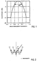
- Fig. 1 shows the directivity in the horizontal plane of antenna elements used in the simulation.
- the abscissa indicates the angle as normalized in terms of beam width B w while the ordinate indicates the relative gain as normalized by the peak power.
- the peak gain is chosen so that the power radiated from the antenna remains constant if the beam width B w is changed, and the side lobe level is chosen to be 15 dB below the peak power.
- Fig. 3 illustrates an example of a result of calculation.
- This Figure illustrates the error rate characteristic depending on the location of the mobile station, the abscissa representing the angle of the mobile station as viewed from the base station antenna (with the frontal direction of the array antenna being 0°) while the ordinate represents the error rate. Because the transmitting power of the mobile station is controlled, the dependency on the location of the mobile station does not depend on the distance between the mobile station and the base station, thus requiring a consideration of only the angular dependency.
- Respective curves shown illustrate the characteristics when the beam width B w of the antenna element 11 is changed in increment of 30° from 30° to 180°, all the curves been shown for four-element array antennas.
- the sector angle will be about 40° when the beam width B w is equal to 30°, and in a range of beam width B w of 60° ⁇ 180°, the sector angle is substantially equal to 90° and remains constant, indicating a result that there is no proportionality between the element beam width and the sector angle.
- An adaptive array antenna exhibits an excellent performance that it forms a null beam toward an interfering station (wave) and directs its beam peak toward a desired station (wave), but when a directional antenna element is used, the beam tracking capability is degraded when the direction of the mobile station (or the direction of the desired wave) shifts toward the end of the beam width. This is attributable to the fact that the directivity of the antenna element 11 has its gain inherently reduced toward the beam end. It then follows that the beam width of the antenna element can be increased in order to increase the sector angle. However, since the interference waves are oncoming from all directions in the CDMA system, as the beam width of the antenna element is increased, this result in receiving much more interference waves to degrade the reception SIR, also degrading the error rate characteristic. For these reasons, there results a consequence that the sector angle can not be increased if the beam width of the antenna element is increased.
- Fig. 4 illustrates the error rate characteristic depending on the location of the mobile station in the similar manner as in Fig. 3, but in this instance, curves 4a, 4b and 4c show the characteristics when the number of antenna elements which constitute the array (hereafter referred to as the number of array elements) is chosen to be equal to 4, 6 and 8, respectively.
- the beam width of the antenna element is equal to 120°. It will be seen from this Figure that as the number of array elements is increased, the sector angle can be increased if the elements having the same beam width are employed. When the number of elements which constitute an are employed.
- the number of elements which constitute an adaptive array antenna is equal to N
- the number of null beams which are formed in the directions of interference waves will be equal to N-1 (this is referred to as the freedom of the array antenna). Consequently, as the number of array elements increases, the number of null beams formed increases, thus improving the reception SIR and increasing the sector angle.
- a condition is employed that the number of interference waves is greater than the number of array elements, and accordingly, as the number of array elements is increased, the reception SIR is improved in a proportional manner, which is interpreted as increasing the sector angle.
- Fig. 5 A summary of these considerations is graphically shown in Fig. 5 where the abscissa represents the element beam width while the ordinate represents an angle (sector angle) within which the error rate is equal to or less than 10 -3 , with individual curves 5a, 5b and 5c representing characteristics when the number of array elements is changed to 4, 6 and 8, respectively.
- a rectilinear line 13 represents a line where a coincidence is reached between element beam width and the sector angle. For example, it will be seen that the number of array elements required when the element beam width is 90° and the sector angle is 90° is equal to 4 while the number of array elements when the element beam width is 120° and the sector angle is 120° is substantially equal to 6.
- the number of array elements required to achieve the sector angle of the same value 120° is substantially equal to 6, and when the number of array element is increased above this value, for example, to 8, the sector angle will be substantially equal to 135° or becomes greater than the element beam width of 120°. Conversely, when the number of array elements is reduced from 6 to 4, the sector angle will be substantially equal to 85°, which is less than the element beam width of 120°.
- Figs. 6 and 7 are schematic views showing a sector arrangement in which a single cell is divided into three 120°-sectors (sector #S1, #S2, #S3), with a base station antenna unit which incorporates an adaptive array antenna being disposed in each sector.
- Fig. 7 shows the arrangement of a base station antenna unit for three sectors.
- Antenna units BA1, BA2 and BA3 for the respective sectors each comprise an 8-element array antenna formed by 8 antenna elements AE 1 ⁇ AE 8 disposed in an array as spaced from a reflecting plate 21.
- Each of the antenna elements AE 1 ⁇ AE 8 is a directional antenna.
- the antenna element has a beam width within the horizontal plane equal to 90° which is narrower than the sector angle. Such beam width can be set up as desired by adjusting the spacing between the antenna elements AE 1 ⁇ AE 8 and the reflecting plate 21.
- the arrangement of Fig. 7 corresponds to the region #1 shown in.
- Fig. 8 shows the arrangement of an array antenna where half wavelengths dipoles associated with a reflecting plate are used as antenna elements.
- Each of antenna units BA1, BA2 and BA3 for the respective sectors comprises a reflecting metal plate 21, and dipole antennas DA 1 ⁇ DA 8 disposed in front of the reflecting plate 21.
- the distance between the surface of the reflecting plate 21 and the dipole antennas DA 1 ⁇ DA 8 is one-quarter the wavelength ⁇ used, for example.
- the beam width in the horizontal plane of each antenna element is equal to about 120°. If the distance between the dipole antenna elements and the surface of the reflecting plane 21 is reduced, the beam width will be reduced. Conversely, if the spacing is increased, the beam width will increase.
- Fig. 9 shows the arrangement of an array antenna in which patch antennas (micro-strip antennas) are used as antenna elements.
- the antenna comprises a dielectric substrate 22 with a metal sheet applied to its back surface, and quadrilateral metal patch antennas PA 1 ⁇ PA 8 disposed on the front surface of the substrate as spaced from each other.
- the beam width in the horizontal plane will be about 90°.
- horn antennas may be used as antenna elements, and a desired beam width can be obtained by choosing an opening angle of the horn antenna.
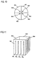
- Figs 10 and 11 show a second embodiment of the invention.
- Fig. 10 is a schematic view showing the sector arrangement where a single cell is divided into four 90°-sectors (sector #S1, #S2, #S3 and #S4), with a base station antenna unit incorporating an adaptive array antenna being disposed in each sector.
- Fig. 11 shows the arrangement of a base station antenna unit.
- An antenna unit for one sector is a 4-element array antenna formed by four antenna elements AE 1 ⁇ AE 4 , with each antenna element being a directional antenna.
- the antenna element has a beam width equal to 120° which is greater than the sector angle. This arrangement corresponds to the region #2 shown in Fig. 5.
- the antenna elements may be dipole antennas in the similar manner as shown in Fig. 8 or patch antennas in the similar manner as shown in Fig. 9.
- each of antenna elements which constitute an adaptive array antenna is narrower than a sector angle
- a broader service area can be achieved by increasing the number of array elements.
- antenna elements each having a beam width broader than a sector angle is used as the element antennas
- the number of array elements can be reduced than the number of elements which would be required when using antenna elements each having the element beam width equal to the sector angle.
Landscapes
- Engineering & Computer Science (AREA)
- Computer Networks & Wireless Communication (AREA)
- Variable-Direction Aerials And Aerial Arrays (AREA)
- Mobile Radio Communication Systems (AREA)
Applications Claiming Priority (3)
| Application Number | Priority Date | Filing Date | Title |
|---|---|---|---|
| JP14422197 | 1997-06-02 | ||
| JP14422197A JP3332329B2 (ja) | 1997-06-02 | 1997-06-02 | アダプティブアレーアンテナ装置 |
| PCT/JP1998/002408 WO1998056069A1 (fr) | 1997-06-02 | 1998-06-01 | Antenne reseau adaptable |
Publications (2)
| Publication Number | Publication Date |
|---|---|
| EP0923155A1 true EP0923155A1 (de) | 1999-06-16 |
| EP0923155A4 EP0923155A4 (de) | 2000-03-22 |
Family
ID=15357069
Family Applications (1)
| Application Number | Title | Priority Date | Filing Date |
|---|---|---|---|
| EP98923064A Withdrawn EP0923155A4 (de) | 1997-06-02 | 1998-06-01 | Adaptive gruppenantenne |
Country Status (6)
| Country | Link |
|---|---|
| EP (1) | EP0923155A4 (de) |
| JP (1) | JP3332329B2 (de) |
| KR (1) | KR100306466B1 (de) |
| CN (1) | CN1147025C (de) |
| CA (1) | CA2247349C (de) |
| WO (1) | WO1998056069A1 (de) |
Cited By (2)
| Publication number | Priority date | Publication date | Assignee | Title |
|---|---|---|---|---|
| EP1598900A4 (de) * | 2002-12-02 | 2008-05-21 | Airgain Inc | Antennenvorrichtung mit lenkbarem strahl und planare richtantenne |
| CN104716979A (zh) * | 2013-12-12 | 2015-06-17 | 启碁科技股份有限公司 | 无线电子装置及无线传输方法 |
Families Citing this family (6)
| Publication number | Priority date | Publication date | Assignee | Title |
|---|---|---|---|---|
| KR100452536B1 (ko) * | 2000-10-02 | 2004-10-12 | 가부시키가이샤 엔.티.티.도코모 | 이동통신기지국 장치 |
| KR20020041699A (ko) * | 2000-11-28 | 2002-06-03 | 이노영 | 셀룰라용 마이크로 스트립 패치 어레이 안테나 |
| CN100463376C (zh) * | 2002-12-20 | 2009-02-18 | 中兴通讯股份有限公司 | 全自适应智能天线接收装置 |
| JP4241440B2 (ja) * | 2004-03-03 | 2009-03-18 | 株式会社日立製作所 | パケットスケジュール方法及び無線通信装置 |
| US10651568B2 (en) * | 2016-07-19 | 2020-05-12 | Quintel Cayman Limited | Base station antenna system with enhanced array spacing |
| US10236966B2 (en) * | 2017-01-06 | 2019-03-19 | Skyworks Solutions, Inc. | Beamforming of harmonics |
Family Cites Families (7)
| Publication number | Priority date | Publication date | Assignee | Title |
|---|---|---|---|---|
| US3273144A (en) * | 1963-04-02 | 1966-09-13 | Fishbein William | Narrow beam antenna system |
| US3903524A (en) * | 1973-05-25 | 1975-09-02 | Hazeltine Corp | Antenna system using variable phase pattern synthesis |
| US5548813A (en) * | 1994-03-24 | 1996-08-20 | Ericsson Inc. | Phased array cellular base station and associated methods for enhanced power efficiency |
| JP3540374B2 (ja) * | 1994-07-20 | 2004-07-07 | Kddi株式会社 | 移動通信系の基地局用アンテナ装置 |
| US6006069A (en) * | 1994-11-28 | 1999-12-21 | Bosch Telecom Gmbh | Point-to-multipoint communications system |
| JPH0927714A (ja) * | 1995-07-11 | 1997-01-28 | N T T Ido Tsushinmo Kk | マルチビームアンテナ装置 |
| JPH10174160A (ja) * | 1996-12-13 | 1998-06-26 | N T T Ido Tsushinmo Kk | アレーアンテナ |
-
1997
- 1997-06-02 JP JP14422197A patent/JP3332329B2/ja not_active Expired - Fee Related
-
1998
- 1998-06-01 WO PCT/JP1998/002408 patent/WO1998056069A1/ja not_active Ceased
- 1998-06-01 KR KR1019980706811A patent/KR100306466B1/ko not_active Expired - Fee Related
- 1998-06-01 CA CA 2247349 patent/CA2247349C/en not_active Expired - Fee Related
- 1998-06-01 EP EP98923064A patent/EP0923155A4/de not_active Withdrawn
- 1998-06-01 CN CNB988000490A patent/CN1147025C/zh not_active Expired - Fee Related
Cited By (4)
| Publication number | Priority date | Publication date | Assignee | Title |
|---|---|---|---|---|
| EP1598900A4 (de) * | 2002-12-02 | 2008-05-21 | Airgain Inc | Antennenvorrichtung mit lenkbarem strahl und planare richtantenne |
| US7570215B2 (en) | 2002-12-02 | 2009-08-04 | Airgain, Inc. | Antenna device with a controlled directional pattern and a planar directional antenna |
| CN104716979A (zh) * | 2013-12-12 | 2015-06-17 | 启碁科技股份有限公司 | 无线电子装置及无线传输方法 |
| CN104716979B (zh) * | 2013-12-12 | 2017-11-21 | 启碁科技股份有限公司 | 无线电子装置及无线传输方法 |
Also Published As
| Publication number | Publication date |
|---|---|
| JPH10335918A (ja) | 1998-12-18 |
| CA2247349C (en) | 2002-04-09 |
| JP3332329B2 (ja) | 2002-10-07 |
| CA2247349A1 (en) | 1998-12-10 |
| CN1147025C (zh) | 2004-04-21 |
| KR100306466B1 (ko) | 2001-11-02 |
| WO1998056069A1 (fr) | 1998-12-10 |
| KR20000064538A (ko) | 2000-11-06 |
| EP0923155A4 (de) | 2000-03-22 |
| CN1217827A (zh) | 1999-05-26 |
Similar Documents
| Publication | Publication Date | Title |
|---|---|---|
| CA2511684C (en) | Null-fill antenna, omni antenna, and radio communication equipment | |
| KR100767249B1 (ko) | 무선 애플리케이션용 고이득 안테나 | |
| US20120115548A1 (en) | Mobile communication base station antenna and mobile communication base station antenna system | |
| US20080062058A1 (en) | Multiple antenna array with high isolation | |
| JPH10294614A (ja) | セルラー・アンテナ | |
| US6512934B2 (en) | Adaptive array antenna | |
| Lindmark et al. | Dual-polarized array for signal-processing applications in wireless communications | |
| CA2247349C (en) | Adaptive array antenna unit | |
| US20240275075A1 (en) | Advanced antenna systems with reduced sidelobes | |
| Kijima et al. | Development of a dual-frequency base station antenna for cellular mobile radios | |
| EP1444752B1 (de) | Adaptives antennenarray für den zellularfunk | |
| EP3985794A1 (de) | Strahlungselement und basisstationsantenne | |
| JP2981087B2 (ja) | ビームアンテナ | |
| KR20200059492A (ko) | 격리도가 향상된 고이득 광대역 패치 배열 안테나 | |
| Nakano et al. | Small-sized shaped beam base station antenna with superior intersector interference reduction in high speed cellular systems | |
| Al Ka’bi | Steered Beam Adaptive Antenna Arrays | |
| Gans et al. | Co-channel interference in high capacity fixed wireless loops (FWL) | |
| JP2001085922A (ja) | アンテナ装置 | |
| Sumi et al. | Azimuth pattern design to reduce interference in overlapping sectors using combined tilt | |
| HK1087536A (en) | Null-fill antenna, omni antenna, and radio communication equipment |
Legal Events
| Date | Code | Title | Description |
|---|---|---|---|
| PUAI | Public reference made under article 153(3) epc to a published international application that has entered the european phase |
Free format text: ORIGINAL CODE: 0009012 |
|
| 17P | Request for examination filed |
Effective date: 19980825 |
|
| AK | Designated contracting states |
Kind code of ref document: A1 Designated state(s): DE FR GB IT SE |
|
| A4 | Supplementary search report drawn up and despatched |
Effective date: 20000207 |
|
| AK | Designated contracting states |
Kind code of ref document: A4 Designated state(s): DE FR GB IT SE |
|
| RIC1 | Information provided on ipc code assigned before grant |
Free format text: 7H 01Q 3/26 A, 7H 01Q 21/06 B, 7H 04B 7/26 B, 7H 01Q 21/08 B, 7H 01Q 21/29 B, 7H 04Q 7/36 B, 7H 01Q 1/24 B |
|
| 17Q | First examination report despatched |
Effective date: 20050329 |
|
| STAA | Information on the status of an ep patent application or granted ep patent |
Free format text: STATUS: THE APPLICATION IS DEEMED TO BE WITHDRAWN |
|
| 18D | Application deemed to be withdrawn |
Effective date: 20150106 |