EP0923183A2 - Source d'énergie et véhicule électrique muni de celle-ci - Google Patents
Source d'énergie et véhicule électrique muni de celle-ci Download PDFInfo
- Publication number
- EP0923183A2 EP0923183A2 EP98120421A EP98120421A EP0923183A2 EP 0923183 A2 EP0923183 A2 EP 0923183A2 EP 98120421 A EP98120421 A EP 98120421A EP 98120421 A EP98120421 A EP 98120421A EP 0923183 A2 EP0923183 A2 EP 0923183A2
- Authority
- EP
- European Patent Office
- Prior art keywords
- power source
- circuit
- current control
- unit
- source unit
- Prior art date
- Legal status (The legal status is an assumption and is not a legal conclusion. Google has not performed a legal analysis and makes no representation as to the accuracy of the status listed.)
- Withdrawn
Links
Images


Classifications
-
- H—ELECTRICITY
- H02—GENERATION; CONVERSION OR DISTRIBUTION OF ELECTRIC POWER
- H02J—ELECTRIC POWER NETWORKS; CIRCUIT ARRANGEMENTS OR SYSTEMS FOR SUPPLYING OR DISTRIBUTING ELECTRIC POWER; SYSTEMS FOR STORING ELECTRIC ENERGY
- H02J7/00—Circuit arrangements for charging or discharging batteries or for supplying loads from batteries
- H02J7/34—Parallel operation in networks using both storage and other DC sources, e.g. providing buffering
- H02J7/345—Parallel operation in networks using both storage and other DC sources, e.g. providing buffering using capacitors as storage or buffering devices
Definitions
- the present invention relates to a power source unit for effectively transferring energy between the first and the second power sources and an electric vehicle loaded therewith, and more particularly, to a power source unit comprising first and second power sources and an insulation type power transfer circuit such as a current control circuit, etc.
- a power source unit for conventional electric vehicles is generally designed to meet the above mentioned radical, rapid and frequent change in motor load even though the capacity and the duration of life of cells are sacrificed to a certain extent. On the other hand, it is also tried to develop a power source unit for electric vehicles sufficient to increase the capacity and the duration of life of cells.
- a change in a loading condition of a cell as a main power source has been conventionally controlled to keep constant to the utmost by means of a power source unit which comprises a combination of the main power source and a cell or condenser of high capacity as a sub power source, thereby charging the above mentioned radical, rapid and frequent change in the motor load to the sub power source.
- Fig. 4 shows a conventional power source unit for electric vehicles.
- the power source unit 5 comprises a main power source 51 including a cell and a sub power source 52 including a cell or condenser.
- the main power source 51 and a sub power source 52 are connected in parallel (in Fig. 4, a condenser is used as the sub power source for convenience).
- Energy is supplied from the power source unit 5 to a motor unit 6 comprising an inverter 61 and a vehicle driving motor 62.
- a terminal voltage of the main and sub power sources 51 and 52 is the same.
- a partial current charge ratio is spontaneously determined by an inverse ratio of respective internal resistance (R1 and R2), it is limited to control the change in the loading condition of the main power source within a certain level of range.
- a power source unit 5 comprises a current control circuit 53 consisting of a DC/DC converter which is connected between a main power source 51 and a sub power source 52, as shown in Fig. 5.
- a current division ratio of the main power source 51 and the sub power source 52 is determined by a current control circuit 53, thereby the loading condition of the main power source 51 being limited within a certain region.
- a cell is used as the main power source 51 in the power source unit, while a fuel cell or an engine generator is employed as the main source in the case of a so-called hybrid electric vehicle.
- the main power source is, for example, an engine generator
- a current control circuit 73 is arranged between a main power source (i.e., engine generator) 71 and a sub power source (in this example, shown as a cell) 72.
- a main power source i.e., engine generator
- a sub power source in this example, shown as a cell
- the efficiency of energy transfer in the current control circuit 73 directly affects the overall efficiency of the power source unit because all energies pass through the current control circuit 73.
- the present invention has been made based on the recognition of that, in a power source unit comprising first and second power sources and an insulation type power transfer circuit having two input terminals and two output terminals, when energy is transferred from the first power source to the second power source, if it is possible to transfer only a part of energy through an insulated type power transfer circuit, energy loss in the power transfer circuit can be reduced.
- a power source unit comprises a first power source, an insulated type power transfer circuit having two input terminals and two output terminals, and a parallel circuit including a second power source and a load unit.
- the first power source is connected between the two input terminals of the insulated type power transfer circuit.
- One of terminals of the first power source is connected to the first output terminal of the insulated type power transfer circuit.
- the parallel circuit is connected between the second output terminal of the insulated type power transfer circuit and the second terminal of the first power source. In this power source unit, energy transfer is performed between the first power source and the parallel circuit.
- the first power source may be an generator (generally, DC generator) or a fuel cell, or a galvanic cell (hereinafter simply referred to as a cell), while the second power source may be a condenser or a cell.
- the insulation type power transfer circuit is a power circuit generally called as a DC/DC converter in which input and output sides thereof are insulated and output voltage or current is controlled.
- a DC/DC converter is employed as the insulation type power transfer circuit.
- an electric vehicle according to the present invention is loaded with the above mentioned power source unit, the load unit comprising a motor to be used to drive the vehicle.
- the term "electric vehicle” used herein is not limited to vehicles or auto trucks but includes motorcycles, mopeds and the like.
- the above mentioned power source unit is not limited only to an application to the electric vehicle but is applicable to ships, track vehicles and the like which require relatively high power.
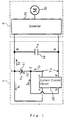
- the power source unit 1 comprises a cell as a main power source 11 (first power source), a condenser as a sub power source (second power source) and an insulation type DC/DC converter as a current control circuit 13 (insulation type power transfer circuit) provided with two input terminals and two output terminals.
- Input terminals a and b of the current control circuit 13 are connected to a (+) terminal e and a (-) terminal f of the main power source 11, respectively.
- output terminals c and d of the current control circuit 13 are connected to the (-) terminal f of the main power source 11 and one terminal h of the sub power source 12, respectively.
- the other terminal g of the sub power source 12 is connected to the (+) terminal e of the main power source 11. Further, a motor unit 2 (load unit) comprising an inverter 21 and a vehicle driving motor 22 is connected to terminals g and h of the sub power source 2.
- Va Vb + Vd
- Vb the voltage of the main power source 11 (i.e., the input voltage of the current control circuit 13)
- Vd the output voltage of the circuit 13.
- the input power Pi of the current control circuit 13 is given as the following equation.
- the current flowing from the main power source 11 to the sub power source 12 is equal to the output current Id of the current control circuit 13, while the voltage Va between the terminals g and h of the sub power source 12 is equal to a sum of the input voltage Vb and the input voltage Vd of the current control circuit 13 as shown in the equation (1). Accordingly, the main power source 11 and the current control circuit 13 transfer energy to the sub power source while taking partial charge of the voltage Vb and Vd each other in the power source unit 1 shown in Fig. 1.
- a DC/DC converting efficiency ⁇ ' of the current control circuit 53 represents an efficiency H' of the power source unit itself, if an energy loss by the internal resistance in the main and sub power sources 51 and 52 is ignored.
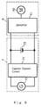
- the (+) terminal e of the main power source 11 is connected to one of terminals of the condenser as the sub power source 12 and the (-) terminal f thereof is connected to the output terminal c of the current control circuit 13 as shown in Fig. 1, while a similar effect can be easily obtained when the (-) terminal f of the main power source 11 is connected to one of the terminals of the condenser as the sub power source 12 and the (+) terminal e of the main power source 11 is connected to the output terminal d of the current control circuit 13 as shown in Fig. 2.
- the power source unit which comprises one current control circuit in the above mentioned embodiment, it is possible to provide a number of variations of the present power source unit having structure in which the main power source 11 supplies energy to a parallel connecting circuit of the condenser as the sub power source 12 and the electric power unit 2 through a terminal which is not connected to the output terminal of the current control circuit.
- the power source unit may comprise a plurality of current control circuits as shown in Fig. 3 (A) to (D).
- a power source unit 1A shown in Fig. 3(A) two terminals of a main power source 111 are connected to each of two input terminals of plural (in this embodiment, two) current control circuits 131a and 131b. Further, one of output terminals of the current control circuit 131a is connected to one of the terminals of the main power source 111 and the other output terminal thereof is connected to one of output terminals of the current control circuit 131b.
- a parallel connecting circuit of a sub power source 12 and an electric power unit 2 is connected between the other terminal of the main power source 111 and the other output terminal of the current control circuit 131b.
- a power source unit 1B as shown in Fig. 3 (B) comprises serially connected plural sets (for convenience sake, two sets) of the current control circuit 13 and the main power source 11 shown in Fig. 1. Namely, in Fig. 3 (B), one set of a current control circuit 132a and a main power source 112a and the other set of a current control circuit 132b and a main power source 112b are serially connected, to both ends of which a parallel connecting circuit of the sub power source 12 and the electric power unit 2 is connected.
- a power source unit 1C as shown in Fig. 3 (C) comprises serially connected plural sets of the current control circuit 13 and the main power source 11 shown in Fig. 1 and similar sets of the circuit 13 and the source 11 shown in Fig. 2.
- the power source unit comprises one set of a current control circuit 132a and a main power source 113a and the other set of a current control circuit 133b and a main power source 113b are connected, output terminals of each circuit control circuit 133a and 133b being connected each other on the side where each main power source is not connected.
- a parallel connecting circuit of the sub power source 12 and the electric power unit 2 is connected between each terminal of the main power sources 113a and 113b on the side to which each output terminal of the current control circuits 133a and 133b is not connected.
- a power source unit 1D as shown in Fig. 3 (D) comprises connected two sets of the current control circuit 13 and the main power source 11 shown in Fig. 1.
- one set of current control circuit 134a and a main power source 114a and the other set of a current control circuit 134b and a main power source 114b are serially connected, an output terminal of the current control circuit 134a on the side to which the main power source 114a being connected to an output terminal of the current control circuit 134b on the side to which the main power source 114b is not connected, while an output terminal of the current control circuit 134a on the side to which the main power source 114a is not connected being connected to an output terminal of the current control circuit 134b on the side to which the main power source 114b is connected.
- a parallel connecting circuit of the sub power source 12 and the electric power unit 2 is connected between each terminal of the main power sources 114a and 114b on each side to which each output terminal of the current control circuits 134a and
Landscapes
- Engineering & Computer Science (AREA)
- Power Engineering (AREA)
- Electric Propulsion And Braking For Vehicles (AREA)
- Dc-Dc Converters (AREA)
- Direct Current Feeding And Distribution (AREA)
- Charge And Discharge Circuits For Batteries Or The Like (AREA)
- Arrangement Or Mounting Of Propulsion Units For Vehicles (AREA)
Applications Claiming Priority (2)
| Application Number | Priority Date | Filing Date | Title |
|---|---|---|---|
| JP32386397 | 1997-11-10 | ||
| JP32386397A JP3713521B2 (ja) | 1997-11-10 | 1997-11-10 | 電源装置およびこれが搭載される電気自動車 |
Publications (2)
| Publication Number | Publication Date |
|---|---|
| EP0923183A2 true EP0923183A2 (fr) | 1999-06-16 |
| EP0923183A3 EP0923183A3 (fr) | 2000-09-20 |
Family
ID=18159438
Family Applications (1)
| Application Number | Title | Priority Date | Filing Date |
|---|---|---|---|
| EP98120421A Withdrawn EP0923183A3 (fr) | 1997-11-10 | 1998-10-28 | Source d'énergie et véhicule électrique muni de celle-ci |
Country Status (3)
| Country | Link |
|---|---|
| US (1) | US6265853B1 (fr) |
| EP (1) | EP0923183A3 (fr) |
| JP (1) | JP3713521B2 (fr) |
Cited By (4)
| Publication number | Priority date | Publication date | Assignee | Title |
|---|---|---|---|---|
| EP1390999A4 (fr) * | 2001-05-23 | 2004-09-01 | Relion Inc | Groupe d'alimentation par pile a combustible, procede de repartition d'energie et procede de fonctionnement d'un groupe d'alimentation par pile a combustible |
| EP1742320A2 (fr) * | 2005-07-08 | 2007-01-10 | Yamaha Hatsudoki Kabushiki Kaisha | Source d'alimentation en courant continu |
| EP2612688A1 (fr) * | 2012-01-09 | 2013-07-10 | Weinmann Geräte für Medizin GmbH & Co. KG | Procédé et dispositif dýassistance respiratoire |
| DE102016200769A1 (de) * | 2016-01-21 | 2017-07-27 | Bayerische Motoren Werke Aktiengesellschaft | Verbesserte Stromquellenanordnung mit mehreren Stromquellen |
Families Citing this family (10)
| Publication number | Priority date | Publication date | Assignee | Title |
|---|---|---|---|---|
| JP4604389B2 (ja) * | 2001-05-09 | 2011-01-05 | 株式会社デンソー | 燃料電池システム |
| JP3874344B2 (ja) | 2002-01-17 | 2007-01-31 | 株式会社小松製作所 | ハイブリッド電源システム |
| US7614381B2 (en) * | 2003-03-28 | 2009-11-10 | Caterpillar Inc. | Power system with an integrated lubrication circuit |
| JP4476021B2 (ja) * | 2004-05-24 | 2010-06-09 | 株式会社日立製作所 | ディスクアレイシステム |
| CN101361254B (zh) | 2005-11-24 | 2012-05-30 | 株式会社小松制作所 | Ac连接双方向dc—dc转换器、使用了该转换器的混合电源系统及混合动力车辆 |
| US20080061045A1 (en) * | 2006-09-11 | 2008-03-13 | The Esab Group, Inc. | Systems And Methods For Providing Paralleling Power Sources For Arc Cutting And Welding |
| WO2009149518A1 (fr) * | 2008-06-13 | 2009-12-17 | Ceramic Fuel Cells Limited | Système et procédé de stabilisation de pile à combustible |
| US8295950B1 (en) | 2008-07-02 | 2012-10-23 | Jerry Lee Wordsworth | Intelligent power management system |
| CN102324765A (zh) * | 2011-09-05 | 2012-01-18 | 徐忠方 | 车载笔记本电脑、数码设备用充电器 |
| DE102017219713A1 (de) | 2017-11-07 | 2019-05-09 | Bayerische Motoren Werke Aktiengesellschaft | Halbbrückenmodul für einen stromwandler |
Citations (3)
| Publication number | Priority date | Publication date | Assignee | Title |
|---|---|---|---|---|
| JPH03277165A (ja) * | 1990-03-27 | 1991-12-09 | Shinko Electric Co Ltd | バッテリー電源式車両車 |
| JPH05219727A (ja) * | 1992-02-06 | 1993-08-27 | Fuji Electric Co Ltd | 直流昇圧装置 |
| US5446365A (en) * | 1992-05-19 | 1995-08-29 | Kabushiki Kaisha Toshiba | Method and apparatus for controlling a battery car |
Family Cites Families (8)
| Publication number | Priority date | Publication date | Assignee | Title |
|---|---|---|---|---|
| JPS6056948B2 (ja) * | 1977-02-08 | 1985-12-12 | 株式会社日本自動車部品総合研究所 | 電磁弁駆動装置 |
| JPS55136870A (en) * | 1979-04-10 | 1980-10-25 | Toshiba Corp | Voltage conversion type power supply |
| FR2633115B1 (fr) * | 1988-06-17 | 1993-02-12 | Gen Electric Cgr | Alimentation stabilisee a taux d'ondulation reduit |
| DE4042377C2 (de) * | 1990-04-27 | 1996-11-14 | Baumueller Nuernberg Gmbh | Elektrische Antriebseinrichtung für ein Fahrzeug |
| US5486749A (en) * | 1993-06-21 | 1996-01-23 | Ast Research, Inc. | Multiple battery charger with a power source control |
| US5563479A (en) * | 1993-10-29 | 1996-10-08 | Aisin Seiki Kabushiki Kaisha | Power supply apparatus for electric vehicle |
| JP3477852B2 (ja) * | 1994-11-04 | 2003-12-10 | 株式会社デンソー | Igbt駆動回路および点火装置 |
| US5659463A (en) * | 1996-03-14 | 1997-08-19 | Hughes Electronics | High-efficiency summing power converter and method therefor |
-
1997
- 1997-11-10 JP JP32386397A patent/JP3713521B2/ja not_active Expired - Fee Related
-
1998
- 1998-10-28 EP EP98120421A patent/EP0923183A3/fr not_active Withdrawn
- 1998-11-05 US US09/186,072 patent/US6265853B1/en not_active Expired - Fee Related
Patent Citations (3)
| Publication number | Priority date | Publication date | Assignee | Title |
|---|---|---|---|---|
| JPH03277165A (ja) * | 1990-03-27 | 1991-12-09 | Shinko Electric Co Ltd | バッテリー電源式車両車 |
| JPH05219727A (ja) * | 1992-02-06 | 1993-08-27 | Fuji Electric Co Ltd | 直流昇圧装置 |
| US5446365A (en) * | 1992-05-19 | 1995-08-29 | Kabushiki Kaisha Toshiba | Method and apparatus for controlling a battery car |
Cited By (6)
| Publication number | Priority date | Publication date | Assignee | Title |
|---|---|---|---|---|
| EP1390999A4 (fr) * | 2001-05-23 | 2004-09-01 | Relion Inc | Groupe d'alimentation par pile a combustible, procede de repartition d'energie et procede de fonctionnement d'un groupe d'alimentation par pile a combustible |
| EP1742320A2 (fr) * | 2005-07-08 | 2007-01-10 | Yamaha Hatsudoki Kabushiki Kaisha | Source d'alimentation en courant continu |
| EP2612688A1 (fr) * | 2012-01-09 | 2013-07-10 | Weinmann Geräte für Medizin GmbH & Co. KG | Procédé et dispositif dýassistance respiratoire |
| DE102016200769A1 (de) * | 2016-01-21 | 2017-07-27 | Bayerische Motoren Werke Aktiengesellschaft | Verbesserte Stromquellenanordnung mit mehreren Stromquellen |
| US10618419B2 (en) | 2016-01-21 | 2020-04-14 | Bayerische Motoren Werke Aktiengesellschaft | Energy storage arrangement comprising multiple energy stores |
| DE102016200769B4 (de) | 2016-01-21 | 2024-08-22 | Bayerische Motoren Werke Aktiengesellschaft | Verbesserte Stromquellenanordnung mit mehreren Stromquellen |
Also Published As
| Publication number | Publication date |
|---|---|
| US6265853B1 (en) | 2001-07-24 |
| EP0923183A3 (fr) | 2000-09-20 |
| JPH11146566A (ja) | 1999-05-28 |
| JP3713521B2 (ja) | 2005-11-09 |
Similar Documents
| Publication | Publication Date | Title |
|---|---|---|
| EP0923183A2 (fr) | Source d'énergie et véhicule électrique muni de celle-ci | |
| US8381852B2 (en) | Multiple battery system of a motor vehicle | |
| US6737756B1 (en) | Power supply for an automotive vehicle using DC-to-DC converter for charge transfer | |
| EP2367258B1 (fr) | Chargeur de batterie combiné et égaliseur de batterie | |
| US20040112320A1 (en) | Motor vehicle electric system | |
| US20120007557A1 (en) | Motive Power Dual Battery Pack | |
| US20080218104A1 (en) | Power management for multi-module energy storage systems in electric, hybrid electric, and fuel cell vehicles | |
| KR20030094002A (ko) | 하이브리드형 전원 시스템 | |
| Khan et al. | Bi-directional power management and fault tolerant feature in a 5-kW multilevel dc–dc converter with modular architecture | |
| CN102782980A (zh) | 电源系统及电动汽车 | |
| KR20160113228A (ko) | 차량 전기 시스템 | |
| US20200403197A1 (en) | Battery module with stacked cells having offset tabs | |
| EP4506201A1 (fr) | Module de batterie de véhicule comprenant un dispositif de conversion de puissance et système de batterie de véhicule formé sur la base de modules de batterie de véhicule | |
| US5986431A (en) | Battery power system for vehicles | |
| JP2004056995A (ja) | ハイブリッド電源システム | |
| JP3293683B2 (ja) | 直流電源装置 | |
| Khan et al. | 5 kW multilevel DC-DC converter for hybrid electric and fuel cell automotive applications | |
| EP4367774A1 (fr) | Systèmes électriques bidirectionnels avec blocs-batteries polyvalents à haute tension | |
| JP2023514154A (ja) | バッテリ装置および電圧供給方法 | |
| JP3558546B2 (ja) | 電気自動車の電源システム | |
| CN110165749A (zh) | 电动汽车、车载充电机电路、电池电路和充放电控制方法 | |
| JP4329454B2 (ja) | 電気自動車システム | |
| US7402967B2 (en) | DC power source | |
| JP3558159B2 (ja) | 電気自動車の電源システム | |
| US20260125010A1 (en) | Electrical power supply system for a vehicle |
Legal Events
| Date | Code | Title | Description |
|---|---|---|---|
| PUAI | Public reference made under article 153(3) epc to a published international application that has entered the european phase |
Free format text: ORIGINAL CODE: 0009012 |
|
| AK | Designated contracting states |
Kind code of ref document: A2 Designated state(s): DE FR GB IT |
|
| AX | Request for extension of the european patent |
Free format text: AL;LT;LV;MK;RO;SI |
|
| PUAL | Search report despatched |
Free format text: ORIGINAL CODE: 0009013 |
|
| AK | Designated contracting states |
Kind code of ref document: A3 Designated state(s): AT BE CH CY DE DK ES FI FR GB GR IE IT LI LU MC NL PT SE |
|
| AX | Request for extension of the european patent |
Free format text: AL;LT;LV;MK;RO;SI |
|
| RIC1 | Information provided on ipc code assigned before grant |
Free format text: 7H 02J 7/02 A, 7H 02J 7/34 B |
|
| AKX | Designation fees paid |
Free format text: DE FR GB IT |
|
| 17P | Request for examination filed |
Effective date: 20010320 |
|
| 17Q | First examination report despatched |
Effective date: 20071008 |
|
| STAA | Information on the status of an ep patent application or granted ep patent |
Free format text: STATUS: THE APPLICATION IS DEEMED TO BE WITHDRAWN |
|
| 18D | Application deemed to be withdrawn |
Effective date: 20080219 |