EP0923185A1 - Dispositif d'interruption electrique comportant un module de communication - Google Patents
Dispositif d'interruption electrique comportant un module de communication Download PDFInfo
- Publication number
- EP0923185A1 EP0923185A1 EP98410116A EP98410116A EP0923185A1 EP 0923185 A1 EP0923185 A1 EP 0923185A1 EP 98410116 A EP98410116 A EP 98410116A EP 98410116 A EP98410116 A EP 98410116A EP 0923185 A1 EP0923185 A1 EP 0923185A1
- Authority
- EP
- European Patent Office
- Prior art keywords
- module
- bus
- remote control
- auxiliary contacts
- communication
- Prior art date
- Legal status (The legal status is an assumption and is not a legal conclusion. Google has not performed a legal analysis and makes no representation as to the accuracy of the status listed.)
- Granted
Links
- 238000004891 communication Methods 0.000 title claims abstract description 33
- 230000011664 signaling Effects 0.000 claims description 11
- 230000004044 response Effects 0.000 claims description 2
- 230000005540 biological transmission Effects 0.000 description 2
- 230000006870 function Effects 0.000 description 2
- 241001415961 Gaviidae Species 0.000 description 1
- 238000010586 diagram Methods 0.000 description 1
- 230000007246 mechanism Effects 0.000 description 1
- 238000000034 method Methods 0.000 description 1
- 208000016802 peripheral primitive neuroectodermal tumor Diseases 0.000 description 1
- 230000008569 process Effects 0.000 description 1
- 239000013589 supplement Substances 0.000 description 1
Images


Classifications
-
- H—ELECTRICITY
- H04—ELECTRIC COMMUNICATION TECHNIQUE
- H04L—TRANSMISSION OF DIGITAL INFORMATION, e.g. TELEGRAPHIC COMMUNICATION
- H04L12/00—Data switching networks
- H04L12/02—Details
- H04L12/12—Arrangements for remote connection or disconnection of substations or of equipment thereof
-
- H—ELECTRICITY
- H01—ELECTRIC ELEMENTS
- H01H—ELECTRIC SWITCHES; RELAYS; SELECTORS; EMERGENCY PROTECTIVE DEVICES
- H01H71/00—Details of the protective switches or relays covered by groups H01H73/00 - H01H83/00
- H01H71/10—Operating or release mechanisms
- H01H71/12—Automatic release mechanisms with or without manual release
- H01H71/46—Automatic release mechanisms with or without manual release having means for operating auxiliary contacts additional to the main contacts
-
- H—ELECTRICITY
- H01—ELECTRIC ELEMENTS
- H01H—ELECTRIC SWITCHES; RELAYS; SELECTORS; EMERGENCY PROTECTIVE DEVICES
- H01H2300/00—Orthogonal indexing scheme relating to electric switches, relays, selectors or emergency protective devices covered by H01H
- H01H2300/03—Application domotique, e.g. for house automation, bus connected switches, sensors, loads or intelligent wiring
-
- H—ELECTRICITY
- H01—ELECTRIC ELEMENTS
- H01H—ELECTRIC SWITCHES; RELAYS; SELECTORS; EMERGENCY PROTECTIVE DEVICES
- H01H71/00—Details of the protective switches or relays covered by groups H01H73/00 - H01H83/00
- H01H71/02—Housings; Casings; Bases; Mountings
- H01H71/0207—Mounting or assembling the different parts of the circuit breaker
- H01H71/0228—Mounting or assembling the different parts of the circuit breaker having provisions for interchangeable or replaceable parts
-
- H—ELECTRICITY
- H01—ELECTRIC ELEMENTS
- H01H—ELECTRIC SWITCHES; RELAYS; SELECTORS; EMERGENCY PROTECTIVE DEVICES
- H01H89/00—Combinations of two or more different basic types of electric switches, relays, selectors and emergency protective devices, not covered by any single one of the other main groups of this subclass
- H01H89/06—Combination of a manual reset circuit with a contactor, i.e. the same circuit controlled by both a protective and a remote control device
-
- Y—GENERAL TAGGING OF NEW TECHNOLOGICAL DEVELOPMENTS; GENERAL TAGGING OF CROSS-SECTIONAL TECHNOLOGIES SPANNING OVER SEVERAL SECTIONS OF THE IPC; TECHNICAL SUBJECTS COVERED BY FORMER USPC CROSS-REFERENCE ART COLLECTIONS [XRACs] AND DIGESTS
- Y02—TECHNOLOGIES OR APPLICATIONS FOR MITIGATION OR ADAPTATION AGAINST CLIMATE CHANGE
- Y02B—CLIMATE CHANGE MITIGATION TECHNOLOGIES RELATED TO BUILDINGS, e.g. HOUSING, HOUSE APPLIANCES OR RELATED END-USER APPLICATIONS
- Y02B90/00—Enabling technologies or technologies with a potential or indirect contribution to GHG emissions mitigation
- Y02B90/20—Smart grids as enabling technology in buildings sector
-
- Y—GENERAL TAGGING OF NEW TECHNOLOGICAL DEVELOPMENTS; GENERAL TAGGING OF CROSS-SECTIONAL TECHNOLOGIES SPANNING OVER SEVERAL SECTIONS OF THE IPC; TECHNICAL SUBJECTS COVERED BY FORMER USPC CROSS-REFERENCE ART COLLECTIONS [XRACs] AND DIGESTS
- Y02—TECHNOLOGIES OR APPLICATIONS FOR MITIGATION OR ADAPTATION AGAINST CLIMATE CHANGE
- Y02D—CLIMATE CHANGE MITIGATION TECHNOLOGIES IN INFORMATION AND COMMUNICATION TECHNOLOGIES [ICT], I.E. INFORMATION AND COMMUNICATION TECHNOLOGIES AIMING AT THE REDUCTION OF THEIR OWN ENERGY USE
- Y02D30/00—Reducing energy consumption in communication networks
- Y02D30/50—Reducing energy consumption in communication networks in wire-line communication networks, e.g. low power modes or reduced link rate
-
- Y—GENERAL TAGGING OF NEW TECHNOLOGICAL DEVELOPMENTS; GENERAL TAGGING OF CROSS-SECTIONAL TECHNOLOGIES SPANNING OVER SEVERAL SECTIONS OF THE IPC; TECHNICAL SUBJECTS COVERED BY FORMER USPC CROSS-REFERENCE ART COLLECTIONS [XRACs] AND DIGESTS
- Y04—INFORMATION OR COMMUNICATION TECHNOLOGIES HAVING AN IMPACT ON OTHER TECHNOLOGY AREAS
- Y04S—SYSTEMS INTEGRATING TECHNOLOGIES RELATED TO POWER NETWORK OPERATION, COMMUNICATION OR INFORMATION TECHNOLOGIES FOR IMPROVING THE ELECTRICAL POWER GENERATION, TRANSMISSION, DISTRIBUTION, MANAGEMENT OR USAGE, i.e. SMART GRIDS
- Y04S20/00—Management or operation of end-user stationary applications or the last stages of power distribution; Controlling, monitoring or operating thereof
- Y04S20/14—Protecting elements, switches, relays or circuit breakers
Definitions
- the invention relates to an electrical interruption device comprising a plurality locations for auxiliary contacts whose state is representative of the state of the device, at least one auxiliary contact arranged in one of said locations and a module for communication intended to be connected to a communication bus.
- FIG. 1 to 3 illustrate the various types of communication provided in the known circuit breakers.
- the circuit breaker 1, according to FIG. 1, comprises a trip unit 2 of the electronic type.
- the trigger 2 has a communication output allowing data transmission to an external signaling module 4 by a unidirectional serial link 3.
- trigger 2 can transmit data representative of the settings of the trigger, measured current values, exceeding certain thresholds, cause of a trigger.
- Module 4 can, for its part, be connected to a bus communication 5.
- a trigger of this type is, for example, marketed by the Applicant under the brand STR53UE, in association with a brand circuit breaker COMPACT NS, to communicate with a DIALPACT brand module likely to communicate with a supervisor through a BatiBUS or JBUS type bus.
- the circuit breaker 1 according to FIG. 2 also includes a trip unit 2 of the electronic type. This is capable of transmitting information to a bus 6 which can be connected directly to a supervisory unit. In addition, it can be fitted with an electric control 7 connected to a bus 5, via an external remote control module 8.
- a trigger of this type is, for example, marketed by the Applicant under the brand STR68, in association with a MASTERPACT brand circuit breaker. It transmits information representative of the state of the circuit breaker or the state of the network to a supervisor by via a bus of JBUS or PPNET type.
- the circuit breaker 1 of FIG. 3 is equipped with a trip unit 2 of the magnetothermal type.
- a such a trigger cannot communicate directly with an external bus.
- the circuit breaker 1 conventionally comprises a certain number of auxiliary contacts 9 actuated by the circuit breaker mechanism and the position of which, linked to the position of the main contacts of the circuit breaker, is representative of the state of the circuit breaker.
- a contact auxiliary (O / F) indicates the open / closed position of the circuit breaker poles
- another contact auxiliary (SD) indicates that the circuit breaker is in the tripped state
- a third contact (SDE) provides an electrical fault signal when the circuit breaker has been tripped by an electrical fault (overload, short circuit, differential fault) detected by the circuit breaker.
- the auxiliary contacts can be connected, wire by wire, to a signaling module 4, external, such as DIALPACT, which can itself be connected to a supervisor by a bus 5.
- the circuit breaker can, as in Figure 2, be remotely controlled, by via bus 5 and a remote control module 8 acting on a command circuit breaker 7.
- a circuit breaker of this type is, for example, marketed by the Applicant under the brand COMPACT NS, with a thermomagnetic trip device of type TM. Wire-to-wire wiring of the auxiliary contacts and the signaling module is carried out by the panel builder.
- the object of the invention is to provide a device which can be connected directly to a bus. communication. In the case of a circuit breaker, this connection must be independent of the type trigger used.
- the communication module is electrically connected to the auxiliary contacts and arranged inside the device in one of said locations, said module constituting a communication interface between the auxiliary contacts and the bus.
- the communication module being connected to the auxiliary contacts, this is applicable to any circuit breaker or contactor device, standard type. In the case of a circuit breaker, can be fitted with both a thermomagnetic trip device and a trip device electronic.
- the use of the location of an auxiliary contact to arrange the communication module allows bus communication to be integrated into any interrupt device without using external modules.
- the communication module being arranged inside a circuit breaker, the wiring between the auxiliary contacts and the module is made in the factory, which minimizes wiring by the panel builder when installing the device.
- the interruption device comprising relays for command to open and close the device the module is electrically connected to said relays so as to allow remote control of the device via the bus.
- the communication module then makes it possible both to provide information of signaling and receiving remote control commands via the bus communication.
- the communication module comprises a circuit logic associated with means for memorizing at least one parameter which can be modified via the bus, said logic circuit receiving auxiliary contacts of the information representative of the state of the interruption device and of the orders remote control from the bus and supplying control commands to the relays opening and closing according to remote control orders, device status and of said parameters.
- one of said parameters can prohibit a closing the device by remote control after opening the device in response to a fault electric or authorize an automatic reset of the device or authorize the remote control of the device from a local control and signaling module connected to the bus.
- the interruption device is a circuit breaker 1, associated with a trip device 2, which can also be a thermomagnetic release than an electronic release.
- Circuit breaker 1 has three auxiliary contacts 9, which are, for example, of the type illustrated in Figure 5 comprises, of plus, a communication module 10. This is arranged in a location normally provided for an additional auxiliary contact.
- Module 10 has a form and dimensions such that it can be easily arranged in such a location. It has preferably the same appearance as an auxiliary contact 9 and thus constitutes an auxiliary contact communicating. In a preferred embodiment it has the same base and the same latching device 11 than an auxiliary contact (fig. 5), but may be higher (fig. 4).
- the module 10 includes a card processing electrically connected on the one hand to the communication bus 5 and, on the other hand, to the less to the auxiliary contacts 9.
- the embodiment of FIG. 4 constitutes the model of base, which allows the signaling of the device states (O / F, SD, SDE) via the bus 5. All the wiring between the auxiliary contacts 9 and the module 10 is internal to the device and the wiring to be carried out by an panel builder is reduced to a minimum.
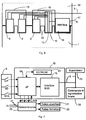
- FIG. 6 illustrates in a little more detail the arrangement of a module 10 inside a circuit breaker.
- the module 10 allows the both signaling and remote control via bus 5.
- Figure 6 is a view from above, in section, of the front face of a circuit breaker 1 fitted with a remote control unit 13. Only a connection interface 14 essential for understanding has been represented in the remote control unit 13, which is of known type.
- Auxiliary contacts 9 and module 10 are each arranged in a location 15 provided for an auxiliary contact.
- the remote control unit 13 has recesses 16 arranged, when it is mounted on the circuit breaker 1, opposite the locations 15 of the auxiliary contacts to facilitate connection. This makes it easy to replace one of the auxiliary contacts by the communication module 10, even if it is a little higher than the contacts conventional auxiliaries.
- the processing card 12 of the module 10 is electrically connected to each of the auxiliary contacts 9 and to the bus 5. In addition, it is electrically connected to a interface 14 for connecting the remote control unit. Interface 14 also has a power 17 intended for power supply (220V AC for example) of the relays opening and / or closing of the circuit breaker to which it is connected via the remote control unit.
- a power 17 intended for power supply (220V AC for example) of the relays opening and / or closing of the circuit breaker to which it is connected via the remote control unit.
- the electrical diagram of the module 10 according to FIG. 6 is shown in more detail in FIG. 7.
- the module 10 comprises on the processing card (12) a logic circuit consisting of preferably by a microprocessor 18 connected by an interface 19 or bus 5.
- the interface 19 may optionally be carried out in software form and be integrated into microprocessor 18.
- the microprocessor is also connected to the auxiliary contacts, three of which (O / F, SD, SDE) are represented in figure 7. It can thus transmit the states of these contacts to the bus 5.
- the microprocessor 18 is also connected to the remote control circuit 20 of a relay 21 for opening and a relay 22 for closing the circuit breaker. In the embodiment shown, four wires connect the microprocessor to the remote control circuit.
- sons are respectively intended for the transmission of an order to open (O), close (F) or reset (R) from module 10 to the remote control or to read by module 10 of the position of a contact (A / M), located on the front face of the remote control unit and defining the operating mode in automatic or manual remote control.
- the module 10 also includes a memory 23, preferably of the EEPROM type, associated with microprocessor 18. This memory is in particular intended to memorize the address of module 10 and the operating mode of the remote control. In one embodiment preferential, a paging process is performed automatically by a supervisor 24 via bus 5, when module 10 is energized. If no address is not stored in the EEPROM 23, or if this must be modified, the supervisor assign an address to module 10.
- control module 25 It is sometimes desirable to supplement the above device with a control module 25 and local signage.
- This is intended to be placed on the front of a switchboard in which is arranged the circuit breaker 1. It is connected directly to bus 5, at the same address as the communication module 10.
- the module 10 can be configured by the supervisor 24 to operate either in remote mode only, in which it can only be controlled by the supervisor, either in a local mode in which the circuit breaker control by the module room 25 is also allowed.
- the local mode is authorized by default, but can be locked by the supervisor who sets the parameters appropriate module 10.
- the corresponding parameter is stored in the EEPROM 23.
- the module 10 provides both signaling and remote control functions
- this can correlate these two types of functions. For example, if after sending an opening or closing order the following status of the signaling does not correspond to the given order, the module can send to bus 5 of the alarm signals representative of a remote control fault.
- the module can be configured by the supervisor to prohibit, or authorize a reset after tripping on electrical fault, signaled by the SDE auxiliary contact. It can also be configured to allow, or not, a remote reset, or a automatic reset, in the event of a trip signaled by the auxiliary contact SD.
- the module 10 continuously reads the state of the auxiliary contacts connected to it and compares them with their previous state. If this state has been changed, as well as if requested by the supervisor, the module transmits this information to the supervisor via bus 5.
Landscapes
- Engineering & Computer Science (AREA)
- Computer Networks & Wireless Communication (AREA)
- Signal Processing (AREA)
- Breakers (AREA)
- Remote Monitoring And Control Of Power-Distribution Networks (AREA)
- Selective Calling Equipment (AREA)
- Driving Mechanisms And Operating Circuits Of Arc-Extinguishing High-Tension Switches (AREA)
Abstract
Description
- Les figures 1 à 3 représentent des disjoncteurs selon l'art antérieur,
- la figure 4 illustre, sous forme schématique, la présente invention,
- la figure 5 représente un vue en perspective d'un contact auxiliaire,
- la figure 6 illustre la disposition d'un module de communication à l'intérieur d'un disjoncteur,
- la figure 7 représente schématiquement un module de communication selon l'invention et ses diverses connexions électriques.
Claims (7)
- Dispositif d'interruption électrique comportant une pluralité d'emplacements (15) pour des contacts auxiliaires dont l'état est représentatif de l'état du dispositif, au moins un contact auxiliaire (9) disposé dans l'un desdits emplacements et un module (10) de communication destiné à être connecté à un bus de communication (5), dispositif caractérisé en ce que le module de communication (10) est connecté électriquement aux contacts auxiliaires (9) et disposé à l'intérieur du dispositif (1) dans l'un desdits emplacements (15), ledit module constituant une interface de communication entre les contacts auxiliaires (9) et le bus (5).
- Dispositif selon la revendication 1, comportant des relais (21, 22) de commande d'ouverture et de fermeture du dispositif, caractérisé en ce que le module (10) est connecté électriquement auxdits relais (21, 22) de manière à permettre la télécommande du dispositif par l'intermédiaire du bus (5).
- Dispositif selon la revendication 2, caractérisé en ce que le module de communication (10) comporte un circuit logique (18) associé à des moyens (23) de mémorisation d'au moins un paramètre pouvant être modifié par l'intermédiaire du bus, ledit circuit logique recevant des contacts auxiliaires (9) des informations représentatives de l'état du dispositif d'interruption (1) et des ordres de télécommande en provenance du bus et fournissant des ordres de commande aux relais (21, 22) d'ouverture et de fermeture en fonction des ordres de télécommande, de l'état du dispositif et desdits paramètres.
- Dispositif selon la revendication 3, caractérisé en ce que le circuit logique (18) fournit une alarme si l'état du dispositif ne correspond pas aux ordres de commande.
- Dispositif selon l'une des revendications 3 et 4, caractérisé en ce que l'un desdits paramètres interdit une fermeture du dispositif par télécommande après ouverture du dispositif en réponse à un défaut électrique.
- Dispositif selon l'une quelconque des revendications 3 à 5, caractérisé en ce que l'un desdits paramètres autorise un réarmement automatique du dispositif.
- Dispositif selon l'une quelconque des revendications 3 à 6, caractérisé en ce que l'un desdits paramètre autorise la télécommande du dispositif (1) à partir d'un module de commande et de signalisation local (25) connecté au bus (5).
Applications Claiming Priority (2)
| Application Number | Priority Date | Filing Date | Title |
|---|---|---|---|
| FR9715811A FR2772203B1 (fr) | 1997-12-09 | 1997-12-09 | Dispositif d'interruption electrique comportant un module de communication |
| FR9715811 | 1997-12-09 |
Publications (2)
| Publication Number | Publication Date |
|---|---|
| EP0923185A1 true EP0923185A1 (fr) | 1999-06-16 |
| EP0923185B1 EP0923185B1 (fr) | 2009-03-25 |
Family
ID=9514567
Family Applications (1)
| Application Number | Title | Priority Date | Filing Date |
|---|---|---|---|
| EP98410116A Expired - Lifetime EP0923185B1 (fr) | 1997-12-09 | 1998-10-07 | Dispositif d'interruption électrique comportant un module de communication |
Country Status (7)
| Country | Link |
|---|---|
| US (1) | US6246928B1 (fr) |
| EP (1) | EP0923185B1 (fr) |
| JP (1) | JP2000208007A (fr) |
| CN (1) | CN1125522C (fr) |
| DE (1) | DE69840683D1 (fr) |
| ES (1) | ES2321672T3 (fr) |
| FR (1) | FR2772203B1 (fr) |
Cited By (5)
| Publication number | Priority date | Publication date | Assignee | Title |
|---|---|---|---|---|
| DE10031963C1 (de) * | 2000-06-30 | 2002-02-07 | Moeller Gmbh | Leistungsschalter |
| DE10031964C1 (de) * | 2000-06-30 | 2002-02-21 | Moeller Gmbh | Leistungsschalter |
| EP1347485A1 (fr) * | 2002-03-19 | 2003-09-24 | Schneider Electric Industries SAS | Bloc additif pour contacteur-disjoncteur. |
| EP2161733A3 (fr) * | 2008-09-04 | 2013-12-04 | General Electric Company | Actionneur de fermeture de disjoncteur et procédé de fonctionnement |
| FR2992462A1 (fr) * | 2012-06-26 | 2013-12-27 | Schneider Electric Ind Sas | Additif pour bloc de commande d'un actionneur bistable avec une commande monostable |
Families Citing this family (19)
| Publication number | Priority date | Publication date | Assignee | Title |
|---|---|---|---|---|
| JP3352411B2 (ja) * | 1998-03-05 | 2002-12-03 | 株式会社東芝 | 制御システム、電力系統保護制御システムおよびプログラムを記憶した記憶媒体 |
| US6405104B1 (en) * | 1999-03-24 | 2002-06-11 | General Electric Corporation | Fault data synchronization via peer-to-peer communications network |
| US6577963B1 (en) * | 2000-12-12 | 2003-06-10 | International Business Machines Corp. | Programmatic resetting of circuit breakers |
| US6683432B2 (en) * | 2001-09-12 | 2004-01-27 | Eigenpoint Company | Safety circuit with automatic recovery |
| JP4874480B2 (ja) * | 2001-09-28 | 2012-02-15 | 三菱電機株式会社 | 回路遮断器の監視システム |
| JP2004013450A (ja) * | 2002-06-06 | 2004-01-15 | Hitachi Ltd | 配電盤開閉装置と操作監視制御システム |
| WO2004001094A1 (fr) * | 2002-06-19 | 2003-12-31 | Tosoh Smd, Inc. | Systeme de surveillance de cible de pulverisation |
| ITBG20030005A1 (it) * | 2003-01-28 | 2004-07-29 | Abb Service Srl | Interruttore di bassa tensione comprendente una unita' di interfaccia. |
| WO2005104800A2 (fr) * | 2004-04-28 | 2005-11-10 | Stoof Ronald M | Protection de surtension modulaire |
| US7710697B2 (en) * | 2004-10-22 | 2010-05-04 | Honeywell International Inc. | Hybrid system for electronically resetable circuit protection |
| ES2298986T3 (es) * | 2005-05-13 | 2008-05-16 | Abb Research Ltd. | Dispositivo de circuito electronico para propositos de control. |
| US7692112B2 (en) * | 2006-01-10 | 2010-04-06 | Siemens Industry, Inc. | Control module |
| US8773827B2 (en) * | 2008-02-19 | 2014-07-08 | Simply Automated Incorporated | Intelligent circuit breaker apparatus and methods |
| WO2011034140A1 (fr) * | 2009-09-16 | 2011-03-24 | 株式会社ワイ・ワイ・エル | Commutateur |
| US8386108B2 (en) | 2011-03-02 | 2013-02-26 | Bombardier Transportation Gmbh | System and method of controlling supply voltage polarity on a vehicle |
| JP5225448B2 (ja) * | 2011-09-29 | 2013-07-03 | 三菱電機株式会社 | 回路遮断器 |
| US9088568B1 (en) | 2013-09-11 | 2015-07-21 | Talati Family LP | Apparatus, system and method for secure data exchange |
| US11297506B2 (en) | 2017-02-28 | 2022-04-05 | Leviton Manufacturing Co., Inc. | Communication enabled circuit breakers and circuit breaker panels |
| DE202020107235U1 (de) | 2020-12-14 | 2021-01-14 | Abb Schweiz Ag | Schützmodul und Schützmodulanordnung |
Citations (5)
| Publication number | Priority date | Publication date | Assignee | Title |
|---|---|---|---|---|
| WO1993012566A1 (fr) * | 1991-12-18 | 1993-06-24 | Square D Company | Disjoncteur electronique programmable a distance |
| EP0571898A1 (fr) * | 1992-05-29 | 1993-12-01 | Alcatel Standard Electrica, S.A. | Système disjoncteur basse tension |
| US5440088A (en) * | 1992-09-29 | 1995-08-08 | Merlin Gerin | Molded case circuit breaker with auxiliary contacts |
| DE19546268A1 (de) * | 1995-12-12 | 1997-06-19 | Kloeckner Moeller Gmbh | Busfähiger Verstärkerbaustein für Antriebsanordnungen elektromagnetischer Schaltgeräte |
| EP0792096A1 (fr) * | 1996-01-26 | 1997-08-27 | Schneider Electric Sa | Relais électronique de protection multifonctions |
Family Cites Families (6)
| Publication number | Priority date | Publication date | Assignee | Title |
|---|---|---|---|---|
| US5691619A (en) * | 1994-10-31 | 1997-11-25 | Vingsbo; Stefan G. | Automatic safety switch for preventing accidental battery discharge |
| JP3383100B2 (ja) * | 1995-02-07 | 2003-03-04 | 三菱電機株式会社 | 電力変換器の異常検出装置 |
| US5880954A (en) * | 1995-12-04 | 1999-03-09 | Thomson; Robert | Continous real time safety-related control system |
| US5859596A (en) * | 1996-08-30 | 1999-01-12 | Csi Technology, Inc. | Switchyard equipment monitoring system and communications network therefor |
| US5973898A (en) * | 1998-01-16 | 1999-10-26 | Merchant; Roger R. | Detector circuit and automatic electrical interrupt apparatus |
| US6005757A (en) * | 1998-05-11 | 1999-12-21 | Eaton Corporation | Electrical switching device or trip unit acquiring predetermined settings from another electrical switching device or trip unit |
-
1997
- 1997-12-09 FR FR9715811A patent/FR2772203B1/fr not_active Expired - Fee Related
-
1998
- 1998-10-07 EP EP98410116A patent/EP0923185B1/fr not_active Expired - Lifetime
- 1998-10-07 ES ES98410116T patent/ES2321672T3/es not_active Expired - Lifetime
- 1998-10-07 DE DE69840683T patent/DE69840683D1/de not_active Expired - Lifetime
- 1998-11-02 US US09/183,946 patent/US6246928B1/en not_active Expired - Lifetime
- 1998-11-30 JP JP10340156A patent/JP2000208007A/ja active Pending
- 1998-12-07 CN CN98123064A patent/CN1125522C/zh not_active Expired - Lifetime
Patent Citations (5)
| Publication number | Priority date | Publication date | Assignee | Title |
|---|---|---|---|---|
| WO1993012566A1 (fr) * | 1991-12-18 | 1993-06-24 | Square D Company | Disjoncteur electronique programmable a distance |
| EP0571898A1 (fr) * | 1992-05-29 | 1993-12-01 | Alcatel Standard Electrica, S.A. | Système disjoncteur basse tension |
| US5440088A (en) * | 1992-09-29 | 1995-08-08 | Merlin Gerin | Molded case circuit breaker with auxiliary contacts |
| DE19546268A1 (de) * | 1995-12-12 | 1997-06-19 | Kloeckner Moeller Gmbh | Busfähiger Verstärkerbaustein für Antriebsanordnungen elektromagnetischer Schaltgeräte |
| EP0792096A1 (fr) * | 1996-01-26 | 1997-08-27 | Schneider Electric Sa | Relais électronique de protection multifonctions |
Cited By (8)
| Publication number | Priority date | Publication date | Assignee | Title |
|---|---|---|---|---|
| DE10031963C1 (de) * | 2000-06-30 | 2002-02-07 | Moeller Gmbh | Leistungsschalter |
| DE10031964C1 (de) * | 2000-06-30 | 2002-02-21 | Moeller Gmbh | Leistungsschalter |
| DE10066242B4 (de) * | 2000-06-30 | 2009-06-10 | Moeller Gmbh | Kommunikationsfähiger Leistungsschalter |
| EP1347485A1 (fr) * | 2002-03-19 | 2003-09-24 | Schneider Electric Industries SAS | Bloc additif pour contacteur-disjoncteur. |
| FR2837618A1 (fr) * | 2002-03-19 | 2003-09-26 | Schneider Electric Ind Sa | Bloc additif pour contacteur-disjoncteur |
| US6734380B2 (en) | 2002-03-19 | 2004-05-11 | Schneider Electric Industries Sas | Add-on unit for contactor-circuit breaker |
| EP2161733A3 (fr) * | 2008-09-04 | 2013-12-04 | General Electric Company | Actionneur de fermeture de disjoncteur et procédé de fonctionnement |
| FR2992462A1 (fr) * | 2012-06-26 | 2013-12-27 | Schneider Electric Ind Sas | Additif pour bloc de commande d'un actionneur bistable avec une commande monostable |
Also Published As
| Publication number | Publication date |
|---|---|
| US6246928B1 (en) | 2001-06-12 |
| ES2321672T3 (es) | 2009-06-09 |
| CN1125522C (zh) | 2003-10-22 |
| DE69840683D1 (de) | 2009-05-07 |
| FR2772203A1 (fr) | 1999-06-11 |
| JP2000208007A (ja) | 2000-07-28 |
| FR2772203B1 (fr) | 2000-01-21 |
| EP0923185B1 (fr) | 2009-03-25 |
| CN1219793A (zh) | 1999-06-16 |
Similar Documents
| Publication | Publication Date | Title |
|---|---|---|
| EP0923185B1 (fr) | Dispositif d'interruption électrique comportant un module de communication | |
| EP0736946B1 (fr) | Module d'interface entre un bus de terrain et un appareillage électrique de commande et de protection d'un moteur électrique | |
| EP1449287B1 (fr) | Module de commande et de protection d'un appareil interrupteur | |
| EP0843332B1 (fr) | Disjoncteur avec un bloc disjoncteur et des modules de traitement, de calibrage et de communication | |
| EP0351272B1 (fr) | Moteur électrique équipé d'un moyen de jonction modulaire | |
| EP0278802A1 (fr) | Ensemble de commande et de protection connectant un réseau de communication local à un processus industriel | |
| FR2682529A1 (fr) | Disjoncteur a verrouillage selectif. | |
| EP0913020B1 (fr) | Appareillage electrique debrochable comportant une partie fixe et une partie amovible debrochable installee dans la partie fixe | |
| EP2568788B1 (fr) | Dispositif et procédé de contrôle d'appareil ou d'installation électrique, installation électrique comportant un tel dispositif | |
| FR2628873A1 (fr) | Agencement de telecontrole par voie telephonique pour installation mono ou multifonction | |
| EP0424273A1 (fr) | Procédé de maintenance d'un dispositif de contrôle des accès à un bâtiment, et dispositif de contrôle le mettant en oeuvre | |
| EP0343089B1 (fr) | Circuit d'interface téléphonique | |
| FR2580124A1 (fr) | ||
| FR2955431A1 (fr) | Dispositif de controle et de protection pour une installation electrique | |
| EP2693585B1 (fr) | Système de protection d'une pluralité de départs électriques contre des courts-circuits, et installation électrique comprenant un tel système de protection | |
| EP2999084B1 (fr) | Dispositif d'interconnexion électrique pour inverseur de source, et inverseur de source comprenant un tel dispositif | |
| EP1958298A2 (fr) | Dispositif d'interruption d'une ligne de communication de donnees | |
| FR2745910A1 (fr) | Dispositif multifonctions pour mesurer des parametres physiques d'une installation electrique basse tension en regime alternatif | |
| EP0755107A1 (fr) | Circuit de communication à signalisation de défaut et module de test associé | |
| EP3140962B1 (fr) | Système de gestion d'une structure comprenant un coffret avec connexions redondantes. | |
| FR3030921A1 (fr) | Appareillage de protection electrique destine a equiper un tableau electrique | |
| FR2788381A1 (fr) | Dispositif de protection et de gestion d'une installation electrique, notamment domestique | |
| FR2566202A1 (fr) | Dispositif de distribution d'energie | |
| FR2725557A1 (fr) | Dispositif electronique de commutation-disjonction | |
| FR2786646A1 (fr) | Interface de telecommande pour poste telephonique, permettant de transmettre une alarme et poste telephonique comprenant ladite interface |
Legal Events
| Date | Code | Title | Description |
|---|---|---|---|
| PUAI | Public reference made under article 153(3) epc to a published international application that has entered the european phase |
Free format text: ORIGINAL CODE: 0009012 |
|
| AK | Designated contracting states |
Kind code of ref document: A1 Designated state(s): DE ES GB IT |
|
| AX | Request for extension of the european patent |
Free format text: AL;LT;LV;MK;RO;SI |
|
| RAP1 | Party data changed (applicant data changed or rights of an application transferred) |
Owner name: SCHNEIDER ELECTRIC INDUSTRIES SA |
|
| 17P | Request for examination filed |
Effective date: 19991105 |
|
| AKX | Designation fees paid |
Free format text: DE ES GB IT |
|
| RAP1 | Party data changed (applicant data changed or rights of an application transferred) |
Owner name: SCHNEIDER ELECTRIC INDUSTRIES SA |
|
| RAP1 | Party data changed (applicant data changed or rights of an application transferred) |
Owner name: SCHNEIDER ELECTRIC INDUSTRIES SAS |
|
| 17Q | First examination report despatched |
Effective date: 20071015 |
|
| GRAP | Despatch of communication of intention to grant a patent |
Free format text: ORIGINAL CODE: EPIDOSNIGR1 |
|
| GRAS | Grant fee paid |
Free format text: ORIGINAL CODE: EPIDOSNIGR3 |
|
| GRAA | (expected) grant |
Free format text: ORIGINAL CODE: 0009210 |
|
| AK | Designated contracting states |
Kind code of ref document: B1 Designated state(s): DE ES GB IT |
|
| REG | Reference to a national code |
Ref country code: GB Ref legal event code: FG4D Free format text: NOT ENGLISH |
|
| RAP2 | Party data changed (patent owner data changed or rights of a patent transferred) |
Owner name: SCHNEIDER ELECTRIC INDUSTRIES SAS |
|
| REF | Corresponds to: |
Ref document number: 69840683 Country of ref document: DE Date of ref document: 20090507 Kind code of ref document: P |
|
| REG | Reference to a national code |
Ref country code: ES Ref legal event code: FG2A Ref document number: 2321672 Country of ref document: ES Kind code of ref document: T3 |
|
| PLBE | No opposition filed within time limit |
Free format text: ORIGINAL CODE: 0009261 |
|
| STAA | Information on the status of an ep patent application or granted ep patent |
Free format text: STATUS: NO OPPOSITION FILED WITHIN TIME LIMIT |
|
| 26N | No opposition filed |
Effective date: 20091229 |
|
| PGFP | Annual fee paid to national office [announced via postgrant information from national office to epo] |
Ref country code: ES Payment date: 20160915 Year of fee payment: 19 |
|
| PGFP | Annual fee paid to national office [announced via postgrant information from national office to epo] |
Ref country code: GB Payment date: 20161005 Year of fee payment: 19 Ref country code: DE Payment date: 20161007 Year of fee payment: 19 |
|
| PGFP | Annual fee paid to national office [announced via postgrant information from national office to epo] |
Ref country code: IT Payment date: 20161024 Year of fee payment: 19 |
|
| REG | Reference to a national code |
Ref country code: DE Ref legal event code: R119 Ref document number: 69840683 Country of ref document: DE |
|
| GBPC | Gb: european patent ceased through non-payment of renewal fee |
Effective date: 20171007 |
|
| PG25 | Lapsed in a contracting state [announced via postgrant information from national office to epo] |
Ref country code: GB Free format text: LAPSE BECAUSE OF NON-PAYMENT OF DUE FEES Effective date: 20171007 Ref country code: DE Free format text: LAPSE BECAUSE OF NON-PAYMENT OF DUE FEES Effective date: 20180501 |
|
| PG25 | Lapsed in a contracting state [announced via postgrant information from national office to epo] |
Ref country code: IT Free format text: LAPSE BECAUSE OF NON-PAYMENT OF DUE FEES Effective date: 20171007 |
|
| REG | Reference to a national code |
Ref country code: ES Ref legal event code: FD2A Effective date: 20181220 |
|
| PG25 | Lapsed in a contracting state [announced via postgrant information from national office to epo] |
Ref country code: ES Free format text: LAPSE BECAUSE OF NON-PAYMENT OF DUE FEES Effective date: 20171008 |