EP0923458B1 - Ventilvorrichtung für einen im nebenstrom angeordneten wärmetauscher in einem kühlkreislauf, insbesondere einer brennkraftmaschine - Google Patents
Ventilvorrichtung für einen im nebenstrom angeordneten wärmetauscher in einem kühlkreislauf, insbesondere einer brennkraftmaschine Download PDFInfo
- Publication number
- EP0923458B1 EP0923458B1 EP98932181A EP98932181A EP0923458B1 EP 0923458 B1 EP0923458 B1 EP 0923458B1 EP 98932181 A EP98932181 A EP 98932181A EP 98932181 A EP98932181 A EP 98932181A EP 0923458 B1 EP0923458 B1 EP 0923458B1
- Authority
- EP
- European Patent Office
- Prior art keywords
- valve
- pipe
- valve body
- heat exchanger
- flow
- Prior art date
- Legal status (The legal status is an assumption and is not a legal conclusion. Google has not performed a legal analysis and makes no representation as to the accuracy of the status listed.)
- Expired - Lifetime
Links
Images

Classifications
-
- F—MECHANICAL ENGINEERING; LIGHTING; HEATING; WEAPONS; BLASTING
- F01—MACHINES OR ENGINES IN GENERAL; ENGINE PLANTS IN GENERAL; STEAM ENGINES
- F01P—COOLING OF MACHINES OR ENGINES IN GENERAL; COOLING OF INTERNAL-COMBUSTION ENGINES
- F01P11/00—Component parts, details, or accessories not provided for in, or of interest apart from, groups F01P1/00 - F01P9/00
- F01P11/14—Indicating devices; Other safety devices
-
- B—PERFORMING OPERATIONS; TRANSPORTING
- B60—VEHICLES IN GENERAL
- B60H—ARRANGEMENTS OF HEATING, COOLING, VENTILATING OR OTHER AIR-TREATING DEVICES SPECIALLY ADAPTED FOR PASSENGER OR GOODS SPACES OF VEHICLES
- B60H1/00—Heating, cooling or ventilating devices
- B60H1/00485—Valves for air-conditioning devices, e.g. thermostatic valves
-
- B—PERFORMING OPERATIONS; TRANSPORTING
- B60—VEHICLES IN GENERAL
- B60H—ARRANGEMENTS OF HEATING, COOLING, VENTILATING OR OTHER AIR-TREATING DEVICES SPECIALLY ADAPTED FOR PASSENGER OR GOODS SPACES OF VEHICLES
- B60H1/00—Heating, cooling or ventilating devices
- B60H1/00642—Control systems or circuits; Control members or indication devices for heating, cooling or ventilating devices
- B60H1/00978—Control systems or circuits characterised by failure of detection or safety means; Diagnostic methods
-
- F—MECHANICAL ENGINEERING; LIGHTING; HEATING; WEAPONS; BLASTING
- F01—MACHINES OR ENGINES IN GENERAL; ENGINE PLANTS IN GENERAL; STEAM ENGINES
- F01P—COOLING OF MACHINES OR ENGINES IN GENERAL; COOLING OF INTERNAL-COMBUSTION ENGINES
- F01P2031/00—Fail safe
-
- Y—GENERAL TAGGING OF NEW TECHNOLOGICAL DEVELOPMENTS; GENERAL TAGGING OF CROSS-SECTIONAL TECHNOLOGIES SPANNING OVER SEVERAL SECTIONS OF THE IPC; TECHNICAL SUBJECTS COVERED BY FORMER USPC CROSS-REFERENCE ART COLLECTIONS [XRACs] AND DIGESTS
- Y10—TECHNICAL SUBJECTS COVERED BY FORMER USPC
- Y10T—TECHNICAL SUBJECTS COVERED BY FORMER US CLASSIFICATION
- Y10T137/00—Fluid handling
- Y10T137/2496—Self-proportioning or correlating systems
- Y10T137/2559—Self-controlled branched flow systems
- Y10T137/2562—Dividing and recombining
-
- Y—GENERAL TAGGING OF NEW TECHNOLOGICAL DEVELOPMENTS; GENERAL TAGGING OF CROSS-SECTIONAL TECHNOLOGIES SPANNING OVER SEVERAL SECTIONS OF THE IPC; TECHNICAL SUBJECTS COVERED BY FORMER USPC CROSS-REFERENCE ART COLLECTIONS [XRACs] AND DIGESTS
- Y10—TECHNICAL SUBJECTS COVERED BY FORMER USPC
- Y10T—TECHNICAL SUBJECTS COVERED BY FORMER US CLASSIFICATION
- Y10T137/00—Fluid handling
- Y10T137/7722—Line condition change responsive valves
- Y10T137/7723—Safety cut-off requiring reset
- Y10T137/7726—Responsive to change in rate of flow
- Y10T137/7727—Excessive flow cut-off
-
- Y—GENERAL TAGGING OF NEW TECHNOLOGICAL DEVELOPMENTS; GENERAL TAGGING OF CROSS-SECTIONAL TECHNOLOGIES SPANNING OVER SEVERAL SECTIONS OF THE IPC; TECHNICAL SUBJECTS COVERED BY FORMER USPC CROSS-REFERENCE ART COLLECTIONS [XRACs] AND DIGESTS
- Y10—TECHNICAL SUBJECTS COVERED BY FORMER USPC
- Y10T—TECHNICAL SUBJECTS COVERED BY FORMER US CLASSIFICATION
- Y10T137/00—Fluid handling
- Y10T137/7722—Line condition change responsive valves
- Y10T137/7837—Direct response valves [i.e., check valve type]
- Y10T137/7838—Plural
- Y10T137/7841—One valve carries head and seat for second valve
-
- Y—GENERAL TAGGING OF NEW TECHNOLOGICAL DEVELOPMENTS; GENERAL TAGGING OF CROSS-SECTIONAL TECHNOLOGIES SPANNING OVER SEVERAL SECTIONS OF THE IPC; TECHNICAL SUBJECTS COVERED BY FORMER USPC CROSS-REFERENCE ART COLLECTIONS [XRACs] AND DIGESTS
- Y10—TECHNICAL SUBJECTS COVERED BY FORMER USPC
- Y10T—TECHNICAL SUBJECTS COVERED BY FORMER US CLASSIFICATION
- Y10T137/00—Fluid handling
- Y10T137/8593—Systems
- Y10T137/87265—Dividing into parallel flow paths with recombining
- Y10T137/87273—With fluid coupling [e.g., railway car hose coupling, truck-trailer oil system coupling, etc.]
Definitions
- the invention relates to a valve device arranged in a secondary flow for a valve in the secondary flow arranged heat exchanger in a cooling circuit, in particular one Internal combustion engine.
- Such a valve device is for example from DE 196 27 655 A Heating device for a vehicle is known.
- the generic valve device is arranged in a bypass of heating heat exchangers for the purpose of hot water inlet pressure to be kept at a constant level with every heat exchanger.
- the valve body used in the valve device has a throttle passage with the aim of one in the bypass with the valve body closed Maintain hot water circulation.
- Another valve device is known from EP-A 0 302 264.
- the subject of this document is intended to especially when the internal combustion engine is idling in the downstream heat exchanger maximum heat transfer take place. This is achieved by that the coolant throughput is almost not throttled when the engine is idling is. No further details are given for higher pump pressures.
- the invention has for its object the generic valve device to further develop that the inlet or delivery pressure when reaching the maximum Heat transfer in the coolant throughput causing the heat exchanger is limited when the heat exchanger continues to flow, and that with this flow-controlled Pressure load a safety device effective depending on the funding is combined.
- valve device is used in addition to flow control pressure limitation achieved additionally as a first, per se e.g. from DE-B 1 172 918 known pipe or hose rupture valve, its flow shut-off function in a motor vehicle with a liquid-cooled engine with in whose cooling circuit is integrated in bypasses for different purposes Heat exchangers in the event of a pipe or hose break the relevant branch circuit separates from the rest of the cooling circuit, the vehicle advantageously remains operational.
- the valve device is provided with a Pipe or hose rupture valve equipped such that the one with the throttle passage trained valve body is slidably disposed in a Sliding sleeve with valve seat, which in the housing between pipe or Hose connector with the valve body lying essentially tightly against the valve seat Depending on the discharge pressure against a compression spring in a tight stop with the housing is brought, with the delivery pressure side through a pipe or hose break triggered further stop movement of the sliding sleeve downstream in the pipe or hose connector fixedly arranged elastic element the throttle passage closes.
- a combined pressure relief and safety valve in a housing a return chamber from a valve opening having dividing wall divided flow chamber separating membrane with a valve body controlling the valve opening on the downstream side with throttle passages and the valve opening in the event of a pipe or hose break upstream closing valve plate is in drive connection, and that in a check valve on the heat exchanger side of the housing is arranged.
- a third valve device is advantageously simple in design, that the valve body even in the event of a line break as a pipe or hose break valve acts and thus only a separate one in the secondary flow in the other line Pipe or hose rupture valve is required.
- Valve device With the advantageous first described in terms of construction effort and space Valve device is used to achieve the safety function in a pipe or Broken hose requires a corresponding delivery pressure in the cooling circuit, whereby in the somewhat more complex second embodiment of the valve device Safety function due to a diaphragm acting on the return chamber side Closing spring is ensured.
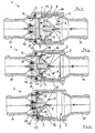
- a first embodiment of a valve device 1 for a not shown separate heat exchanger cooling circuit of an internal combustion engine, not shown comprises in a housing 2 depending on the delivery pressure against the Resistance of a return spring 3 relative to a line cross section 4 delimiting Valve seat 5 controlled valve body 6 and a throttle passage 7.
- the inlet or delivery pressure to one with reaching a Maximum heat transfer in the coolant throughput causing the respective heat exchanger limit the corresponding value while maintaining it of the coolant throughput given for the maximum heat transfer is the valve body 6 according to the invention when the coolant throughput is reached for maximum heat transfer in the downstream Heat exchanger controlled by the valve seat 5 in the closed position depending on the delivery pressure, the proposed throttle passage 7 has a cross section 4, over which one essentially corresponds to the maximum heat transfer Coolant flow is maintained.
- the valve device 1 acts to the extent described above as a flow control valve with controlled pressure limitation for a downstream heat exchanger, its application beyond the maximum heat transfer is advantageously reduced, combined with an advantageous pressure relief of the heat exchanger with higher operational reliability and a longer service life. Offers further the valve device 1 according to the invention with several heat exchangers in the cooling circuit the internal combustion engine needs-based distribution of the coolant flows.
- the Figure 3 shows that with the closing of the throttle passage 7 a Valve body 6 and the sliding sleeve 8 each holding in the tight closed position Fixing device 15 takes effect.
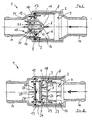
- Valve device 1 serves to limit the pressure Valve device 1 is advantageously also the safety function of a Hose or pipe break valve achieved. If a connecting line is damaged in the course of the secondary flow downstream of the valve device 1 to one Heat exchanger is thus a further coolant supply to this heat exchanger prevented, with a further loss of coolant from the cooling circuit via the intact return flow of the secondary flow by means of a further pipe or hose rupture valve is avoided, which is preferred in a structurally simple manner as a check valve is designed, e.g. with the check valve 39 of the valve device 1 'is shown in Figures 6 and 7.
- valve effective valve device 1 is an idling of the Cooling circuit prevented, so that the cooling circuit with the rest properly connected heat exchangers, including the internal combustion engine, remains fully functional. Furthermore, this valve device 1 ensures that each after arranging a defective heat exchanger or a defective connecting line only the content of this heat exchanger may be in Vehicle interior can spread.
- the feed pressure points to Flow control adjustable valve body 6 for controlling the coolant throughput in a downstream heat exchanger a conical upstream and slidably arranged in the sliding sleeve 8 via distributed wings 16 guided closure body 17 with a sealing seat 18, the in his Throttle cross-section on the throttle characteristic of the downstream heat exchanger Parked throttle passage 7 in a downstream position, in the closed position of valve body 6 and sliding sleeve 8 projecting beyond the valve seat 5 Extension 19 is arranged, with locking points for locking tongues 20 of the fixing device 15 is formed. With this fixing device 15 it is ensured that the valve device 1 even at low or strongly fluctuating delivery pressure in Cooling circuit is kept perfectly tight.
- valve device 1 differs from the valve device 1 of Figures 1 with 3 by a modified Fixing device 15.
- This comprises elastic elements arranged on the valve body 6 Locking bracket 21 with a support plate carrying the closure element 14 22 in the downstream pipe or hose connector 11 for fixing the valve body 6 and sliding sleeve 8 cooperate.
- valve body 6 has a cup-shaped design on the inflow side via distributed wings 16 in the sliding sleeve 8 slidably guided Closure body 23 with a throttle passage 7 arranged in the bottom 24, that on a downstream side plate 25 with one of the sliding sleeve 8 applied sealing ring 26 a protruding designed closure element 27 is assigned, and furthermore the plate 25 is provided with openings 28 is for reaching through latching hooks 29 arranged on the valve body 6.
- Each of the fixing devices 15 shown in FIG. 1 with 5 is designed such that that valve body 6 and sliding sleeve 8 in the event of a defective repair Connection line between valve device 1 and assigned heat exchanger can be easily solved by hand.
- the valve device 1 'shown in FIGS. 6 and 7 with the combined functions a pressure limitation caused by a flow control and one Safety valve in the event of hose or pipe breakage comprises a housing 30 with a Return chamber 31, of a partition having a valve opening 4 ' 32 divided flow chamber 33 is separated by a membrane 34 which with a valve body 35 controlling the valve opening 4 'on the outflow side, with throttle passages 36 and a valve opening 4 'in the event of a pipe or hose break upstream valve plate 37 is in drive connection. Furthermore, the valve device 1 'has a return pipe on the heat exchanger side 38 of the housing 30 a check valve 39.
- valve device 1 ' is designed such that at one as indicated in Figure 7 for the heat exchanger flow 43 pipe or Broken hose with check valve 39 closed in the return 38 a valve stem 44 of the valve body 35 arranged valve plate 37 via a closing spring 45 acting on the return chamber side against the diaphragm 34 valve body-side compression spring 40 controlled in the closed position of the valve opening 4 ' is.
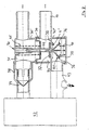
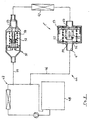
- valve device 1 which is advantageously simple in construction, it is shown in FIG a return 46 with the cooling circuit 47 of an internal combustion engine 48 connected side stream 49 arranged.
- This valve device 1 "comprises one Valve body 50, which on the one hand depends on the delivery pressure in the closed position with the valve seat 51 controlled throttle passages 52 in effect and the other hand a pipe or hose break upstream of the valve device 1 "controlled by spring force in a closed position serving as a pipe or hose rupture valve - otherwise corresponds to the starting position shown in FIG.
- the housing 53 cooperates closely, with a further one, in the flow 54 of the secondary flow 49 arranged pipe or hose rupture valve 55 a passage 56 depending on the delivery pressure controlled closes via an elastic lip seal 57 in Front edge area of the flow 56 into which the pipe or hose rupture valve 55 engage locking tabs 58.
- the spring-loaded Valve body 50 itself the pipe or hose rupture valve that in connection with the further pipe or hose rupture valve arranged in the flow 54 55 if the flow 54 is damaged upstream of the heat exchanger 42 or damage to the line of the return 46 downstream of the heat exchanger 42 largely prevents coolant loss in the cooling circuit 47 of the internal combustion engine 48 prevents.
Landscapes
- Engineering & Computer Science (AREA)
- Mechanical Engineering (AREA)
- Physics & Mathematics (AREA)
- Thermal Sciences (AREA)
- Chemical & Material Sciences (AREA)
- Combustion & Propulsion (AREA)
- General Engineering & Computer Science (AREA)
- Safety Valves (AREA)
Description
- Figuren 1 bis 3
- eine erste erfindungsgemäße Ventilvorrichtung in Aufbau und Funktionsweise, vorzugsweise angeordnet in einem Nebenstrom-Verlauf,
- Figur 4
- eine hinsichtlich der Fixiereinrichtung abgewandelte erste Ventilvorrichtung,
- Figur 5
- eine weitere Variante der ersten Ventilvorrichtung in vereinfachtem Aufbau,
- Figur 6
- eine zweite erfindungsgemäße Ventilvorrichtung mit einem über eine Membrane gesteuerten Ventilkörper, im Betrieb gezeigt, und
- Figur 7
- die zweite Ventilvorrichtung in der Funktion als Sicherheitsventil bei einem Rohr- bzw. Schlauchbruch,
- Figur 8
- eine dritte erfindungsgemäße Ventilvorrichtung im Nebenstrom-Rücklauf.
Claims (10)
- In einem Nebenstrom angeordnete Ventilvorrichtung für einen im Nebenstrom angeordneten Wärmetauscher in einem Kühlkreislauf, insbesondere einer Brennkraftmaschine,umfassend in einem Gehäuse (2, 30, 53) der Ventilvorrichtung (1, 1', 1") einen förderdruckabhängig gegen den Widerstand einer Rückstellfeder (3, 45) relativ zu einem einen Leitungsquerschnitt (4, 4', 4") begrenzenden Ventilsitz (5, 51) gesteuerten Ventilkörper (6, 35, 50) mit einem zur durchflußgeregelten Druckbegrenzung dienenden Drosseldurchgang (7, 36, 52), dadurch gekennzeichnet, daßder Ventilkörper (6, 35, 50) mit Erreichen eines Kühlmitteldurchsatzes für eine maximale Wärmeübertragung im zugeordneten Wärmetauscher (42) förderdruckabhängig in Schließstellung mit dem Ventilsitz (5, 51) gesteuert ist und der Drosseldurchgang (7, 36, 52) einen auf diese maximale Wärmeübertragung abgestimmten Querschnitt aufweist, unddaß die Ventilvorrichtung (1, 1', 1") mit einem Rohr- bzw. Schlauchbruchventil (55) kombiniert ist, dasbei einem Rohr- bzw. Schlauchbruch im Nebenstrom des Wärmetauschers (42) den Kühlmittel-Durchlaß mittels eines weiteren Verschlußelementes (14, 27, 37, 57) unterbindet.
- Ventilvorrichtung nach Anspruch 1, dadurch gekennzeichnet,daß ein mit dem Drosseldurchgang (7) ausgebildeter Ventilkörper (6) gleitbeweglich angeordnet ist in einer den Ventilsitz (5) aufweisenden Schiebehülse (8), diein dem Gehäuse (2) zwischen Rohr- bzw. Schlauchstutzen (10, 11) bei am Ventilsitz (5) im wesentlichen dicht anliegendem Ventilkörper (6) förderdruckabhängig bei einem Rohr- bzw. Schlauchbruch gegen eine Druckfeder (12) in dichtem Anschlag (Dichtring 13) mit dem Gehäuse (2) gebracht ist, wobeimit der Anschlagbewegung der Schiebehülse (8) ein stromab im Rohr- bzw. Schlauchstutzen (11) ortsfest angeordnetes elastisches Element (14) den Drosseldurchgang (7) verschließt.
- Ventilvorrichtung nach Anspruch 1 und 2, dadurch gekennzeichnet, daß mit dem Verschließen des Drosseldurchganges (7) eine den Ventilkörper (6) und die Schiebehülse (8) jeweils in dichter Schließstellung haltende Fixiereinrichtung (15) in Wirkung tritt.
- Ventilvorrichtung nach den Ansprüchen 1 bis 3, dadurch gekennzeichnet,daß der Ventilkörper (6) einen zuströmseitig konischen und über verteilt angeordnete Flügel (16) in der Schiebehülse (8) gleitbeweglich geführten Verschlußkörper (17) mit einem Dichtsitz (18) aufweist, unddaß der Drosseldurchgang (7) in einem abströmseitig vorgesehenen, in Schließstellung von Ventilkörper (6) und Schiebehülse (8) über den Ventilsitz (5) hinausragenden Fortsatz (19) angeordnet ist, dermit Raststellen für Rastzungen (20) der Fixiereinrichtung (15) ausgebildet ist (Figuren 1 bis 3).
- Ventilvorrichtung nach den Ansprüchen 1 bis 3, dadurch gekennzeichnet,daß der Ventilkörper (6) einen zuströmseitig konischen und über verteilt angeordnete Flügel (16) in der Schiebehülse (8) gleitbeweglich geführten Verschlußkörper (17) mit einem Dichtsitz (18) aufweist, undder Drosseldurchgang (7) in einem abströmseitig vorgesehenen, in Schließstellung von Ventilkörper (6) und Schiebehülse (8) über den Ventilsitz (5) hinausragenden Fortsatz (19) zum dichten Anliegen am elastischen Verschluß-Element (14) angeordnet ist, wobeiam Ventilkörper (6) angeordnete elastische Rastbügel (21) mit einer das Verschluß-Element (14) tragenden Stützplatte (22) zur Fixierung zusammenwirken (Figur 4).
- Ventilvorrichtung nach den Ansprüchen 1 bis 3, dadurch gekennzeichnet,daß der Ventilkörper (6) einen zuströmseitig topfförmig gestalteten und über verteilt angeordnete Flügel (16) in der Schiebehülse (8) gleitbeweglich geführten Verschlußkörper (23) mit einem in Boden (24) angeordneten Drosseldurchgang (7) aufweist, demauf einer abströmseitig angeordneten Platte (25) mit einem von der Schiebehülse (8) beaufschlagten Dichtring (26) ein vorspringend gestaltetes Verschluß-Element (27) zugeordnet ist, und fernerdie Platte (25) mit Durchbrechungen (28) versehen ist zum Durchgriff von am Ventilkörper (6) angeordneten Rasthaken (29) (Figur 5).
- Ventilvorrichtung nach den Ansprüchen 1 bis 6, dadurch gekennzeichnet, daß im Rücklauf des Nebenstromes des Wärmetauschers (42) als Rohr- bzw. Schlauchbruchventil ein Rückschlagventil (39) angeordnet ist.
- Ventilvorrichtung nach Anspruch 1, dadurch gekennzeichnet,daß in einem Gehäuse (30) eine eine Rücklaufkammer (31) von einer eine Ventilöffnung (4') aufweisenden Trennwand (32) unterteilten Vorlaufkammer (33) trennende Membrane (34) mit einem die Ventilöffnung (4') abströmseitig steuernden Ventilkörper (35) mit Drosseldurchgängen (36) und einem die Ventilöffnung (4') bei einem Rohr- bzw. Schlauchbruch zuströmseitig verschließenden Ventilteller (37) in Antriebsverbindung steht, unddaß in einem wärmetauscherseitigen Rücklaufstutzen (38) des Gehäuses (30) ein Rückschlagventil (39) angeordnet ist (Figur 6, 7).
- Ventilvorrichtung nach Anspruch 8, dadurch gekennzeichnet,daß die zwischen Gehäuseteilen (30', 30") eingespannt und rücklaufkammerseitig geführt angeordnete Membrane (34) förderdruckabhängig mit Unterstützung einer am Ventilkörper (35) angreifenden Druckfeder (40) den Ventilkörper (35) mit im Dichtsitz (41) ausgebildeten Drosseldurchgängen (36) steuert, unddaß bei einem Rohr- bzw. Schlauchbruch mit im Rücklauf (38) geschlossenem Rückschlagventil (39) der an einem Ventilschaft (44) des Ventilkörpers (35) angeordnete Ventilteller (37) über eine rücklaufkammerseitig auf die Membrane (34) einwirkende Schließfeder (45) gegen die ventilkörperseitige Druckfeder (40) in Schließstellung der Ventilöffnung (31) gesteuert ist.
- Ventilvorrichtung nach Anspruch 1, dadurch gekennzeichnet,daß in einem Rücklauf (46) eines mit dem Kühlkreislauf (47) einer Brennkraftmaschine (48) verbundenen Nebenstroms (49) eine Ventilvorrichtung (1") angeordnet ist, dessenVentilkörper (50) einerseits förderdruckabhängig in Schließstellung mit dem Ventilsitz (51) gesteuert Drosseldurchgänge (52) in Wirkung bringt und derandererseits bei einem Rohr- bzw. Schlauchbruch stromauf der Ventilvorrichtung (1") federkraftgesteuert in eine als Rohr- bzw. Schlauchbruchventil dienende Schließstellung gebracht mit dem Gehäuse (53) dicht zusammenwirkt, wobei hierbeiein weiteres, im Vorlauf (54) des Nebenstroms (49) angeordnetes Rohr- bzw. Schlauchbruchventil (55) einen Durchfluß (56) förderdruckabhängig gesteuert verschließt über eine elastische Lippendichtung (57) im Stirnrandbereich des Durchflusses (56), in dendas Rohr- bzw. Schlauchbruchventil (55) fixierende Rastzungen (58) eingreifen.
Applications Claiming Priority (3)
| Application Number | Priority Date | Filing Date | Title |
|---|---|---|---|
| DE19728722 | 1997-07-04 | ||
| DE19728722 | 1997-07-04 | ||
| PCT/EP1998/003852 WO1999001306A1 (de) | 1997-07-04 | 1998-06-24 | Ventilvorrichtung für einen im nebenstrom angeordneten wärmetauscher in einem kühlkreislauf, insbesondere einer brennkraftmaschine |
Publications (2)
| Publication Number | Publication Date |
|---|---|
| EP0923458A1 EP0923458A1 (de) | 1999-06-23 |
| EP0923458B1 true EP0923458B1 (de) | 2001-11-14 |
Family
ID=7834724
Family Applications (1)
| Application Number | Title | Priority Date | Filing Date |
|---|---|---|---|
| EP98932181A Expired - Lifetime EP0923458B1 (de) | 1997-07-04 | 1998-06-24 | Ventilvorrichtung für einen im nebenstrom angeordneten wärmetauscher in einem kühlkreislauf, insbesondere einer brennkraftmaschine |
Country Status (4)
| Country | Link |
|---|---|
| US (1) | US6000421A (de) |
| EP (1) | EP0923458B1 (de) |
| DE (1) | DE59802135D1 (de) |
| WO (1) | WO1999001306A1 (de) |
Cited By (1)
| Publication number | Priority date | Publication date | Assignee | Title |
|---|---|---|---|---|
| EP1364818A1 (de) * | 2002-05-20 | 2003-11-26 | TGK Co., Ltd. | Ausflussverhinderungsvorrichtung |
Families Citing this family (9)
| Publication number | Priority date | Publication date | Assignee | Title |
|---|---|---|---|---|
| US6758052B2 (en) | 2002-07-02 | 2004-07-06 | Delphi Technologies, Inc. | HVAC system with post-shut down isolation and venting of evaporator using H-shaped valve |
| JP2004270975A (ja) * | 2003-03-06 | 2004-09-30 | Tgk Co Ltd | 流量制御弁 |
| DE102006058072A1 (de) * | 2006-12-07 | 2008-06-19 | Mahle International Gmbh | Kurbelgehäuseentlüftung |
| US20110073285A1 (en) * | 2009-09-30 | 2011-03-31 | Gm Global Technology Operations, Inc. | Multi-Zone Heat Exchanger for Use in a Vehicle Cooling System |
| DE102011080474A1 (de) * | 2011-08-05 | 2013-02-07 | Behr Gmbh & Co. Kg | Wärmetauscheranordnung |
| FR2990898B1 (fr) * | 2012-05-23 | 2015-02-20 | Peugeot Citroen Automobiles Sa | Boucle hydraulique du circuit de refroidissement d'un vehicule |
| CN106481436B (zh) * | 2015-08-25 | 2020-05-15 | 康明斯公司 | 用于发动机的滤头的冷却组件 |
| BR112018006451A2 (pt) * | 2015-10-02 | 2018-10-09 | Kendrion Markdorf Gmbh | disposição de circuito de refrigeração, bem como processo para refrigeração de um motor |
| DE102021208121A1 (de) * | 2021-07-28 | 2023-02-02 | Robert Bosch Gesellschaft mit beschränkter Haftung | Heizgerät mit einer Bypassleitung sowie Einrichtung für ein Heizgerät |
Family Cites Families (15)
| Publication number | Priority date | Publication date | Assignee | Title |
|---|---|---|---|---|
| US2357321A (en) * | 1941-05-16 | 1944-09-05 | Acrotorque Co | Control |
| US2509504A (en) * | 1945-11-06 | 1950-05-30 | Garrett Corp Aires Mfg Company | Cooler failure automatic by-pass valve |
| US2960996A (en) * | 1957-05-07 | 1960-11-22 | Cherry Burrell Corp | Vacuum relief valve |
| DE1172918B (de) | 1962-11-17 | 1964-06-25 | Emil Schenk | Federbelastetes Rohrbruchventil |
| US3741241A (en) * | 1971-07-29 | 1973-06-26 | Eaton Corp | Hydraulic fuse |
| GB2165030B (en) * | 1984-09-05 | 1988-01-13 | Austin Rover Group | A valve |
| DE3715003A1 (de) * | 1987-05-06 | 1988-11-17 | Kloeckner Humboldt Deutz Ag | Kuehlsystem fuer eine fluessigkeitsgekuehlte brennkraftmaschine |
| US4800925A (en) | 1987-08-05 | 1989-01-31 | Ranco Incorporated Of Delaware | Automobile coolant flow control |
| US4874010A (en) * | 1988-05-26 | 1989-10-17 | Siemens-Bendix Automotive Electronics Limited | Heater control valve |
| CA2090116C (en) * | 1990-08-23 | 2001-02-13 | Joseph Abrams | Fluid conduit safety system |
| US5357998A (en) * | 1990-08-23 | 1994-10-25 | Woodland Technologies, Inc. | Safety system for fluid conduit |
| DE4226531A1 (de) * | 1992-08-11 | 1994-02-17 | Bosch Gmbh Robert | Taktventil zur diskontinuierlichen Dosierung eines Volumenstroms |
| US5271559A (en) * | 1992-09-03 | 1993-12-21 | Chrysler Corporation | Thermal isolation device for heater core to prevent over-heat damage |
| JP3322016B2 (ja) * | 1994-08-29 | 2002-09-09 | 株式会社デンソー | 自動車用温水式暖房装置 |
| JP3596099B2 (ja) | 1995-07-10 | 2004-12-02 | 株式会社デンソー | 暖房装置 |
-
1998
- 1998-06-24 EP EP98932181A patent/EP0923458B1/de not_active Expired - Lifetime
- 1998-06-24 DE DE59802135T patent/DE59802135D1/de not_active Expired - Lifetime
- 1998-06-24 WO PCT/EP1998/003852 patent/WO1999001306A1/de not_active Ceased
-
1999
- 1999-03-04 US US09/262,302 patent/US6000421A/en not_active Expired - Lifetime
Cited By (1)
| Publication number | Priority date | Publication date | Assignee | Title |
|---|---|---|---|---|
| EP1364818A1 (de) * | 2002-05-20 | 2003-11-26 | TGK Co., Ltd. | Ausflussverhinderungsvorrichtung |
Also Published As
| Publication number | Publication date |
|---|---|
| US6000421A (en) | 1999-12-14 |
| WO1999001306A1 (de) | 1999-01-14 |
| DE59802135D1 (de) | 2001-12-20 |
| EP0923458A1 (de) | 1999-06-23 |
Similar Documents
| Publication | Publication Date | Title |
|---|---|---|
| DE69817213T2 (de) | Thermostatventil | |
| DE10103112B4 (de) | Kraftstoff-Druckregler | |
| DE69608777T2 (de) | Sicherheitsventilanordnung für eine Fluidverdrängeranlage | |
| DE60020731T2 (de) | Kraftstoffrückführventil mit entlüftung | |
| DE2701840A1 (de) | Temperaturempfindliches nebenstrom- ventil | |
| DE9109600U1 (de) | Thermostatventil mit einem Vorsteuerventil | |
| EP1210165B1 (de) | Filter mit ventil-kombinationsbauteil | |
| DE69509715T2 (de) | Druckregulierungsventil | |
| EP0923458A1 (de) | Ventilvorrichtung für einen im nebenstrom angeordneten wärmetauscher in einem kühlkreislauf, insbesondere einer brennkraftmaschine | |
| EP0376150A2 (de) | Brennkraftmaschine mit zwei hydraulischen Flüssigkeitskreisläufen | |
| DE69001753T2 (de) | Flüssigkeitsfilter mit kurzschlussventil. | |
| DE60003752T2 (de) | Pulsationsdämpfer mit integriertem Wärmestau-Druckregelventil | |
| DE2623621B1 (de) | Einrichtung zum beheizen der bedienungskabine einer maschine | |
| DE3514198A1 (de) | Einrichtung zum beheizen des fahrgastraumes eines kraftfahrzeuges | |
| EP1350551B1 (de) | Ventilanordnung, insbesondere für den Schmierölkreislauf einer Brennkraftmaschine, beinhaltend ein Rücklaufsperrventil sowie ein Umgehungsventil | |
| EP0694681B1 (de) | Thermostatventil für den Kühlmittelkreis einer Brennkraftmaschine | |
| DE102015106476B4 (de) | Schmierölsystem einer Brennkraftmaschine | |
| DE3415876A1 (de) | Regelventil fuer den kuehlmittelkreislauf eines verbrennungsmotors, insbesondere eines kraftfahrzeuges | |
| EP1560636B1 (de) | Fluessigkeitsfilter, insbesondere oelfilter fuer kraftfahrzeuge | |
| EP0262598B1 (de) | Brennkraftmaschine | |
| EP0525311A1 (de) | Druckgesteuerte Ventileinrichtung an dem Kühlflüssigkeitskreislauf eines Verbrennungsmotors | |
| DE102004035344B4 (de) | Thermostatventil | |
| DE102016014718A1 (de) | Ventilmodul für einen Ölkreislauf einer Verbrennungskraftmaschine | |
| DE10232654B3 (de) | Gasdurchflussregeleinrichtung | |
| WO2006092655A2 (de) | Vorrichtung zur dynamischen regelung eines wasserflusses |
Legal Events
| Date | Code | Title | Description |
|---|---|---|---|
| PUAI | Public reference made under article 153(3) epc to a published international application that has entered the european phase |
Free format text: ORIGINAL CODE: 0009012 |
|
| 17P | Request for examination filed |
Effective date: 19990201 |
|
| AK | Designated contracting states |
Kind code of ref document: A1 Designated state(s): DE FR GB IT |
|
| 17Q | First examination report despatched |
Effective date: 20001113 |
|
| GRAG | Despatch of communication of intention to grant |
Free format text: ORIGINAL CODE: EPIDOS AGRA |
|
| GRAG | Despatch of communication of intention to grant |
Free format text: ORIGINAL CODE: EPIDOS AGRA |
|
| GRAH | Despatch of communication of intention to grant a patent |
Free format text: ORIGINAL CODE: EPIDOS IGRA |
|
| GRAH | Despatch of communication of intention to grant a patent |
Free format text: ORIGINAL CODE: EPIDOS IGRA |
|
| GRAA | (expected) grant |
Free format text: ORIGINAL CODE: 0009210 |
|
| AK | Designated contracting states |
Kind code of ref document: B1 Designated state(s): DE FR GB IT |
|
| GBT | Gb: translation of ep patent filed (gb section 77(6)(a)/1977) |
Effective date: 20011114 |
|
| REF | Corresponds to: |
Ref document number: 59802135 Country of ref document: DE Date of ref document: 20011220 |
|
| REG | Reference to a national code |
Ref country code: GB Ref legal event code: IF02 |
|
| ET | Fr: translation filed | ||
| PLBE | No opposition filed within time limit |
Free format text: ORIGINAL CODE: 0009261 |
|
| STAA | Information on the status of an ep patent application or granted ep patent |
Free format text: STATUS: NO OPPOSITION FILED WITHIN TIME LIMIT |
|
| 26N | No opposition filed | ||
| REG | Reference to a national code |
Ref country code: FR Ref legal event code: TP |
|
| REG | Reference to a national code |
Ref country code: GB Ref legal event code: 732E |
|
| PGFP | Annual fee paid to national office [announced via postgrant information from national office to epo] |
Ref country code: IT Payment date: 20120626 Year of fee payment: 15 |
|
| PG25 | Lapsed in a contracting state [announced via postgrant information from national office to epo] |
Ref country code: IT Free format text: LAPSE BECAUSE OF NON-PAYMENT OF DUE FEES Effective date: 20130624 |
|
| REG | Reference to a national code |
Ref country code: FR Ref legal event code: PLFP Year of fee payment: 19 |
|
| REG | Reference to a national code |
Ref country code: FR Ref legal event code: PLFP Year of fee payment: 20 |
|
| PGFP | Annual fee paid to national office [announced via postgrant information from national office to epo] |
Ref country code: FR Payment date: 20170621 Year of fee payment: 20 Ref country code: DE Payment date: 20170624 Year of fee payment: 20 Ref country code: GB Payment date: 20170626 Year of fee payment: 20 |
|
| REG | Reference to a national code |
Ref country code: DE Ref legal event code: R071 Ref document number: 59802135 Country of ref document: DE |
|
| REG | Reference to a national code |
Ref country code: GB Ref legal event code: PE20 Expiry date: 20180623 |
|
| PG25 | Lapsed in a contracting state [announced via postgrant information from national office to epo] |
Ref country code: GB Free format text: LAPSE BECAUSE OF EXPIRATION OF PROTECTION Effective date: 20180623 |