EP0924004A2 - Procédé et machine de formage de bords de pièces cintrées - Google Patents
Procédé et machine de formage de bords de pièces cintrées Download PDFInfo
- Publication number
- EP0924004A2 EP0924004A2 EP98123722A EP98123722A EP0924004A2 EP 0924004 A2 EP0924004 A2 EP 0924004A2 EP 98123722 A EP98123722 A EP 98123722A EP 98123722 A EP98123722 A EP 98123722A EP 0924004 A2 EP0924004 A2 EP 0924004A2
- Authority
- EP
- European Patent Office
- Prior art keywords
- shaping
- edges
- roll
- machine
- piece
- Prior art date
- Legal status (The legal status is an assumption and is not a legal conclusion. Google has not performed a legal analysis and makes no representation as to the accuracy of the status listed.)
- Withdrawn
Links
Images

Classifications
-
- B—PERFORMING OPERATIONS; TRANSPORTING
- B21—MECHANICAL METAL-WORKING WITHOUT ESSENTIALLY REMOVING MATERIAL; PUNCHING METAL
- B21C—MANUFACTURE OF METAL SHEETS, WIRE, RODS, TUBES, PROFILES OR LIKE SEMI-MANUFACTURED PRODUCTS OTHERWISE THAN BY ROLLING; AUXILIARY OPERATIONS USED IN CONNECTION WITH METAL-WORKING WITHOUT ESSENTIALLY REMOVING MATERIAL
- B21C37/00—Manufacture of metal sheets, rods, wire, tubes, profiles or like semi-manufactured products, not otherwise provided for; Manufacture of tubes of special shape
- B21C37/06—Manufacture of metal sheets, rods, wire, tubes, profiles or like semi-manufactured products, not otherwise provided for; Manufacture of tubes of special shape of tubes or metal hoses; Combined procedures for making tubes, e.g. for making multi-wall tubes
- B21C37/08—Making tubes with welded or soldered seams
- B21C37/0822—Guiding or aligning the edges of the bent sheet
-
- B—PERFORMING OPERATIONS; TRANSPORTING
- B21—MECHANICAL METAL-WORKING WITHOUT ESSENTIALLY REMOVING MATERIAL; PUNCHING METAL
- B21C—MANUFACTURE OF METAL SHEETS, WIRE, RODS, TUBES, PROFILES OR LIKE SEMI-MANUFACTURED PRODUCTS OTHERWISE THAN BY ROLLING; AUXILIARY OPERATIONS USED IN CONNECTION WITH METAL-WORKING WITHOUT ESSENTIALLY REMOVING MATERIAL
- B21C37/00—Manufacture of metal sheets, rods, wire, tubes, profiles or like semi-manufactured products, not otherwise provided for; Manufacture of tubes of special shape
- B21C37/06—Manufacture of metal sheets, rods, wire, tubes, profiles or like semi-manufactured products, not otherwise provided for; Manufacture of tubes of special shape of tubes or metal hoses; Combined procedures for making tubes, e.g. for making multi-wall tubes
Definitions
- the present invention relates to a method and to a machine for shaping the edges of roll bent metal pieces, so as to provide one or both of them with the required form or curved shape.
- the invention is aimed at a method and at a machine whereby it is possible to shape the flat, or non-curved edges of the longitudinal slot which remains in a roll bent tubular member from a metal sheet, or from a metal sectional bar, so as to give the tubular member a perfectly circular shape.
- roll bent piece refers to any metal piece having a substantially circular profile, for example a tubular or semi-tubular member obtained by a simple roll bending operation; purely by way of an example, the invention will be described hereinbelow with reference to the shaping of the edges of roll bent tubular members.
- bending machine all machines for roll bending metal sheets and/or sectional bars, hereinafter referred to more simply as "bending machine”, are characterised in that they do not succeed in totally bending the metal sheet or sectional bar, leaving a flat, or non-curved, leading and trailing sections, at the side edges which border a longitudinal slot in the tubular member produced in this way.
- the result is that a flat or non-curved band of varying width remains on the side edges which border the longitudinal slot of the bent tubular member, and which constitute the leading part of the metal sheet to be inserted between the bending rollers and respectively the end part at completion of bending.
- the width of these flat bands in a roll bent member depends in general on the thickness of the metal sheet, as well as the features of the bending machine.
- Another solution consists of cutting the longitudinal non-curved edges from the tubular member, after the bending phase. Cutting straight edges on a tubular or curved member is extremely difficult to carry out, as well as expensive in that the tubular members produced in this way must be subjected to a subsequent bending operation in order to close the two edges of the wide slot which remains after cutting the two flat or non-curved bands.
- the width of the metal sheet must correspond substantially to the peripheral outline of the tubular member to be formed
- the general object of the present invention is to avoid the disadvantages referred above, providing a method and a machine whereby it is no longer necessary to previously bend the edges of the metal sheet or of the sectional bar, or cut them later, in this way achieving a great saving in time and material.
- a further object of the present invention is to provide a method and a machine for performing final shaping of the side edges existing in a curved metal piece, at the end of a bending operation, through a final shaping phase of the flat edges which can be performed subsequently to usual bending operation, performing said final shaping phase by means of a specially dedicated machine which allows the edges of the bent piece to be curved with a greater precision compared to what is possible with a standard bending machine.
- a further object of the present invention is to provide a machine for shaping the flat edges of tubular or semi-tubular, annular or partially bent members, as defined above, which can be adapted to shape the edges of members, even of different diameters.
- tubular refers to any piece with a cylindrical shape, irrespective of its axial length, obtained by roll bending from a metal sheet or from a sectional bar.
- a method and a machine have therefore been provided for shaping the longitudinal edges of a roll bent metal piece, whereby the metal piece, after a bending phase, is subjected to roll shaping phase of the flat longitudinal edges, making it move forwards gradually with one or both edges placed between opposing roll shaping members, rotatably supported in contact with the internal and respectively with the external surfaces of the bent metal piece, maintaining them pressed against said flat edges to be shaped.
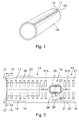
- Figure 1 shows a perspective view of a roll bent tubular member, denoted overall by reference number 10, having a longitudinal slot 11 delimited by flat side edges, not curved, denoted by reference numbers 12 and 13 respectively.
- the flat edges 12 and 13 of the tubular member are shaped by a subsequent rolling operation of the edges, which provides the tubular member 10 with a perfectly circular profile.
- the machine substantially comprises a supporting frame for a first conveyor 14 on the inlet side for the tubular member 10, a second conveyor 15 on the opposite or outlet side for the tubular member 10 formed, and a roll shaping device 16 for shaping the edges 12 and 13 of the tubular member 10, provided in an intermediate position between the two conveyors 14 and 15; the machine also comprises drive means for pushing or driving the tubular member 10 as described hereinunder.
- the two conveyors 14 and 15 can be of any suitable type; for example they can consist of two sets of slanted idle rollers 17 and 18, arranged in a V shape, or of powered rollers acting to move the tubular member 10 forwards, towards and through the roll shaping device 16 for shaping the edges of the tubular member 10, or to move it along the conveyors themselves.
- the V or slanted arrangement of the rollers also provides a suitable means for guiding and angular orientation of the tubular member 10.
- the drive means can consist, for example, of slides 19 moving along longitudinal guides 20 which extends on a respective side parallel to the longitudinal axis of the machine.
- Each slide 19 is provided with an arm 21 which engages against the rear edge of the tubular member 10 to push it and make it move forwards on the inlet conveyor 14 towards the shaping device 16, through the latter and on the outlet conveyor 15.
- Each slide 19 can be reciprocated in both directions along the guide 20 in any appropriate way, for example by providing a chain drive system, not shown, wherein the chains to drive the two slides 19 are connected to each other and synchronised by means of a mechanical shaft, an electric shaft or in any other suitable way.
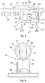
- the shaping device 16 as shown in Figures 2 and 3, and in particular in Figures 4 and 5, comprises a lower shaping member 25 and an upper shaping member 26, both capable of rotating around their own horizontal axis 27 and 28.
- the two axes 27 and 28 are arranged parallel one to the other, in a cross direction to the longitudinal axis of the shaping machine.
- One of the rollers for example the lower roller 25, is connected to a respective drive motor 29, not shown, and is supported in a fixed position by the frame 30 of the machine, while the other roller, or upper roller 26, is movably supported in a vertical direction in order to be moved towards and away from the lower roller 25.
- the movable roller 26 is supported to rotate idly by a frame 31 sliding in vertical guides 32.
- the frame 31 has a substantially rectangular shape and is formed by two flat cross sides 31A, and by two longitudinal sides 31B.
- the cross sides 31A have a reduced thickness in order to pass through the longitudinal slot 11 of the tubular member 10, in any case such as to resist the thrust which must be exerted in order to press the upper shaping roller 26 against the lower shaping roller 25 with the necessary pressure force for shaping the flat edges 12 and 13 of the tubular member 10, while the latter is made to move forwards through the same shaping device 16.
- the rising and lowering movement of the frame 31 with the upper shaping roller 26 and the necessary thrust of the roller 26 against the roller 25 can be obtained by any suitable drive means, for example by providing double-acting hydraulic cylinders 33 connected to the lower side 31B of the frame 31, as indicated schematically in Figure 3.
- the shaping device 16 comprises a lower shaping roller 25 in the form of a roller having a peripheral groove R1 of concave or circle arc profile in order to adapt against the external surface of the tubular member 10. It also comprises an upper shaping roller 26 of a convex profile, or barrel shaped, in order to adapt to the internal surface of the tubular member 10 to shape its flat edges 12 and 13 when they are clamped and tightly compressed between the two shaping rollers 25 and 26.
- the radii of curvature of both shaping rollers 25 and 26, may correspond one to the other or differ one from the other and from the radii of curvature of the internal and external surfaces of the tubular member 10.
- Figures 4 and 5 show conditions of equality between R1 and Re and respectively between R2 and Ri, and of coinciding of the curvature centres.
- the values of the radii of curvature of the shaping rollers 25 and 26, insofar as referred above can also differ from the nominal radii of curvature of the internal and external surfaces of the tubular member 10, according to the dimensions of the same tubular member, or the widths of the flat edges 12 and 13, the thickness of the metal sheet used to obtain the tubular member or other constructional and functional features of the same shaping machine.
- the upper roller 26 is raised or spaced from the lower roller 25 for a length greater than the thickness of the metal sheet of the tubular member 10, to allow its insertion between the two rollers.
- the slot 11 has to be maintained aligned with the longitudinal axis of the frame 31 supporting the upper roller 26 so that the two cross sides 31A of said frame 31 can pass through the slot 11. This can be achieved by adopting appropriate means for guiding and angular orientation of the tubular member 10.
- the driving of the tubular member 10 through the shaping device 16 may be performed in any way, for example by means of the lower shaping roller 25 driven by the appropriate electric motor 29, or by the previously described pushing device.
- the tubular member 10, with perfectly curved edges, coming from the shaping device 16, will continue its forward movement along the outlet conveyor 15 in order to be subsequently unloaded.
- a shaping device 16 which adapts to a wide range of diameters or radii of curvature, without being forced to change the shaping rollers 25 and 26 on each occasion.
- both the lower shaping member 25 and the upper shaping member 26 comprise a plurality of rolling elements 25A, 25B, 25N and 26A, 26B, 26N, angularly spaced along a theoretical circle arc, maintaining the axes of the rolling elements or their profiles tangent to the circles themselves.
- Each rolling element of the lower shaping member 25 and/or of the upper shaping member 26 is supported in a radially adjustable form in order to vary the reciprocal position or distance, and consequently to vary the radius of the theoretical arc of curvature along which the rolling members 25A-25N and 26A-26N are arranged respectively.
- the adjustment and support of the various rolling members may be performed in any appropriate way, for example as shown for the central rolling element 25B of the lower shaping member 25 in Figure 6.
- the rolling element 25B is idly rotating supported, by a slider 37 movable along lateral guides 38 attached to the frame 30 of the machine.
- the slider 37 has in its central piece 37', a threaded hole 39 wherein a threaded pin 40 is screwed and provided at its lower end with a cylindrical head 41 to rotate in a corresponding seating 42 of the support frame 30, in the manner shown.
- the threaded pin 40 has, in an intermediate position, a hexagonal head 43 whereon an operator can act with a wrench to vary the position of the slider 37 and consequently of the roller 25B.
- the rolling elements of the two shaping members 25 and 26 can have any position, and also any shape and dimensions, which will obviously have to adapt to the diameters of the pieces to be shaped. It is however advantageous for the lower shaping member 25 to have a central rolling element 25B positioned at the edges 12 and 13 to be bent which rest against the peripheral surface of said central rolling element 25B. This latter must preferably have a concave surface, formed by a peripheral groove, while the remaining rolling elements may have a convex shape, or a cylindrical shape of limited length, such as to rest against a narrow contact band with the internal and external surfaces of the tubular member 10.
- the invention is aimed at a method and a machine for shaping the straight longitudinal edges of roll bent pieces in order to eliminate the initial defect resulting from a previous bending phase, conferring the required roundness to said edges.
Landscapes
- Engineering & Computer Science (AREA)
- Mechanical Engineering (AREA)
- Bending Of Plates, Rods, And Pipes (AREA)
- Casting Or Compression Moulding Of Plastics Or The Like (AREA)
Applications Claiming Priority (2)
| Application Number | Priority Date | Filing Date | Title |
|---|---|---|---|
| ITMI972777 IT1296977B1 (it) | 1997-12-16 | 1997-12-16 | Procedimento e macchina per sagomare i bordi di pezzi calandrati |
| ITMI972777 | 1997-12-16 |
Publications (2)
| Publication Number | Publication Date |
|---|---|
| EP0924004A2 true EP0924004A2 (fr) | 1999-06-23 |
| EP0924004A3 EP0924004A3 (fr) | 2000-03-15 |
Family
ID=11378374
Family Applications (1)
| Application Number | Title | Priority Date | Filing Date |
|---|---|---|---|
| EP98123722A Withdrawn EP0924004A3 (fr) | 1997-12-16 | 1998-12-14 | Procédé et machine de formage de bords de pièces cintrées |
Country Status (2)
| Country | Link |
|---|---|
| EP (1) | EP0924004A3 (fr) |
| IT (1) | IT1296977B1 (fr) |
Cited By (1)
| Publication number | Priority date | Publication date | Assignee | Title |
|---|---|---|---|---|
| EP3243577B1 (fr) * | 2016-05-10 | 2020-02-19 | Fives Oto S.P.A. | Unité de formage pour une ligne de machines à profiler |
Family Cites Families (2)
| Publication number | Priority date | Publication date | Assignee | Title |
|---|---|---|---|---|
| DE588960C (de) * | 1931-10-04 | 1933-12-01 | Mannesmann Ag | Vorrichtung zum gleichzeitigen Rundbiegen der beiden geraden Blechstosskanten von auf Drei- oder Vierwalzenbiegemaschinen gebogenen Rohrschuessen |
| DE915932C (de) * | 1950-02-26 | 1954-08-02 | Linde Eismasch Ag | Vorrichtung zum kontinuierlichen Herstellen laengsnahtgeschweisster Rohre |
-
1997
- 1997-12-16 IT ITMI972777 patent/IT1296977B1/it active IP Right Grant
-
1998
- 1998-12-14 EP EP98123722A patent/EP0924004A3/fr not_active Withdrawn
Cited By (1)
| Publication number | Priority date | Publication date | Assignee | Title |
|---|---|---|---|---|
| EP3243577B1 (fr) * | 2016-05-10 | 2020-02-19 | Fives Oto S.P.A. | Unité de formage pour une ligne de machines à profiler |
Also Published As
| Publication number | Publication date |
|---|---|
| IT1296977B1 (it) | 1999-08-03 |
| EP0924004A3 (fr) | 2000-03-15 |
| ITMI972777A1 (it) | 1999-06-16 |
Similar Documents
| Publication | Publication Date | Title |
|---|---|---|
| US7337642B2 (en) | Roll-former apparatus with rapid-adjust sweep box | |
| US9192972B2 (en) | Forming method and forming device | |
| US5115658A (en) | Shaping machine for cylindrically bending a plate | |
| KR20110061620A (ko) | 가변 단면을 갖는 프로파일을 냉간 압연 성형하는 시스템 | |
| EP0733428B1 (fr) | Méthode et appareil pour couper et perforer des tubes | |
| CN112170533A (zh) | 通用型自动制管机 | |
| EP0924004A2 (fr) | Procédé et machine de formage de bords de pièces cintrées | |
| US3442108A (en) | Metal-handling method and apparatus | |
| US20110302982A1 (en) | Device for Forming Conical Sections | |
| CN117260283A (zh) | 一种长形导轨生产加工工艺 | |
| KR200461590Y1 (ko) | 관부재 단부 성형장치 | |
| KR20140017904A (ko) | 그라비아 인쇄롤러 제작용 강관 제조 장치 | |
| SU1207390A3 (ru) | Способ поперечной гибки профилированного или продольно-гофрированного листового металла и устройство дл его осуществлени | |
| CN213409867U (zh) | 通用型自动制管机 | |
| JP2002052450A (ja) | 縁取り装置 | |
| CN221231985U (zh) | 一种铜管矫直机 | |
| CN116571660B (zh) | 一种金属线材调直切割机 | |
| CN108747404B (zh) | 一种全自动滚刷支架成型机 | |
| US4112727A (en) | Method and apparatus for making pipe flanges | |
| CN114434268B (zh) | 一种鱼钩加工用成型设备 | |
| CN120306496B (zh) | 一种散热器边板冷弯成型自动化装备 | |
| CN2410057Y (zh) | 楔横轧轴类件辊压式矫直机 | |
| US3197991A (en) | Apparatus and method for tapering bars | |
| KR102855835B1 (ko) | 열교환기용 동파이프 가공장치 | |
| CN116329354B (zh) | 一种铝制型材加工用多角度折边装置 |
Legal Events
| Date | Code | Title | Description |
|---|---|---|---|
| PUAI | Public reference made under article 153(3) epc to a published international application that has entered the european phase |
Free format text: ORIGINAL CODE: 0009012 |
|
| AK | Designated contracting states |
Kind code of ref document: A2 Designated state(s): AT BE CH CY DE DK ES FI FR GB GR IE IT LI LU MC NL PT SE |
|
| AX | Request for extension of the european patent |
Free format text: AL;LT;LV;MK;RO;SI |
|
| PUAL | Search report despatched |
Free format text: ORIGINAL CODE: 0009013 |
|
| AK | Designated contracting states |
Kind code of ref document: A3 Designated state(s): AT BE CH CY DE DK ES FI FR GB GR IE IT LI LU MC NL PT SE |
|
| AX | Request for extension of the european patent |
Free format text: AL;LT;LV;MK;RO;SI |
|
| RIC1 | Information provided on ipc code assigned before grant |
Free format text: 7B 21C 37/06 A, 7B 21C 37/08 B, 7B 21D 5/12 B |
|
| AKX | Designation fees paid | ||
| STAA | Information on the status of an ep patent application or granted ep patent |
Free format text: STATUS: THE APPLICATION IS DEEMED TO BE WITHDRAWN |
|
| 18D | Application deemed to be withdrawn |
Effective date: 20000916 |
|
| REG | Reference to a national code |
Ref country code: DE Ref legal event code: 8566 |