EP0924053A2 - Elektro-Schweisseinrichtung - Google Patents
Elektro-Schweisseinrichtung Download PDFInfo
- Publication number
- EP0924053A2 EP0924053A2 EP98123250A EP98123250A EP0924053A2 EP 0924053 A2 EP0924053 A2 EP 0924053A2 EP 98123250 A EP98123250 A EP 98123250A EP 98123250 A EP98123250 A EP 98123250A EP 0924053 A2 EP0924053 A2 EP 0924053A2
- Authority
- EP
- European Patent Office
- Prior art keywords
- temperature
- welding
- welding device
- value
- preheating
- Prior art date
- Legal status (The legal status is an assumption and is not a legal conclusion. Google has not performed a legal analysis and makes no representation as to the accuracy of the status listed.)
- Granted
Links
- 238000003466 welding Methods 0.000 title claims abstract description 107
- 238000010438 heat treatment Methods 0.000 claims abstract description 43
- 230000001105 regulatory effect Effects 0.000 claims abstract description 6
- 238000000034 method Methods 0.000 claims description 14
- 238000002844 melting Methods 0.000 claims description 13
- 230000008018 melting Effects 0.000 claims description 13
- 239000000155 melt Substances 0.000 claims description 6
- 238000001514 detection method Methods 0.000 claims description 5
- 238000005259 measurement Methods 0.000 claims description 5
- 238000001816 cooling Methods 0.000 claims description 3
- 238000004861 thermometry Methods 0.000 claims description 2
- 230000000704 physical effect Effects 0.000 claims 1
- 238000004519 manufacturing process Methods 0.000 description 6
- 238000010586 diagram Methods 0.000 description 5
- 238000011161 development Methods 0.000 description 4
- 230000018109 developmental process Effects 0.000 description 4
- 230000003068 static effect Effects 0.000 description 4
- 238000012360 testing method Methods 0.000 description 4
- 230000007613 environmental effect Effects 0.000 description 3
- 238000003860 storage Methods 0.000 description 2
- 230000006978 adaptation Effects 0.000 description 1
- 238000012937 correction Methods 0.000 description 1
- 238000007791 dehumidification Methods 0.000 description 1
- 238000013461 design Methods 0.000 description 1
- 238000012552 review Methods 0.000 description 1
Images


Classifications
-
- B—PERFORMING OPERATIONS; TRANSPORTING
- B29—WORKING OF PLASTICS; WORKING OF SUBSTANCES IN A PLASTIC STATE IN GENERAL
- B29C—SHAPING OR JOINING OF PLASTICS; SHAPING OF MATERIAL IN A PLASTIC STATE, NOT OTHERWISE PROVIDED FOR; AFTER-TREATMENT OF THE SHAPED PRODUCTS, e.g. REPAIRING
- B29C65/00—Joining or sealing of preformed parts, e.g. welding of plastics materials; Apparatus therefor
- B29C65/02—Joining or sealing of preformed parts, e.g. welding of plastics materials; Apparatus therefor by heating, with or without pressure
- B29C65/34—Joining or sealing of preformed parts, e.g. welding of plastics materials; Apparatus therefor by heating, with or without pressure using heated elements which remain in the joint, e.g. "verlorenes Schweisselement"
- B29C65/3404—Joining or sealing of preformed parts, e.g. welding of plastics materials; Apparatus therefor by heating, with or without pressure using heated elements which remain in the joint, e.g. "verlorenes Schweisselement" characterised by the type of heated elements which remain in the joint
- B29C65/342—Joining or sealing of preformed parts, e.g. welding of plastics materials; Apparatus therefor by heating, with or without pressure using heated elements which remain in the joint, e.g. "verlorenes Schweisselement" characterised by the type of heated elements which remain in the joint comprising at least a single wire, e.g. in the form of a winding
-
- B—PERFORMING OPERATIONS; TRANSPORTING
- B29—WORKING OF PLASTICS; WORKING OF SUBSTANCES IN A PLASTIC STATE IN GENERAL
- B29C—SHAPING OR JOINING OF PLASTICS; SHAPING OF MATERIAL IN A PLASTIC STATE, NOT OTHERWISE PROVIDED FOR; AFTER-TREATMENT OF THE SHAPED PRODUCTS, e.g. REPAIRING
- B29C65/00—Joining or sealing of preformed parts, e.g. welding of plastics materials; Apparatus therefor
- B29C65/02—Joining or sealing of preformed parts, e.g. welding of plastics materials; Apparatus therefor by heating, with or without pressure
- B29C65/34—Joining or sealing of preformed parts, e.g. welding of plastics materials; Apparatus therefor by heating, with or without pressure using heated elements which remain in the joint, e.g. "verlorenes Schweisselement"
- B29C65/3472—Joining or sealing of preformed parts, e.g. welding of plastics materials; Apparatus therefor by heating, with or without pressure using heated elements which remain in the joint, e.g. "verlorenes Schweisselement" characterised by the composition of the heated elements which remain in the joint
- B29C65/3476—Joining or sealing of preformed parts, e.g. welding of plastics materials; Apparatus therefor by heating, with or without pressure using heated elements which remain in the joint, e.g. "verlorenes Schweisselement" characterised by the composition of the heated elements which remain in the joint being metallic
-
- B—PERFORMING OPERATIONS; TRANSPORTING
- B29—WORKING OF PLASTICS; WORKING OF SUBSTANCES IN A PLASTIC STATE IN GENERAL
- B29C—SHAPING OR JOINING OF PLASTICS; SHAPING OF MATERIAL IN A PLASTIC STATE, NOT OTHERWISE PROVIDED FOR; AFTER-TREATMENT OF THE SHAPED PRODUCTS, e.g. REPAIRING
- B29C66/00—General aspects of processes or apparatus for joining preformed parts
- B29C66/01—General aspects dealing with the joint area or with the area to be joined
- B29C66/02—Preparation of the material, in the area to be joined, prior to joining or welding
- B29C66/024—Thermal pre-treatments
- B29C66/0242—Heating, or preheating, e.g. drying
-
- B—PERFORMING OPERATIONS; TRANSPORTING
- B29—WORKING OF PLASTICS; WORKING OF SUBSTANCES IN A PLASTIC STATE IN GENERAL
- B29C—SHAPING OR JOINING OF PLASTICS; SHAPING OF MATERIAL IN A PLASTIC STATE, NOT OTHERWISE PROVIDED FOR; AFTER-TREATMENT OF THE SHAPED PRODUCTS, e.g. REPAIRING
- B29C66/00—General aspects of processes or apparatus for joining preformed parts
- B29C66/50—General aspects of joining tubular articles; General aspects of joining long products, i.e. bars or profiled elements; General aspects of joining single elements to tubular articles, hollow articles or bars; General aspects of joining several hollow-preforms to form hollow or tubular articles
- B29C66/51—Joining tubular articles, profiled elements or bars; Joining single elements to tubular articles, hollow articles or bars; Joining several hollow-preforms to form hollow or tubular articles
- B29C66/52—Joining tubular articles, bars or profiled elements
- B29C66/522—Joining tubular articles
- B29C66/5221—Joining tubular articles for forming coaxial connections, i.e. the tubular articles to be joined forming a zero angle relative to each other
-
- B—PERFORMING OPERATIONS; TRANSPORTING
- B29—WORKING OF PLASTICS; WORKING OF SUBSTANCES IN A PLASTIC STATE IN GENERAL
- B29C—SHAPING OR JOINING OF PLASTICS; SHAPING OF MATERIAL IN A PLASTIC STATE, NOT OTHERWISE PROVIDED FOR; AFTER-TREATMENT OF THE SHAPED PRODUCTS, e.g. REPAIRING
- B29C66/00—General aspects of processes or apparatus for joining preformed parts
- B29C66/50—General aspects of joining tubular articles; General aspects of joining long products, i.e. bars or profiled elements; General aspects of joining single elements to tubular articles, hollow articles or bars; General aspects of joining several hollow-preforms to form hollow or tubular articles
- B29C66/51—Joining tubular articles, profiled elements or bars; Joining single elements to tubular articles, hollow articles or bars; Joining several hollow-preforms to form hollow or tubular articles
- B29C66/52—Joining tubular articles, bars or profiled elements
- B29C66/522—Joining tubular articles
- B29C66/5229—Joining tubular articles involving the use of a socket
-
- B—PERFORMING OPERATIONS; TRANSPORTING
- B29—WORKING OF PLASTICS; WORKING OF SUBSTANCES IN A PLASTIC STATE IN GENERAL
- B29C—SHAPING OR JOINING OF PLASTICS; SHAPING OF MATERIAL IN A PLASTIC STATE, NOT OTHERWISE PROVIDED FOR; AFTER-TREATMENT OF THE SHAPED PRODUCTS, e.g. REPAIRING
- B29C66/00—General aspects of processes or apparatus for joining preformed parts
- B29C66/90—Measuring or controlling the joining process
- B29C66/91—Measuring or controlling the joining process by measuring or controlling the temperature, the heat or the thermal flux
- B29C66/912—Measuring or controlling the joining process by measuring or controlling the temperature, the heat or the thermal flux by measuring the temperature, the heat or the thermal flux
- B29C66/9121—Measuring or controlling the joining process by measuring or controlling the temperature, the heat or the thermal flux by measuring the temperature, the heat or the thermal flux by measuring the temperature
- B29C66/91221—Measuring or controlling the joining process by measuring or controlling the temperature, the heat or the thermal flux by measuring the temperature, the heat or the thermal flux by measuring the temperature of the parts to be joined
-
- B—PERFORMING OPERATIONS; TRANSPORTING
- B29—WORKING OF PLASTICS; WORKING OF SUBSTANCES IN A PLASTIC STATE IN GENERAL
- B29C—SHAPING OR JOINING OF PLASTICS; SHAPING OF MATERIAL IN A PLASTIC STATE, NOT OTHERWISE PROVIDED FOR; AFTER-TREATMENT OF THE SHAPED PRODUCTS, e.g. REPAIRING
- B29C66/00—General aspects of processes or apparatus for joining preformed parts
- B29C66/90—Measuring or controlling the joining process
- B29C66/91—Measuring or controlling the joining process by measuring or controlling the temperature, the heat or the thermal flux
- B29C66/912—Measuring or controlling the joining process by measuring or controlling the temperature, the heat or the thermal flux by measuring the temperature, the heat or the thermal flux
- B29C66/9131—Measuring or controlling the joining process by measuring or controlling the temperature, the heat or the thermal flux by measuring the temperature, the heat or the thermal flux by measuring the heat or the thermal flux, i.e. the heat flux
- B29C66/91311—Measuring or controlling the joining process by measuring or controlling the temperature, the heat or the thermal flux by measuring the temperature, the heat or the thermal flux by measuring the heat or the thermal flux, i.e. the heat flux by measuring the heat generated by Joule heating or induction heating
- B29C66/91313—Measuring or controlling the joining process by measuring or controlling the temperature, the heat or the thermal flux by measuring the temperature, the heat or the thermal flux by measuring the heat or the thermal flux, i.e. the heat flux by measuring the heat generated by Joule heating or induction heating by measuring the voltage, i.e. the electric potential difference or electric tension
-
- B—PERFORMING OPERATIONS; TRANSPORTING
- B29—WORKING OF PLASTICS; WORKING OF SUBSTANCES IN A PLASTIC STATE IN GENERAL
- B29C—SHAPING OR JOINING OF PLASTICS; SHAPING OF MATERIAL IN A PLASTIC STATE, NOT OTHERWISE PROVIDED FOR; AFTER-TREATMENT OF THE SHAPED PRODUCTS, e.g. REPAIRING
- B29C66/00—General aspects of processes or apparatus for joining preformed parts
- B29C66/90—Measuring or controlling the joining process
- B29C66/91—Measuring or controlling the joining process by measuring or controlling the temperature, the heat or the thermal flux
- B29C66/912—Measuring or controlling the joining process by measuring or controlling the temperature, the heat or the thermal flux by measuring the temperature, the heat or the thermal flux
- B29C66/9131—Measuring or controlling the joining process by measuring or controlling the temperature, the heat or the thermal flux by measuring the temperature, the heat or the thermal flux by measuring the heat or the thermal flux, i.e. the heat flux
- B29C66/91311—Measuring or controlling the joining process by measuring or controlling the temperature, the heat or the thermal flux by measuring the temperature, the heat or the thermal flux by measuring the heat or the thermal flux, i.e. the heat flux by measuring the heat generated by Joule heating or induction heating
- B29C66/91315—Measuring or controlling the joining process by measuring or controlling the temperature, the heat or the thermal flux by measuring the temperature, the heat or the thermal flux by measuring the heat or the thermal flux, i.e. the heat flux by measuring the heat generated by Joule heating or induction heating by measuring the current intensity
-
- B—PERFORMING OPERATIONS; TRANSPORTING
- B29—WORKING OF PLASTICS; WORKING OF SUBSTANCES IN A PLASTIC STATE IN GENERAL
- B29C—SHAPING OR JOINING OF PLASTICS; SHAPING OF MATERIAL IN A PLASTIC STATE, NOT OTHERWISE PROVIDED FOR; AFTER-TREATMENT OF THE SHAPED PRODUCTS, e.g. REPAIRING
- B29C66/00—General aspects of processes or apparatus for joining preformed parts
- B29C66/90—Measuring or controlling the joining process
- B29C66/91—Measuring or controlling the joining process by measuring or controlling the temperature, the heat or the thermal flux
- B29C66/912—Measuring or controlling the joining process by measuring or controlling the temperature, the heat or the thermal flux by measuring the temperature, the heat or the thermal flux
- B29C66/9131—Measuring or controlling the joining process by measuring or controlling the temperature, the heat or the thermal flux by measuring the temperature, the heat or the thermal flux by measuring the heat or the thermal flux, i.e. the heat flux
- B29C66/91311—Measuring or controlling the joining process by measuring or controlling the temperature, the heat or the thermal flux by measuring the temperature, the heat or the thermal flux by measuring the heat or the thermal flux, i.e. the heat flux by measuring the heat generated by Joule heating or induction heating
- B29C66/91317—Measuring or controlling the joining process by measuring or controlling the temperature, the heat or the thermal flux by measuring the temperature, the heat or the thermal flux by measuring the heat or the thermal flux, i.e. the heat flux by measuring the heat generated by Joule heating or induction heating by measuring the electrical resistance
-
- B—PERFORMING OPERATIONS; TRANSPORTING
- B29—WORKING OF PLASTICS; WORKING OF SUBSTANCES IN A PLASTIC STATE IN GENERAL
- B29C—SHAPING OR JOINING OF PLASTICS; SHAPING OF MATERIAL IN A PLASTIC STATE, NOT OTHERWISE PROVIDED FOR; AFTER-TREATMENT OF THE SHAPED PRODUCTS, e.g. REPAIRING
- B29C66/00—General aspects of processes or apparatus for joining preformed parts
- B29C66/90—Measuring or controlling the joining process
- B29C66/91—Measuring or controlling the joining process by measuring or controlling the temperature, the heat or the thermal flux
- B29C66/914—Measuring or controlling the joining process by measuring or controlling the temperature, the heat or the thermal flux by controlling or regulating the temperature, the heat or the thermal flux
- B29C66/9141—Measuring or controlling the joining process by measuring or controlling the temperature, the heat or the thermal flux by controlling or regulating the temperature, the heat or the thermal flux by controlling or regulating the temperature
- B29C66/91411—Measuring or controlling the joining process by measuring or controlling the temperature, the heat or the thermal flux by controlling or regulating the temperature, the heat or the thermal flux by controlling or regulating the temperature of the parts to be joined, e.g. the joining process taking the temperature of the parts to be joined into account
-
- B—PERFORMING OPERATIONS; TRANSPORTING
- B29—WORKING OF PLASTICS; WORKING OF SUBSTANCES IN A PLASTIC STATE IN GENERAL
- B29C—SHAPING OR JOINING OF PLASTICS; SHAPING OF MATERIAL IN A PLASTIC STATE, NOT OTHERWISE PROVIDED FOR; AFTER-TREATMENT OF THE SHAPED PRODUCTS, e.g. REPAIRING
- B29C66/00—General aspects of processes or apparatus for joining preformed parts
- B29C66/90—Measuring or controlling the joining process
- B29C66/91—Measuring or controlling the joining process by measuring or controlling the temperature, the heat or the thermal flux
- B29C66/914—Measuring or controlling the joining process by measuring or controlling the temperature, the heat or the thermal flux by controlling or regulating the temperature, the heat or the thermal flux
- B29C66/9141—Measuring or controlling the joining process by measuring or controlling the temperature, the heat or the thermal flux by controlling or regulating the temperature, the heat or the thermal flux by controlling or regulating the temperature
- B29C66/91441—Measuring or controlling the joining process by measuring or controlling the temperature, the heat or the thermal flux by controlling or regulating the temperature, the heat or the thermal flux by controlling or regulating the temperature the temperature being non-constant over time
- B29C66/91443—Measuring or controlling the joining process by measuring or controlling the temperature, the heat or the thermal flux by controlling or regulating the temperature, the heat or the thermal flux by controlling or regulating the temperature the temperature being non-constant over time following a temperature-time profile
-
- B—PERFORMING OPERATIONS; TRANSPORTING
- B29—WORKING OF PLASTICS; WORKING OF SUBSTANCES IN A PLASTIC STATE IN GENERAL
- B29C—SHAPING OR JOINING OF PLASTICS; SHAPING OF MATERIAL IN A PLASTIC STATE, NOT OTHERWISE PROVIDED FOR; AFTER-TREATMENT OF THE SHAPED PRODUCTS, e.g. REPAIRING
- B29C66/00—General aspects of processes or apparatus for joining preformed parts
- B29C66/90—Measuring or controlling the joining process
- B29C66/91—Measuring or controlling the joining process by measuring or controlling the temperature, the heat or the thermal flux
- B29C66/914—Measuring or controlling the joining process by measuring or controlling the temperature, the heat or the thermal flux by controlling or regulating the temperature, the heat or the thermal flux
- B29C66/9141—Measuring or controlling the joining process by measuring or controlling the temperature, the heat or the thermal flux by controlling or regulating the temperature, the heat or the thermal flux by controlling or regulating the temperature
- B29C66/91441—Measuring or controlling the joining process by measuring or controlling the temperature, the heat or the thermal flux by controlling or regulating the temperature, the heat or the thermal flux by controlling or regulating the temperature the temperature being non-constant over time
- B29C66/91443—Measuring or controlling the joining process by measuring or controlling the temperature, the heat or the thermal flux by controlling or regulating the temperature, the heat or the thermal flux by controlling or regulating the temperature the temperature being non-constant over time following a temperature-time profile
- B29C66/91445—Measuring or controlling the joining process by measuring or controlling the temperature, the heat or the thermal flux by controlling or regulating the temperature, the heat or the thermal flux by controlling or regulating the temperature the temperature being non-constant over time following a temperature-time profile by steps
-
- B—PERFORMING OPERATIONS; TRANSPORTING
- B29—WORKING OF PLASTICS; WORKING OF SUBSTANCES IN A PLASTIC STATE IN GENERAL
- B29C—SHAPING OR JOINING OF PLASTICS; SHAPING OF MATERIAL IN A PLASTIC STATE, NOT OTHERWISE PROVIDED FOR; AFTER-TREATMENT OF THE SHAPED PRODUCTS, e.g. REPAIRING
- B29C66/00—General aspects of processes or apparatus for joining preformed parts
- B29C66/90—Measuring or controlling the joining process
- B29C66/91—Measuring or controlling the joining process by measuring or controlling the temperature, the heat or the thermal flux
- B29C66/914—Measuring or controlling the joining process by measuring or controlling the temperature, the heat or the thermal flux by controlling or regulating the temperature, the heat or the thermal flux
- B29C66/9161—Measuring or controlling the joining process by measuring or controlling the temperature, the heat or the thermal flux by controlling or regulating the temperature, the heat or the thermal flux by controlling or regulating the heat or the thermal flux, i.e. the heat flux
- B29C66/91651—Measuring or controlling the joining process by measuring or controlling the temperature, the heat or the thermal flux by controlling or regulating the temperature, the heat or the thermal flux by controlling or regulating the heat or the thermal flux, i.e. the heat flux by controlling or regulating the heat generated by Joule heating or induction heating
- B29C66/91653—Measuring or controlling the joining process by measuring or controlling the temperature, the heat or the thermal flux by controlling or regulating the temperature, the heat or the thermal flux by controlling or regulating the heat or the thermal flux, i.e. the heat flux by controlling or regulating the heat generated by Joule heating or induction heating by controlling or regulating the voltage, i.e. the electric potential difference or electric tension
-
- B—PERFORMING OPERATIONS; TRANSPORTING
- B29—WORKING OF PLASTICS; WORKING OF SUBSTANCES IN A PLASTIC STATE IN GENERAL
- B29C—SHAPING OR JOINING OF PLASTICS; SHAPING OF MATERIAL IN A PLASTIC STATE, NOT OTHERWISE PROVIDED FOR; AFTER-TREATMENT OF THE SHAPED PRODUCTS, e.g. REPAIRING
- B29C66/00—General aspects of processes or apparatus for joining preformed parts
- B29C66/90—Measuring or controlling the joining process
- B29C66/91—Measuring or controlling the joining process by measuring or controlling the temperature, the heat or the thermal flux
- B29C66/914—Measuring or controlling the joining process by measuring or controlling the temperature, the heat or the thermal flux by controlling or regulating the temperature, the heat or the thermal flux
- B29C66/9161—Measuring or controlling the joining process by measuring or controlling the temperature, the heat or the thermal flux by controlling or regulating the temperature, the heat or the thermal flux by controlling or regulating the heat or the thermal flux, i.e. the heat flux
- B29C66/91651—Measuring or controlling the joining process by measuring or controlling the temperature, the heat or the thermal flux by controlling or regulating the temperature, the heat or the thermal flux by controlling or regulating the heat or the thermal flux, i.e. the heat flux by controlling or regulating the heat generated by Joule heating or induction heating
- B29C66/91655—Measuring or controlling the joining process by measuring or controlling the temperature, the heat or the thermal flux by controlling or regulating the temperature, the heat or the thermal flux by controlling or regulating the heat or the thermal flux, i.e. the heat flux by controlling or regulating the heat generated by Joule heating or induction heating by controlling or regulating the current intensity
-
- B—PERFORMING OPERATIONS; TRANSPORTING
- B29—WORKING OF PLASTICS; WORKING OF SUBSTANCES IN A PLASTIC STATE IN GENERAL
- B29C—SHAPING OR JOINING OF PLASTICS; SHAPING OF MATERIAL IN A PLASTIC STATE, NOT OTHERWISE PROVIDED FOR; AFTER-TREATMENT OF THE SHAPED PRODUCTS, e.g. REPAIRING
- B29C66/00—General aspects of processes or apparatus for joining preformed parts
- B29C66/90—Measuring or controlling the joining process
- B29C66/91—Measuring or controlling the joining process by measuring or controlling the temperature, the heat or the thermal flux
- B29C66/919—Measuring or controlling the joining process by measuring or controlling the temperature, the heat or the thermal flux characterised by specific temperature, heat or thermal flux values or ranges
- B29C66/9192—Measuring or controlling the joining process by measuring or controlling the temperature, the heat or the thermal flux characterised by specific temperature, heat or thermal flux values or ranges in explicit relation to another variable, e.g. temperature diagrams
- B29C66/91951—Measuring or controlling the joining process by measuring or controlling the temperature, the heat or the thermal flux characterised by specific temperature, heat or thermal flux values or ranges in explicit relation to another variable, e.g. temperature diagrams in explicit relation to time, e.g. temperature-time diagrams
-
- B—PERFORMING OPERATIONS; TRANSPORTING
- B29—WORKING OF PLASTICS; WORKING OF SUBSTANCES IN A PLASTIC STATE IN GENERAL
- B29C—SHAPING OR JOINING OF PLASTICS; SHAPING OF MATERIAL IN A PLASTIC STATE, NOT OTHERWISE PROVIDED FOR; AFTER-TREATMENT OF THE SHAPED PRODUCTS, e.g. REPAIRING
- B29C66/00—General aspects of processes or apparatus for joining preformed parts
- B29C66/90—Measuring or controlling the joining process
- B29C66/96—Measuring or controlling the joining process characterised by the method for implementing the controlling of the joining process
- B29C66/961—Measuring or controlling the joining process characterised by the method for implementing the controlling of the joining process involving a feedback loop mechanism, e.g. comparison with a desired value
-
- B—PERFORMING OPERATIONS; TRANSPORTING
- B29—WORKING OF PLASTICS; WORKING OF SUBSTANCES IN A PLASTIC STATE IN GENERAL
- B29C—SHAPING OR JOINING OF PLASTICS; SHAPING OF MATERIAL IN A PLASTIC STATE, NOT OTHERWISE PROVIDED FOR; AFTER-TREATMENT OF THE SHAPED PRODUCTS, e.g. REPAIRING
- B29C66/00—General aspects of processes or apparatus for joining preformed parts
- B29C66/90—Measuring or controlling the joining process
- B29C66/96—Measuring or controlling the joining process characterised by the method for implementing the controlling of the joining process
- B29C66/967—Measuring or controlling the joining process characterised by the method for implementing the controlling of the joining process involving special data inputs or special data outputs, e.g. for monitoring purposes
- B29C66/9672—Measuring or controlling the joining process characterised by the method for implementing the controlling of the joining process involving special data inputs or special data outputs, e.g. for monitoring purposes involving special data inputs, e.g. involving barcodes, RFID tags
-
- B—PERFORMING OPERATIONS; TRANSPORTING
- B29—WORKING OF PLASTICS; WORKING OF SUBSTANCES IN A PLASTIC STATE IN GENERAL
- B29C—SHAPING OR JOINING OF PLASTICS; SHAPING OF MATERIAL IN A PLASTIC STATE, NOT OTHERWISE PROVIDED FOR; AFTER-TREATMENT OF THE SHAPED PRODUCTS, e.g. REPAIRING
- B29C66/00—General aspects of processes or apparatus for joining preformed parts
- B29C66/01—General aspects dealing with the joint area or with the area to be joined
- B29C66/05—Particular design of joint configurations
- B29C66/10—Particular design of joint configurations particular design of the joint cross-sections
- B29C66/11—Joint cross-sections comprising a single joint-segment, i.e. one of the parts to be joined comprising a single joint-segment in the joint cross-section
- B29C66/112—Single lapped joints
- B29C66/1122—Single lap to lap joints, i.e. overlap joints
-
- B—PERFORMING OPERATIONS; TRANSPORTING
- B29—WORKING OF PLASTICS; WORKING OF SUBSTANCES IN A PLASTIC STATE IN GENERAL
- B29C—SHAPING OR JOINING OF PLASTICS; SHAPING OF MATERIAL IN A PLASTIC STATE, NOT OTHERWISE PROVIDED FOR; AFTER-TREATMENT OF THE SHAPED PRODUCTS, e.g. REPAIRING
- B29C66/00—General aspects of processes or apparatus for joining preformed parts
- B29C66/90—Measuring or controlling the joining process
- B29C66/91—Measuring or controlling the joining process by measuring or controlling the temperature, the heat or the thermal flux
- B29C66/919—Measuring or controlling the joining process by measuring or controlling the temperature, the heat or the thermal flux characterised by specific temperature, heat or thermal flux values or ranges
-
- B—PERFORMING OPERATIONS; TRANSPORTING
- B29—WORKING OF PLASTICS; WORKING OF SUBSTANCES IN A PLASTIC STATE IN GENERAL
- B29C—SHAPING OR JOINING OF PLASTICS; SHAPING OF MATERIAL IN A PLASTIC STATE, NOT OTHERWISE PROVIDED FOR; AFTER-TREATMENT OF THE SHAPED PRODUCTS, e.g. REPAIRING
- B29C66/00—General aspects of processes or apparatus for joining preformed parts
- B29C66/90—Measuring or controlling the joining process
- B29C66/91—Measuring or controlling the joining process by measuring or controlling the temperature, the heat or the thermal flux
- B29C66/919—Measuring or controlling the joining process by measuring or controlling the temperature, the heat or the thermal flux characterised by specific temperature, heat or thermal flux values or ranges
- B29C66/9192—Measuring or controlling the joining process by measuring or controlling the temperature, the heat or the thermal flux characterised by specific temperature, heat or thermal flux values or ranges in explicit relation to another variable, e.g. temperature diagrams
- B29C66/91921—Measuring or controlling the joining process by measuring or controlling the temperature, the heat or the thermal flux characterised by specific temperature, heat or thermal flux values or ranges in explicit relation to another variable, e.g. temperature diagrams in explicit relation to another temperature, e.g. to the softening temperature or softening point, to the thermal degradation temperature or to the ambient temperature
-
- B—PERFORMING OPERATIONS; TRANSPORTING
- B29—WORKING OF PLASTICS; WORKING OF SUBSTANCES IN A PLASTIC STATE IN GENERAL
- B29C—SHAPING OR JOINING OF PLASTICS; SHAPING OF MATERIAL IN A PLASTIC STATE, NOT OTHERWISE PROVIDED FOR; AFTER-TREATMENT OF THE SHAPED PRODUCTS, e.g. REPAIRING
- B29C66/00—General aspects of processes or apparatus for joining preformed parts
- B29C66/90—Measuring or controlling the joining process
- B29C66/94—Measuring or controlling the joining process by measuring or controlling the time
- B29C66/944—Measuring or controlling the joining process by measuring or controlling the time by controlling or regulating the time
-
- B—PERFORMING OPERATIONS; TRANSPORTING
- B29—WORKING OF PLASTICS; WORKING OF SUBSTANCES IN A PLASTIC STATE IN GENERAL
- B29C—SHAPING OR JOINING OF PLASTICS; SHAPING OF MATERIAL IN A PLASTIC STATE, NOT OTHERWISE PROVIDED FOR; AFTER-TREATMENT OF THE SHAPED PRODUCTS, e.g. REPAIRING
- B29C66/00—General aspects of processes or apparatus for joining preformed parts
- B29C66/90—Measuring or controlling the joining process
- B29C66/95—Measuring or controlling the joining process by measuring or controlling specific variables not covered by groups B29C66/91 - B29C66/94
- B29C66/959—Measuring or controlling the joining process by measuring or controlling specific variables not covered by groups B29C66/91 - B29C66/94 characterised by specific values or ranges of said specific variables
- B29C66/9592—Measuring or controlling the joining process by measuring or controlling specific variables not covered by groups B29C66/91 - B29C66/94 characterised by specific values or ranges of said specific variables in explicit relation to another variable, e.g. X-Y diagrams
-
- B—PERFORMING OPERATIONS; TRANSPORTING
- B29—WORKING OF PLASTICS; WORKING OF SUBSTANCES IN A PLASTIC STATE IN GENERAL
- B29C—SHAPING OR JOINING OF PLASTICS; SHAPING OF MATERIAL IN A PLASTIC STATE, NOT OTHERWISE PROVIDED FOR; AFTER-TREATMENT OF THE SHAPED PRODUCTS, e.g. REPAIRING
- B29C66/00—General aspects of processes or apparatus for joining preformed parts
- B29C66/90—Measuring or controlling the joining process
- B29C66/96—Measuring or controlling the joining process characterised by the method for implementing the controlling of the joining process
- B29C66/962—Measuring or controlling the joining process characterised by the method for implementing the controlling of the joining process using proportional controllers, e.g. PID controllers [proportional–integral–derivative controllers]
-
- B—PERFORMING OPERATIONS; TRANSPORTING
- B29—WORKING OF PLASTICS; WORKING OF SUBSTANCES IN A PLASTIC STATE IN GENERAL
- B29C—SHAPING OR JOINING OF PLASTICS; SHAPING OF MATERIAL IN A PLASTIC STATE, NOT OTHERWISE PROVIDED FOR; AFTER-TREATMENT OF THE SHAPED PRODUCTS, e.g. REPAIRING
- B29C66/00—General aspects of processes or apparatus for joining preformed parts
- B29C66/90—Measuring or controlling the joining process
- B29C66/96—Measuring or controlling the joining process characterised by the method for implementing the controlling of the joining process
- B29C66/966—Measuring or controlling the joining process characterised by the method for implementing the controlling of the joining process using fuzzy logic
Definitions
- the invention relates to an electrical welding device for fittings and pipes according to the features specified in the preamble of claim 1.
- Such a welding device is known from PCT application WO 97/20682 automatic welding of heating coil fittings made of plastic known, their data are stored on a data carrier.
- the welding power supply to the heating coil is based on the data read from the data carrier and taking into account the Ambient temperature controlled.
- the heating coil is given during a Preheating and dehumidification duration with a preheating output and on brought increased temperature compared to the ambient temperature at which the Plastic is not yet plasticized.
- the preheating performance is compared to the welding performance reduced, which is supplied after the preheating and dehumidifying time becomes.
- the welding power is controlled according to the data on the data carrier, where correction factors such as the ambient temperature for varying the Welding time are taken into account.
- the data stored on the data carrier or Parameters are predetermined values, which are based on experience in practice, the actual values of the respective fittings, in particular as a result of manufacturing tolerances Subject to fluctuations. So is the resistance of the heating coil or the heating wire not only depends on its metallurgical composition, but also on the wire diameter and the total length, whereby for series production more or less large fluctuation ranges must be taken into account. By such fluctuations or changes, be it the fitting or the boundary conditions of the welding process, there are difficulties with reproducibility the welding results of the respective fittings and ultimately the Weld quality.
- the object of the invention is the welding device of the type mentioned to the extent that the weld quality of the welded joint is improved and the influence of tolerances or environmental conditions is reduced to a minimum.
- the electric welding device is supposed to require little production effort and a high one with optimized economy To enable appropriate welding requirements to be met.
- the proposed electric welding device according to the invention enables with little Effort and a high level of functional reliability in the production of a welded joint between fitting, pipe or the like.
- the electric welding device according to the invention is equally suitable for connecting a pipe with a fitting as for Connection of a molded body with another molded body, the direct connection of two pipes, the connection of a shaped body with a pipe or for connection of other components made of weldable plastic.
- the heating wire can also be part of a be separate building body, with the help of the fitting, the molded body, the pipe or the like are to be connected.
- the welding process is permanently monitored in the welding zone, with manufacturing tolerances and / or changes in the environmental conditions on the welding process themselves have no further influence. There is an optimal adaptation to the environmental conditions, so that a weld at extreme ambient temperatures is possible without, for example, temperature compensation based on empirical values is required.
- the converted or directly recorded temperature of the The melting zone is processed in the control unit of the welding machine and by means of the Control unit, the manipulated variable is controlled in such a way that at any time during the welding process the temperature of the melting zone ensures optimal welding is.
- control variable via the control unit.
- control variables to achieve and / or specifying an optimal welding temperature voltage, current, Power or energy can be specified.
- the control variable During the measuring and computing cycle of the Control loop and the acquisition of the actual temperature value becomes the control variable if necessary kept constant or switched on and off at intervals.
- a controller system is used that enables and multitasking for example, has a microprocessor, microcontroller or integrated computer. With multitasking, the fitting or the heating element is set to a fixed one Temperature warms up, and in further tasks or work cycles the temperature measured or calculated, security checks carried out and the resulting resulting control variable adjusted.
- An additional sensor system can be used to check whether it is within a defined melting zone distance the temperature of the melting zone reaches a predetermined threshold Has.
- the sensors mentioned can also be used to define the welding process switch off.
- the relevant parameters within the scope of the invention records and archives the welding process, in particular the welding temperature, the final welding temperature, the welding temperature profile, the preheating time as well as measurement results about a possible turn short.
- the welding device contains suitable means for this, such as memory elements, connection options for a printer or the like.
- the one that is preferably integrated into the welding machine Control unit can be a classic controller, such as a PDI controller, or by means of Fuzzy logic can be implemented.
- the actual temperature value of the fitting or the like is preferably recorded by means of physical wire properties or a melt pressure sensor system or magnetic high-frequency properties, in particular of the fitting, or the Noise thermometry or thermal noise. Furthermore, within the scope of the invention the cooling times of the welded fittings, molded body or the like exactly be specified. In view of lower manufacturing costs, larger ones Tolerances of the resistance of the heating wire are permitted. Furthermore enables the recording of the actual value of the temperature without any special additional effort logging the welding temperature.
- the temperature setpoint On the data carrier or storage element of the fitting, molded body or the like is the temperature setpoint and expediently the temperature coefficient of Heating wire saved. Furthermore, temperature values for preheating or of the entire welding process, for example also the Cooling phase after welding can be checked. Are on the disk furthermore the times for the welding and possibly the preheating are saved. For example, if the welding temperature reaches the specified setpoint, then the temperature during the saved welding time read from the data carrier of the heating element or fitting regulated in the required manner.
- the heating wire or the heating element is used in a special embodiment of the Invention not only for heating when current is applied to achieve the Welding temperature, but at the same time to implement the temperature detection, in particular by utilizing the physical wire properties.
- welding is first carried out by means of a temperature sensor Temperature of the heating element is detected.
- the following is the physical Wire properties, especially taking into account the temperature coefficient, a normalized resistance, especially of 20 ° C.
- the fitting 2 is via a cable 4 with an electric welding machine 6 connected, which contains a control unit 8. With the fitting 2 is also a Coupled data carrier 10, the stored data thereof by means of a reading unit 12 can be read and fed to the welding machine.
- the disk 10, which in particular designed as a bar code and fixed on the outer surface of the fitting 2 is arranged contains the specific data or parameters which are to be influenced the welding process in the electric welding device 6 and in particular the control unit 8 be taken into account.
- the fitting 2 contains a heating wire 14, and in a known manner in the form of a heating coil, through which for welding in a known manner Welding current flows.
- the fitting 2 is a sleeve for welding Tube ends formed, but the fitting 2 can also be within the scope of the invention Armature, saddle or the like may be formed, which on the tube outside attached and connected to it by welding.
- a temperature sensor 16 is also provided, which is preferably used to detect the Initial temperature of the heating wire 14 at the start of the weld and if necessary before preheating the fitting.
- the one with the temperature sensor 16 The detected initial temperature is according to block 18 in the welding device 6 for the computing unit 20 held ready, which is provided for calculating the wire temperature.
- the welding device can have a temperature sensor contain.
- a measuring unit 22 is provided, by means of which the welding voltage, the welding current and the resistance of the heating wire 14 of the fitting 2 are measurable.
- the welding device 6 contains power electronics 24, by means of which in a voltage-controlled temperature control the welding voltage can be specified. It should be noted that the power electronics in a current control is designed accordingly.
- the fitting-specific detected by the reading unit 12 Data is just like the wire temperature, i.e. the actual temperature value Control unit 8 supplied, which includes a computer as well as a memory. How indicated by block 26, the setpoint / actual value comparison takes place in the control unit 8 Heating wire temperature.
- a test unit according to block 28 also carries out a test Control, as well as security check and determining whether, if applicable Short turn is present.
- the temperature coefficient of the heating wire 14 is in the frame of the invention stored on the data carrier 10. Furthermore are on the disk 10 the setpoint of the welding temperature and possibly also the preheating temperature saved.
- the data carrier can also have 10 values corresponding to the ohmic resistance of the heating wire 14, the welding time and the preheating time included.
- a temperature sensor 30 for detecting the Melting temperature of the fitting 2 may be provided. By means of sensors or Temperature sensor 30 is checked whether at a defined distance from the Melting zone the temperature of the heating wire and thus the melt a predetermined Has reached the threshold value. According to block 32, the directly recorded temperature of the fitting or the melt of the control unit 8 is supplied in order to predetermined temperature setpoint via the manipulated variable, during welding and to regulate the fitting or melting temperature if necessary. Finally, the temperature sensor system explained can be used to switch off the Welding process can be used.
- the one implemented according to block 20 or according to block 32 via the temperature sensor 30 directly recorded temperature of the melting zone is the actual temperature of the control unit 8 regulated for temperature control according to the temperature setpoint.
- the Welding machine and in particular its control unit 8 is expediently of this type trained that the fitting 2 to the fixed predetermined temperature by multitasking is heated while the temperature is measured or calculated in other tasks, Security checks carried out and the resulting control variable adjusted become. It should be noted at this point that as control variables to achieve an optimal welding temperature voltage, current, power and energy can be provided. Furthermore, within the scope of the invention during the measurement and Computation cycle of the control loop and the acquisition of the actual temperature value respective control variable kept constant or switched on and off at intervals become.
- Corresponding signals 34 are sent from the control unit 8 to the power electronics 24 given.
- the signal 34 of the specification of a voltage value In the case of a voltage-controlled temperature control the signal 34 of the specification of a voltage value.
- a signal 36 becomes corresponding the welding duration or the end of the welding time to the power electronics 24 given.
- the preheating is expediently integrated into the invention Control procedures.
- at least two different temperature values specified, in particular a first value for preheating, for example 90 ° C. and also a second value for the welding temperature, for example of 220 ° C.
- the the first value for the preheating is specified in a particularly expedient manner, that an air gap between the inner surface of the fitting 2 and the outer surface of the pipe is bridged.
- the connecting element can be used even in extreme Ambient temperatures are welded reliably. This applies equally for low temperatures, for example for ambient temperatures ⁇ 0 °, as well for temperatures of 40 ° or above.
- the detection can be carried out within the scope of the invention with active preheating or sensing the closure or bridging of the air gap. This is carried out in particular by checking the supplied energy, power or Current during temperature control. It was recognized that during preheating due to the temperature control to a constant temperature of, for example 80 ° C by checking the course of energy, power or current a significant change in the checked value when the air gap is closed occurs, so that afterwards the actual welding starting from optimal and from initial conditions largely independent of the boundary conditions can be.
- the preheating without Sensing of a closure of the air gap take place, specifically by predetermined Preheating times. The preheating times are fixed and in expediently stored on the data carrier 10. Preheating is preferred depending on the dimension of the fitting and / or the preheating temperature given.
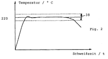
- the electric welding device regulates the temperature of the fitting and in particular the melt, for example, to a constant temperature of 220 ° C.
- a dynamic or static Short circuit can be detected.
- the temperature profile is recorded and at least temporarily saved to the reviews and controls with the to enable the respective current value.
- a tolerance band 38 is expedient Target welding temperature is specified and when leaving this tolerance band the control process is frozen.
- the control variable kept constant, such as the welding voltage, the further course of the temperature of the Fittings or the heating wire checked. If the temperature remains outside the tolerance, can after a predetermined time for a static turn, an interruption or a poor contact resistance, especially from the welding cable 4 are concluded on the heating wire 14 or the heating element of the fitting.
- the welding process is then started, in the case of a voltage-controlled temperature control by applying a constant welding voltage.
- the instantaneous value R th of the resistance is measured, either directly or by detecting the voltage or the current.
- the calculated temperature t of the fitting wire is fed to the control unit 8 for comparison as to whether or not the predetermined first target temperature of, for example, 240 ° C. has been reached. If the target temperature is not reached, the fitting is heated in accordance with N (i.e. no) as a result of the active regulation via the constant voltage present. When the first temperature setpoint is reached or exceeded, the voltage is regulated according to J (i.e. yes). The instantaneous value R th of the resistance is measured continuously and the actual temperature value is determined. In the context of the invention, this is carried out with an increased voltage until a second temperature setpoint, in this exemplary embodiment of 249 °, has not yet been exceeded.
- this second temperature setpoint is exceeded, that is to say the actual temperature value is no longer less than the second temperature setpoint or 249 °, the voltage supply no longer takes place via an increased value.
- a third temperature setpoint which according to the exemplary embodiment is set at 251 ° C., the welding voltage is reduced.
Landscapes
- Engineering & Computer Science (AREA)
- Mechanical Engineering (AREA)
- Physics & Mathematics (AREA)
- Thermal Sciences (AREA)
- Lining Or Joining Of Plastics Or The Like (AREA)
- Arc Welding Control (AREA)
- Resistance Welding (AREA)
- Branch Pipes, Bends, And The Like (AREA)
- Pressure Welding/Diffusion-Bonding (AREA)
Abstract
Description
- Fig. 1
- ein Blockschaltbild der Schweißeinrichtung,
- Fig. 2
- ein Temperaturdiagramm einer Schweißung,
- Fig. 3
- ein Flußdiagramm.
- 2
- Fitting
- 4
- Kabel
- 6
- Elektro-Schweißgerät
- 8
- Regeleinheit
- 10
- Datenträger
- 12
- Leseeinheit
- 14
- Heizdraht
- 16
- Temperatursensor
- 18
- Block / Temperatursensor
- 20
- Recheneinheit
- 22
- Meßeinheit
- 24
- Leistungselektronik
- 26
- Block / Soll-Istwert-Vergleich
- 28
- Block / Prüfeinheit
- 30
- Temperatursensor
- 32
- Block / Schmelztemperatur
- 34, 36
- Signal
- 38
- Toleranzband
Claims (11)
- Elektro-Schweißeinrichtung, insbesondere für Fittings (2) und Rohre aus Kunststoff, wobei ein mit Strom beaufschlagbarer Heizdraht (14) zur Erwärmung des zu verschweißenden Kunststoffs vorgesehen ist, enthaltend einen Datenträger (10), eine Regeleinheit (8) sowie insbesondere eine Vorrichtung zur Erfassung eines Temperaturwertes entsprechend der Temperatur der Schweißzone,
dadurch gekennzeichnet, daß der Temperaturwert der Regeleinheit (8) als Istwert zugeführt wird und daß ein Temperatur-Sollwert derart vorgegeben ist, daß über eine Stellgröße die Schweißzone auf die vorgegebene Temperatur der optimalen Verschweißung geregelt wird. - Schweißeinrichtung, insbesondere nach Anspruch 1, dadurch gekennzeichnet, daß im Datenträger (10) des Fittings (2) der Temperatur-Sollwert gespeichert ist und / oder daß der Temperatur-Sollwert für eine Vorwärmung und ein weiterer Sollwert für die Schweißung gespeichert ist und/oder daß der zeitliche Verlauf des Temperatur-Sollwerts gespeichert ist.
- Schweißeinrichtung nach Anspruch 1 oder 2, dadurch gekennzeichnet, daß für den oder die Temperatur-Sollwerte ein Toleranzband vorgegeben ist.
- Schweißeinrichtung nach einem der Ansprüche 1 bis 3, dadurch gekennzeichnet, daß derTemperatur-Istwert aufgrund physikalischer Eigenschaften des Heizdrahtes (14), oder einer Schmelzdrucksensorik oder magnetischer, insbesondere hochfrequenter Eigenschaften oder gemäß der Rauschthermometrie oder thermischen Rauschens erfaßt wird und/oder daß insbesondere der zeitliche Verlauf des Temperatur-Istwerts gespeichert wird.
- Schweißeinrichtung nach einem der Ansprüche 1 bis 4, dadurch gekennzeichnet, daß die Regeleinheit (8) für Multitasking ausgelegt ist, wobei zum einen die Erwärmung auf die fest vorgegebene Soll-Temperatur erfolgt, zum anderen die Temperatur gemessen und / oder errechnet wird, ferner Sicherheitsprüfungen durchgeführt und schließlich die resultierende Steuergröße nachgeregelt werden.
- Schweißeinrichtung nach einem der Ansprüche 1 bis 5, dadurch gekennzeichnet, daß das Fitting (2), insbesondere dessen Datenträger (10), fest vorgegebene Regelparameter enthält, insbesondere die Schweißtemperatur und / oder die Vorwärmtemperatur und / oder den Temperaturkoeffizienten des Heizdrahtes und / oder eine Angabe zur Vorwärmung erfolgt oder nicht und / oder die Zeiten für die Schweißung und gegebenenfalls für die Vorwärmung.
- Schweißeinrichtung nach einem der Ansprüche 1 bis 6, dadurch gekennzeichnet, daß während des Meß- und Regelzyklus des Regelkreises und der Erfassung des Istwertes der Temperatur die Steuergröße konstant gehalten wird oder aber intervallmäßig ab- und zugeschaltet wird.
- Schweißeinrichtung, insbesondere nach einem der Ansprüche 1 bis 7, dadurch gekennzeichnet, daß der Datenträger (10) wenigstens eine Angabe zur Abkühlzeit des Fittings (2) enthält.
- Schweißeinrichtung nach einem der Ansprüche 1 bis 8, dadurch gekennzeichnet, daß ein zusätzlicher Sensor (30), insbesondere ein Temperatursensor, vorgesehen ist, welcher einen definierten Abstand zur Schmelzzone aufweist und / oder mittels welchem die Überprüfung und Feststellung des Erreichens eines vorgegebenen Schwellwertes der Temperatur der Schmelze in der Schmelzzone vorgesehen ist.
- Schweißeinrichtung nach einem der Ansprüche 1 bis 9, dadurch gekennzeichnet, daß in Abhängigkeit eines mittels des Sensors (30) erfaßten Signals der Schweißvorgang abschaltbar ist.
- Schweißeinrichtung nach einem der Ansprüche 1 bis 10, dadurch gekennzeichnet, daß Mittel zur Protokollierung und Archivierung vorgesehen sind, um insbesondere die Schweiß-Temperatur, die Schweiß-Endtemperatur, den Schweiß-Temperaturverlauf, die Vorwärmzeit und Meßergebnisse über einen Windungsschluß zu erfassen.
Priority Applications (1)
| Application Number | Priority Date | Filing Date | Title |
|---|---|---|---|
| DK98123250T DK0924053T3 (da) | 1997-12-18 | 1998-12-07 | Anvendelse af en elektrosvejseindretning |
Applications Claiming Priority (4)
| Application Number | Priority Date | Filing Date | Title |
|---|---|---|---|
| DE19756273 | 1997-12-18 | ||
| DE19756273 | 1997-12-18 | ||
| DE19818130 | 1998-04-23 | ||
| DE19818130A DE19818130C2 (de) | 1997-12-18 | 1998-04-23 | Elektro-Schweißeinrichtung |
Publications (3)
| Publication Number | Publication Date |
|---|---|
| EP0924053A2 true EP0924053A2 (de) | 1999-06-23 |
| EP0924053A3 EP0924053A3 (de) | 2001-07-04 |
| EP0924053B1 EP0924053B1 (de) | 2004-07-28 |
Family
ID=7852353
Family Applications (1)
| Application Number | Title | Priority Date | Filing Date |
|---|---|---|---|
| EP19980123250 Revoked EP0924053B1 (de) | 1997-12-18 | 1998-12-07 | Verwendung einer Elektro-Schweisseinrichtung |
Country Status (5)
| Country | Link |
|---|---|
| EP (1) | EP0924053B1 (de) |
| AT (1) | ATE271968T1 (de) |
| DE (2) | DE19818130C2 (de) |
| DK (1) | DK0924053T3 (de) |
| ES (1) | ES2224325T3 (de) |
Cited By (6)
| Publication number | Priority date | Publication date | Assignee | Title |
|---|---|---|---|---|
| EP1628067A1 (de) * | 2004-08-20 | 2006-02-22 | Gaz De France (Service National) | In situ Reparaturverfahren einer Rohrleitung oder eines Behälters aus wärmeschmelzendem Material sowie Vorrichtung zur Durchführung des genannten Verfahrens |
| WO2013089634A1 (en) * | 2011-12-15 | 2013-06-20 | Tsc Innovation Ab | Method and arrangement for monitoring the cooling of a welded joint |
| WO2015008028A1 (en) * | 2013-07-18 | 2015-01-22 | Pioneer Lining Technology Limited | Improved electrofusion fittng methods |
| CN110625948A (zh) * | 2019-09-24 | 2019-12-31 | 武汉金牛经济发展有限公司 | 一种电磁热熔焊机焊接方法 |
| CN116618819A (zh) * | 2023-06-03 | 2023-08-22 | 哈尔滨理工大学 | 一种异质金属惯性摩擦焊预加热设备及使用方法 |
| CN120712171A (zh) * | 2023-03-13 | 2025-09-26 | Facc股份公司 | 感应焊接方法及用于感应焊接的装置 |
Families Citing this family (2)
| Publication number | Priority date | Publication date | Assignee | Title |
|---|---|---|---|---|
| WO2022271633A1 (en) * | 2021-06-21 | 2022-12-29 | University Of Washington | Closed loop composite welding and bonding system using radio-frequency and pressure |
| WO2023249936A1 (en) * | 2022-06-20 | 2023-12-28 | University Of Washington | Systems and methods for processing a workpiece |
Family Cites Families (7)
| Publication number | Priority date | Publication date | Assignee | Title |
|---|---|---|---|---|
| FR2572326B1 (fr) * | 1984-10-31 | 1987-03-20 | Gaz De France | Procede et machine pour la realisation de soudures automatiques de pieces en matiere plastique comportant un bobinage integre. |
| FR2618097B1 (fr) * | 1987-07-15 | 1989-11-10 | Gaz De France | Procede et machine pour la soudure entre-elles de pieces en matiere plastique comportant un bobinage integre |
| FR2691666B1 (fr) * | 1992-06-01 | 1997-07-04 | Gaz De France | Procede pour souder bout a bout deux pieces plastiques a code d'identification, au moyen d'une machine d'electrosoudage a commande automatique. |
| DE19545317C2 (de) * | 1995-12-05 | 2000-02-17 | Huerner Gmbh | Verfahren und Elektroschweißgerät zum selbsttätigen Schweißen von Heizwendel-Fittingen |
| JPH09239839A (ja) * | 1996-03-08 | 1997-09-16 | Sekisui Chem Co Ltd | 電気溶着装置 |
| JP3559649B2 (ja) * | 1996-05-09 | 2004-09-02 | 積水化学工業株式会社 | 溶着装置 |
| DE19751400A1 (de) * | 1997-11-20 | 1999-05-27 | Achim Spychalski | Verfahren zum selbsttätigen Verbinden von thermoplastischen Kunststoffteilen mit integrierten Heizelementen |
-
1998
- 1998-04-23 DE DE19818130A patent/DE19818130C2/de not_active Revoked
- 1998-12-07 AT AT98123250T patent/ATE271968T1/de not_active IP Right Cessation
- 1998-12-07 DK DK98123250T patent/DK0924053T3/da active
- 1998-12-07 EP EP19980123250 patent/EP0924053B1/de not_active Revoked
- 1998-12-07 DE DE59811712T patent/DE59811712D1/de not_active Revoked
- 1998-12-07 ES ES98123250T patent/ES2224325T3/es not_active Expired - Lifetime
Cited By (11)
| Publication number | Priority date | Publication date | Assignee | Title |
|---|---|---|---|---|
| EP1628067A1 (de) * | 2004-08-20 | 2006-02-22 | Gaz De France (Service National) | In situ Reparaturverfahren einer Rohrleitung oder eines Behälters aus wärmeschmelzendem Material sowie Vorrichtung zur Durchführung des genannten Verfahrens |
| FR2874415A1 (fr) * | 2004-08-20 | 2006-02-24 | Gaz De France | Procede de reparation in situ d'un conduit ou d'un reservoir en matiere thermofusible et dispositf pour la mise en oeuvre de ce procede |
| US8507832B2 (en) | 2004-08-20 | 2013-08-13 | Gaz De France | Method of repairing in situ a pipe or tank of thermo-fusible material, and device for implementing this method |
| WO2013089634A1 (en) * | 2011-12-15 | 2013-06-20 | Tsc Innovation Ab | Method and arrangement for monitoring the cooling of a welded joint |
| WO2015008028A1 (en) * | 2013-07-18 | 2015-01-22 | Pioneer Lining Technology Limited | Improved electrofusion fittng methods |
| US10047892B2 (en) | 2013-07-18 | 2018-08-14 | Pioneer Lining Technology Limited | Electrofusion fitting methods |
| EP3556542A1 (de) * | 2013-07-18 | 2019-10-23 | Pioneer Lining Technology Limited | Verbesserte elektrofusionsfitting-verfahren |
| US10533690B2 (en) | 2013-07-18 | 2020-01-14 | Pioneer Lining Technology Limited | Electrofusion fitting methods |
| CN110625948A (zh) * | 2019-09-24 | 2019-12-31 | 武汉金牛经济发展有限公司 | 一种电磁热熔焊机焊接方法 |
| CN120712171A (zh) * | 2023-03-13 | 2025-09-26 | Facc股份公司 | 感应焊接方法及用于感应焊接的装置 |
| CN116618819A (zh) * | 2023-06-03 | 2023-08-22 | 哈尔滨理工大学 | 一种异质金属惯性摩擦焊预加热设备及使用方法 |
Also Published As
| Publication number | Publication date |
|---|---|
| ATE271968T1 (de) | 2004-08-15 |
| EP0924053B1 (de) | 2004-07-28 |
| DE19818130A1 (de) | 1999-07-01 |
| EP0924053A3 (de) | 2001-07-04 |
| DK0924053T3 (da) | 2004-10-25 |
| DE59811712D1 (de) | 2004-09-02 |
| ES2224325T3 (es) | 2005-03-01 |
| DE19818130C2 (de) | 2003-03-20 |
Similar Documents
| Publication | Publication Date | Title |
|---|---|---|
| DE3241897C2 (de) | Widerstandspunktschweißgerät | |
| EP0335010B2 (de) | Elektro-Schweissgerät zum selbsttätigen Schweissen von Heizwendel-Fittingen | |
| DE69617571T2 (de) | Verfahren zur Konstanthaltung der Temperatur eines Lasers | |
| DE3841637C1 (de) | ||
| DE2946585A1 (de) | Einrichtung zum elektrischen ueberwachen des niveaus einer in einem behaelter enthaltenen fluessigkeit | |
| DE3711771C2 (de) | ||
| EP0924053B1 (de) | Verwendung einer Elektro-Schweisseinrichtung | |
| DE19738100C1 (de) | Verfahren und Vorrichtung zum Verschweißen von Kunststoffrohren | |
| WO1995005917A1 (de) | Verfahren zur ermittlung eines bewertungszeitintervalles sowie verfahren zur qualitätsbeurteilung einer punktschweissverbindung auf grundlage eines temperaturverlaufes in dem bewertungszeitintervall | |
| DE2022716A1 (de) | Photoelektrisches Steuersystem | |
| EP2484004B1 (de) | Verfahren zum schutz eines kraftfahrzeuggenerators vor einer überhitzung | |
| DE10328635A1 (de) | Verfahren und Vorrichtung zur Gewinnung von Informationen zur Beurteilung der Qualität einer Widerstandsschweißverbindung und/oder zur Steuerung oder Regelung eines Widerstandsschweißverfahrens | |
| EP0943077A1 (de) | Verfahren zum betreiben eines widerstandsheizelementes und vorrichtung zum durchführen des verfahrens | |
| EP0868290B1 (de) | Verfahren und elektroschweissgerät zum selbsttätigen schweissen von heizwendel-fittingen | |
| EP0491160A1 (de) | Verfahren und Vorrichtung zur Regelung der Temperatur der von einem Schweissextruder plastifizierten Kunststoffmasse | |
| DE102008050328A1 (de) | Verfahren zur Bestimmung eines in einem Lotbad enthaltenen Lotvolumens | |
| DE4435393B4 (de) | Verfahren zum automatischen Steuern des Schweißens von thermoplastischen Gegenständen | |
| DE3130405A1 (de) | Thermischer durchflussmesser: verfahren und elektronische vorrichtungen zur messung der stroemung eines fluids in abhaengigkeit von veraenderungen seiner temperatur | |
| WO1995005916A1 (de) | Verfahren und vorrichtung zur bestimmung einer temperatur an einer punktschweissverbindung sowie deren anwendung zur beurteilung der qualität der punktschweissverbindung | |
| EP0919360A2 (de) | Verfahren zum selbsttätigen Verbinden von thermoplastischen Kunststoffteilen mit integrierten Heizelementen | |
| DE102012224105A1 (de) | Verfahren zum Einstellen eines Stromsensors | |
| DE102012112201A1 (de) | Temperaturbestimmung in Schützantrieben | |
| DE10058008B4 (de) | Vorrichtung zur Nutzsignalgewinnung | |
| EP0126246A2 (de) | Verfahren zur Messung des Sauerstoffpartialdruckes in Gasen | |
| DE102019209737A1 (de) | Schweisssteuerung für ein schweisswerkzeug und verfahren zur kraftregelung eines schweisswerkzeugs |
Legal Events
| Date | Code | Title | Description |
|---|---|---|---|
| PUAI | Public reference made under article 153(3) epc to a published international application that has entered the european phase |
Free format text: ORIGINAL CODE: 0009012 |
|
| AK | Designated contracting states |
Kind code of ref document: A2 Designated state(s): AT BE CH DE DK ES FI FR GB IT LI NL SE |
|
| AX | Request for extension of the european patent |
Free format text: AL;LT;LV;MK;RO;SI |
|
| PUAL | Search report despatched |
Free format text: ORIGINAL CODE: 0009013 |
|
| AK | Designated contracting states |
Kind code of ref document: A3 Designated state(s): AT BE CH CY DE DK ES FI FR GB GR IE IT LI LU MC NL PT SE |
|
| AX | Request for extension of the european patent |
Free format text: AL;LT;LV;MK;RO;SI |
|
| 17P | Request for examination filed |
Effective date: 20010919 |
|
| AKX | Designation fees paid |
Free format text: AT BE CH DE DK ES FI FR GB IT LI NL SE |
|
| 17Q | First examination report despatched |
Effective date: 20020712 |
|
| RTI1 | Title (correction) |
Free format text: USE OF AN ELECTRIC WELDING APPARATUS |
|
| GRAP | Despatch of communication of intention to grant a patent |
Free format text: ORIGINAL CODE: EPIDOSNIGR1 |
|
| GRAS | Grant fee paid |
Free format text: ORIGINAL CODE: EPIDOSNIGR3 |
|
| GRAA | (expected) grant |
Free format text: ORIGINAL CODE: 0009210 |
|
| AK | Designated contracting states |
Kind code of ref document: B1 Designated state(s): AT BE CH DE DK ES FI FR GB IT LI NL SE |
|
| REG | Reference to a national code |
Ref country code: GB Ref legal event code: FG4D Free format text: NOT ENGLISH |
|
| REG | Reference to a national code |
Ref country code: CH Ref legal event code: EP |
|
| REF | Corresponds to: |
Ref document number: 59811712 Country of ref document: DE Date of ref document: 20040902 Kind code of ref document: P |
|
| REG | Reference to a national code |
Ref country code: SE Ref legal event code: TRGR |
|
| REG | Reference to a national code |
Ref country code: DK Ref legal event code: T3 |
|
| GBT | Gb: translation of ep patent filed (gb section 77(6)(a)/1977) |
Effective date: 20041216 |
|
| ET | Fr: translation filed | ||
| REG | Reference to a national code |
Ref country code: ES Ref legal event code: FG2A Ref document number: 2224325 Country of ref document: ES Kind code of ref document: T3 |
|
| PLAQ | Examination of admissibility of opposition: information related to despatch of communication + time limit deleted |
Free format text: ORIGINAL CODE: EPIDOSDOPE2 |
|
| PLBQ | Unpublished change to opponent data |
Free format text: ORIGINAL CODE: EPIDOS OPPO |
|
| PLAQ | Examination of admissibility of opposition: information related to despatch of communication + time limit deleted |
Free format text: ORIGINAL CODE: EPIDOSDOPE2 |
|
| PLAR | Examination of admissibility of opposition: information related to receipt of reply deleted |
Free format text: ORIGINAL CODE: EPIDOSDOPE4 |
|
| PLBI | Opposition filed |
Free format text: ORIGINAL CODE: 0009260 |
|
| PLBQ | Unpublished change to opponent data |
Free format text: ORIGINAL CODE: EPIDOS OPPO |
|
| PLAB | Opposition data, opponent's data or that of the opponent's representative modified |
Free format text: ORIGINAL CODE: 0009299OPPO |
|
| PLAX | Notice of opposition and request to file observation + time limit sent |
Free format text: ORIGINAL CODE: EPIDOSNOBS2 |
|
| 26 | Opposition filed |
Opponent name: PF SCHWEISSTECHNOLOGIE GMBH Effective date: 20050428 |
|
| R26 | Opposition filed (corrected) |
Opponent name: PF SCHWEISSTECHNOLOGIE GMBH Effective date: 20050428 |
|
| NLR1 | Nl: opposition has been filed with the epo |
Opponent name: PF SCHWEISSTECHNOLOGIE GMBH |
|
| PLAF | Information modified related to communication of a notice of opposition and request to file observations + time limit |
Free format text: ORIGINAL CODE: EPIDOSCOBS2 |
|
| PLBB | Reply of patent proprietor to notice(s) of opposition received |
Free format text: ORIGINAL CODE: EPIDOSNOBS3 |
|
| APAH | Appeal reference modified |
Free format text: ORIGINAL CODE: EPIDOSCREFNO |
|
| APBP | Date of receipt of notice of appeal recorded |
Free format text: ORIGINAL CODE: EPIDOSNNOA2O |
|
| APBQ | Date of receipt of statement of grounds of appeal recorded |
Free format text: ORIGINAL CODE: EPIDOSNNOA3O |
|
| PGFP | Annual fee paid to national office [announced via postgrant information from national office to epo] |
Ref country code: SE Payment date: 20091218 Year of fee payment: 12 Ref country code: FI Payment date: 20091221 Year of fee payment: 12 Ref country code: ES Payment date: 20091218 Year of fee payment: 12 Ref country code: DK Payment date: 20091222 Year of fee payment: 12 Ref country code: CH Payment date: 20091222 Year of fee payment: 12 Ref country code: AT Payment date: 20091217 Year of fee payment: 12 |
|
| PGFP | Annual fee paid to national office [announced via postgrant information from national office to epo] |
Ref country code: NL Payment date: 20091221 Year of fee payment: 12 |
|
| PGFP | Annual fee paid to national office [announced via postgrant information from national office to epo] |
Ref country code: IT Payment date: 20091224 Year of fee payment: 12 Ref country code: GB Payment date: 20091221 Year of fee payment: 12 Ref country code: FR Payment date: 20100105 Year of fee payment: 12 |
|
| APBU | Appeal procedure closed |
Free format text: ORIGINAL CODE: EPIDOSNNOA9O |
|
| PGFP | Annual fee paid to national office [announced via postgrant information from national office to epo] |
Ref country code: DE Payment date: 20091231 Year of fee payment: 12 Ref country code: BE Payment date: 20091221 Year of fee payment: 12 |
|
| RDAF | Communication despatched that patent is revoked |
Free format text: ORIGINAL CODE: EPIDOSNREV1 |
|
| RDAG | Patent revoked |
Free format text: ORIGINAL CODE: 0009271 |
|
| STAA | Information on the status of an ep patent application or granted ep patent |
Free format text: STATUS: PATENT REVOKED |
|
| REG | Reference to a national code |
Ref country code: CH Ref legal event code: PL |
|
| 27W | Patent revoked |
Effective date: 20100624 |
|
| GBPR | Gb: patent revoked under art. 102 of the ep convention designating the uk as contracting state |
Effective date: 20100624 |
|
| PG25 | Lapsed in a contracting state [announced via postgrant information from national office to epo] |
Ref country code: LI Free format text: LAPSE BECAUSE OF THE APPLICANT RENOUNCES Effective date: 20040728 Ref country code: CH Free format text: LAPSE BECAUSE OF THE APPLICANT RENOUNCES Effective date: 20040728 |
|
| REG | Reference to a national code |
Ref country code: SE Ref legal event code: ECNC |