EP0924352A1 - Inspektionskammer für unterirdisches Leitungssystem - Google Patents
Inspektionskammer für unterirdisches Leitungssystem Download PDFInfo
- Publication number
- EP0924352A1 EP0924352A1 EP98403210A EP98403210A EP0924352A1 EP 0924352 A1 EP0924352 A1 EP 0924352A1 EP 98403210 A EP98403210 A EP 98403210A EP 98403210 A EP98403210 A EP 98403210A EP 0924352 A1 EP0924352 A1 EP 0924352A1
- Authority
- EP
- European Patent Office
- Prior art keywords
- chamber
- fluid
- inspection chamber
- slot
- inspection
- Prior art date
- Legal status (The legal status is an assumption and is not a legal conclusion. Google has not performed a legal analysis and makes no representation as to the accuracy of the status listed.)
- Granted
Links
Images

Classifications
-
- E—FIXED CONSTRUCTIONS
- E02—HYDRAULIC ENGINEERING; FOUNDATIONS; SOIL SHIFTING
- E02D—FOUNDATIONS; EXCAVATIONS; EMBANKMENTS; UNDERGROUND OR UNDERWATER STRUCTURES
- E02D29/00—Independent underground or underwater structures; Retaining walls
- E02D29/12—Manhole shafts; Other inspection or access chambers; Accessories therefor
Definitions
- the present invention relates to an inspection chamber buried, such as manhole, manhole or similar, especially for monitoring and maintenance of underground networks.
- It relates more particularly to a bedroom type inspection of at least one body buried tubular interposed in a distribution circuit or evacuation of fluids by gravity flow, this body, closed at its bottom by a bottom element profile or cunette, presenting at its upper part a access port through which it is possible to inspect said circuit.
- Buried inspection chambers also called manholes manhole, manhole, manhole or similar, are intended to allow the introduction of apparatus or people in a buried network location in sight to monitor and maintain the network while ensuring the hydraulic continuity of the effluents.
- Inspection chambers have long been made exclusively of concrete. However, the use concrete has shown its limits, especially in terms of Environmental Protection. Inspection chambers in plastic material appeared on the market because of two major advantages, namely their low weight and their tightness.
- Inspection chambers currently on the market are of the so-called monobloc type insofar as the bottom of the chamber equipped with a hydraulic drain and part of the side walls of the chamber are made in one piece, the rest of the body being obtained by assembly elements such as an extension and a head element or reducer which delimit the access opening in the chamber. These body elements are tightly assembled by welding or by means of joints.
- inspection chambers Another problem with these inspection chambers is their adaptation to any length depending on the site to equip. Indeed, in this case, the part of the bottom of the body has walls of defined heights. The result the obligation to use other elements, such as extensions, to obtain the desired body height. Of this fact, such inspection chambers require the storage of a large number of parts. In addition, each part must be joined to another by a joint. In Consequently, the assembly and installation time of a such room is important. In addition, holding in the the sealing time of these different bonds remains random.
- the object of the present invention is therefore to overcome the disadvantages mentioned above by offering a room buried inspection type including body and independently produced bottom element, body and bottom element being assembled in such a way that they guarantee watertightness and mechanical strength of the set identical to a set made in one piece.
- Another object of the present invention is to provide a buried inspection chamber with assembly time reduced and the possibility of adaptation to a height of any site are important without requiring as much the storage of various parts.
- the invention relates to a room buried inspection, such as manhole, hole of man or the like, of the type consisting of at least one body buried tubular interposed in a distribution circuit or evacuation of fluids, this body, closed in its part lower by a profiled bottom element or cunette, having at its upper part an orifice for access to through which it is possible to inspect said circuit, characterized in that the tubular body and the element of profiled bottom or cunette each have a groove peripheral provided respectively, on the internal face of the body and on the external face of the bottom element, these throats coming opposite during an introduction usually by dint of the cunette in the body, the throat internal peripheral of the body comprising at least one orifice communicating with the outside of the tubular body to allow the injection of a filling material said grooves, this material ensuring both the tightness and mechanical strength of the connection by axial immobilization between tubular body and element profiled bottom.
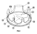
- the chamber cunnette consists of a base in the thickness of which is provided peripherally the external groove for receiving the filling material, this base being provided on one of its faces with a peripheral toothing in the form of a crenellated annular crown, each niche constituting a departure pending for the possible connection of a fluid inlet or outlet pipe introduced to the interior of said chamber through an opening of the body wall arranged in correspondence with the so that the fluid inlet or outlet lines are organized in radiant arrangement around said bedroom.
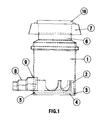
- the buried inspection chamber, object of the invention is constituted in a known manner of a tubular body 1 arranged vertically inside excavations carried out in the ground on the path of a distribution network or evacuation of fluids.
- such a room inspection performs two main functions.
- Her first function is to allow monitoring of the network by means of materials or people introduced to the interior of the chamber for maintenance, network maintenance and / or renovation.
- a second function of this room is to provide continuity hydraulic flow through the effluents.
- These effluents can be of various origins: rain, urban, industrial ... Obviously, other fluids can be brought through such a room.
- Networks incorporating such inspection chambers are designed to have to resist at least ten years. They therefore require a permanent inspection and control.
- the body 1 is buried vertically and closed at its part lower by a profiled bottom element or cunette 2.
- this body 1 is generally made up of several elements.
- this body 1 has at its upper part an access port through which it is possible to inspect said circuit.
- This body access port is delimited by means of a head element 6 or reducer assembled to the rest of the body, usually by means of a attached.
- This head element 6 is equipped with a cover 16 or closing pad placed at ground level. This cover or closing pad is generally made of cast iron.
- a lost annular formwork 7 is threaded onto the head element 6 of the body 1 and supports the closing element 16 of the head element 6.
- This load balancer therefore plays the role of floating slab. It is essential that it be detached from the head element 6 of the bedroom.
- This load-sharing element 7 will therefore rest on compacted soil.
- This annular formwork 7 is therefore, after the installation of the chamber body in a site previously cleared, filled with concrete ensuring rigidity of the whole.
- the body 1 of the chamber is closed at its lower part by a profiled bottom element 2 or wedge.
- Body 1 and bottom element 2 are made of synthetic material for the reasons explained above, namely lightness and insensitivity to aggressive effluents in particular H 2 S.
- the bottom element 2 is in particular made of polyurethane. This bottom element 2 is molded by low pressure injection of said polyurethane.
- the bottom element 2 is completely independent, at the time of its manufacture, of the body of the room it is possible to get a background element which the structure has an increasing density gradient of the central part towards the external faces of said element thus giving it a mechanical structure equivalent to an H beam, in which each face of the bottom element corresponds to a branch of H.
- the polyurethane material is injected so that this material will be much more compact in the outer part of the room while it it will be much less in the central part of the room.
- an H-structure of said part 2 itself giving good mechanical strength greater than identical compact structure, especially when the inspection chamber is subjected to the action of a sheet phreatic.
- the tubular body 1 and the profiled bottom element or cunette 2 must be assembled in such a way that perfect sealing and mechanical strength are obtained at the connection between tubular body 1 and element profiled bottom 2.
- the tubular body 1 and the bottom element 2 respectively have one a internal peripheral groove 3, the other a throat external device 4, said grooves 3,4 being arranged to come next when introducing the cunette 2 in the body 1.
- This introduction of the cunette 2 in the body 1 is usually done by force.
- the cunette 2 is dimensioned so that that it fits perfectly in the body 1 of the room inspection. Because of this perfect adaptation of the Cunette 2 in the body 1 of the chamber, we solve also the problem of the initial ovalization of the bodies of room.
- the internal peripheral groove 3 of the body 1 formed on the internal face of said body comprises at least one orifice 14 communicating with the outside of the tubular body 1 for allow the injection of a filling material 5 into grooves 3 and 4.
- This material 5 provides both tightness and mechanical strength of the connection like this has been clarified above.
- This material 5 is generally polyurethane.
- two orifices 14 and 15 communicating with the exterior of the body 1.
- one of the orifices 14 is used for the injection of this material, the other orifice 15 at degassing of the spaces to be filled during injection of the material 5.
- a template housed inside the chamber resting on the bottom element 2. This template allows to limit the creep of the filling material 5, this creep being shown in Figure 2.
- the external groove 4 for receiving the filling material 5 of the cunette 2 is formed in the thickness of a base of the cunette on the periphery of the latter.
- This the base of the cunette is also provided, on one of its sides, of peripheral teeth 10 under the form of a crenellated annular crown. This crown is intended to come to be applied more or less closely against the internal walls of the body 1 of the chamber inspection once the bottom element 2 is positioned at inside the body 1.
- Each slot 11 of this crown is arranged to come opposite an orifice 9 capable of being formed in the wall of the chamber body for connection of a line 8 for inlet or outlet of fluid to said bedroom.
- the body 1 is originally presented in the form of a simple tube comprising a peripheral groove 3 formed on its inner wall.
- This tubular body has on its outer wall marking marks of holes 9 to be drilled for connecting pipes 8 to said body. So, it is the user who decides on site the number of orifices 9 to be practiced in said body in depending on the connections to be made. This results in a great versatility of the inspection chamber suitable for adapt to multiple network configurations.
- the tubular body already has a hole made in the factory for the connection of a fluid outlet pipe 8, the other orifices being made on site. In that case, the hole is closed by means of a removable mounted plug on said body 1.
- a pipe 8 which is generally a pipe fluid inlet when the embodiment of the body 1 is of the type described above.
- each slot 11 of the cunette 2 presents on its around a shoulder 13 forming a stop during the axial introduction of an inlet pipe 8 or fluid outlet through an orifice 9 formed in correspondence of the niche 11 in the wall of the body 1 of room, the user is effortlessly assured of correct positioning of the pipe 8 inside said room.
- the profiled element 2 has at least one slot 11 corresponding to a fluid inlet and at least one slot 11A corresponding to an output of fluid of said chamber, each slot 11 of inlet of fluid being connected to at least one outlet slot of fluid 11A by a hydraulic profile 12 formed on the surface of the base of the cunette, this profile ensuring a flow directional of the fluid inside the cunette.
- the bottom element profile 2 has at most five fluid inlets and one common fluid outlet, each hydraulic profile 12 being directed from a fluid inlet towards the common exit.
- hydraulic profile is meant a shape curved, similar to a gutter profile, arranged at the surface of the base of the profiled bottom element 2, this shape being profiled to ensure flow direction of the flow of fluid entering said chamber.
Landscapes
- Engineering & Computer Science (AREA)
- Civil Engineering (AREA)
- Structural Engineering (AREA)
- General Life Sciences & Earth Sciences (AREA)
- Mining & Mineral Resources (AREA)
- Paleontology (AREA)
- Environmental & Geological Engineering (AREA)
- General Engineering & Computer Science (AREA)
- Life Sciences & Earth Sciences (AREA)
- Underground Structures, Protecting, Testing And Restoring Foundations (AREA)
- Investigating Or Analyzing Materials By The Use Of Magnetic Means (AREA)
- Analysing Materials By The Use Of Radiation (AREA)
- Geophysics And Detection Of Objects (AREA)
- Sewage (AREA)
- Burglar Alarm Systems (AREA)
Applications Claiming Priority (2)
| Application Number | Priority Date | Filing Date | Title |
|---|---|---|---|
| FR9716139 | 1997-12-19 | ||
| FR9716139A FR2772806B1 (fr) | 1997-12-19 | 1997-12-19 | Chambre d'inspection de reseaux enterree |
Publications (2)
| Publication Number | Publication Date |
|---|---|
| EP0924352A1 true EP0924352A1 (de) | 1999-06-23 |
| EP0924352B1 EP0924352B1 (de) | 2001-07-04 |
Family
ID=9514827
Family Applications (1)
| Application Number | Title | Priority Date | Filing Date |
|---|---|---|---|
| EP98403210A Expired - Lifetime EP0924352B1 (de) | 1997-12-19 | 1998-12-18 | Inspektionskammer für unterirdisches Leitungssystem |
Country Status (5)
| Country | Link |
|---|---|
| EP (1) | EP0924352B1 (de) |
| AT (1) | ATE202816T1 (de) |
| DE (1) | DE69801038T2 (de) |
| ES (1) | ES2161028T3 (de) |
| FR (1) | FR2772806B1 (de) |
Families Citing this family (1)
| Publication number | Priority date | Publication date | Assignee | Title |
|---|---|---|---|---|
| DE20209714U1 (de) | 2002-06-22 | 2002-10-17 | Hauraton Betonwarenfabrik GmbH & Co. KG, 76437 Rastatt | Schachtsystem |
Citations (4)
| Publication number | Priority date | Publication date | Assignee | Title |
|---|---|---|---|---|
| FR2093161A5 (de) * | 1970-06-02 | 1972-01-28 | Pont A Mousson | |
| FR2341015A1 (fr) * | 1976-02-12 | 1977-09-09 | Blisse Christel | Procede pour l'erection de puits, notamment pour les egouts, et puits realise par la mise en oeuvre de ce procede |
| US4253282A (en) * | 1978-02-15 | 1981-03-03 | Swartz Benjamin E | Preformed manhole base section construction |
| FR2670519A1 (fr) * | 1990-12-12 | 1992-06-19 | Pont A Mousson | Etancheite d'interface entre deux parois en materiaux cimenteux. |
-
1997
- 1997-12-19 FR FR9716139A patent/FR2772806B1/fr not_active Expired - Fee Related
-
1998
- 1998-12-18 ES ES98403210T patent/ES2161028T3/es not_active Expired - Lifetime
- 1998-12-18 DE DE69801038T patent/DE69801038T2/de not_active Expired - Fee Related
- 1998-12-18 AT AT98403210T patent/ATE202816T1/de not_active IP Right Cessation
- 1998-12-18 EP EP98403210A patent/EP0924352B1/de not_active Expired - Lifetime
Patent Citations (4)
| Publication number | Priority date | Publication date | Assignee | Title |
|---|---|---|---|---|
| FR2093161A5 (de) * | 1970-06-02 | 1972-01-28 | Pont A Mousson | |
| FR2341015A1 (fr) * | 1976-02-12 | 1977-09-09 | Blisse Christel | Procede pour l'erection de puits, notamment pour les egouts, et puits realise par la mise en oeuvre de ce procede |
| US4253282A (en) * | 1978-02-15 | 1981-03-03 | Swartz Benjamin E | Preformed manhole base section construction |
| FR2670519A1 (fr) * | 1990-12-12 | 1992-06-19 | Pont A Mousson | Etancheite d'interface entre deux parois en materiaux cimenteux. |
Also Published As
| Publication number | Publication date |
|---|---|
| ATE202816T1 (de) | 2001-07-15 |
| FR2772806B1 (fr) | 2000-02-18 |
| FR2772806A1 (fr) | 1999-06-25 |
| DE69801038T2 (de) | 2002-03-14 |
| DE69801038D1 (de) | 2001-08-09 |
| ES2161028T3 (es) | 2001-11-16 |
| EP0924352B1 (de) | 2001-07-04 |
Similar Documents
| Publication | Publication Date | Title |
|---|---|---|
| EP0081402B1 (de) | Verfahren zur Herstellung von hohlen Elementen wie etwa Leitungen, Silos oder Bunkern | |
| EP0856117B1 (de) | Modulare manschette zum schutz zur reparatur oder zur auskleidung einer rohrleitung | |
| FR2526856A1 (fr) | Systeme de cuvelage par voussoirs, notamment pour realiser des tunnels ou des galeries souterraines et instrument de verification de sa mise en place | |
| EP0244890A2 (de) | Verfahren zur Herstellung von hohlen Elementen, wie etwa Leitungen, Silos oder Bunker und Elemente, hergestellt durch dieses Verfahren | |
| EP0310488B1 (de) | Reinigungsöffnung für Anlagen zum Transportieren von Flüssigkeiten | |
| EP0924352B1 (de) | Inspektionskammer für unterirdisches Leitungssystem | |
| CA1184769A (fr) | Plate-forme marine adaptee pour faciliter la detection d'eventuelles fissures | |
| OA10392A (en) | Conduite de circulation de fluide | |
| FR3099536A1 (fr) | Raccord pour jonction de pipeline à double enveloppe | |
| EP0128082B1 (de) | Mauerdurchgangselement für Installationsrohre eines Gebäudes | |
| FR2918357A1 (fr) | Citerne, en particulier citerne enterree | |
| FR2949491A1 (fr) | Dispositif de reservation de passages de gaines et procede de formation d'une paroi en beton au moyen d'un tel dispositif de reservation | |
| FR2555284A1 (fr) | Joint etanche et dispositif de raccordement pour des canalisations, notamment sur des installations de voirie | |
| FR2871824A1 (fr) | Elements-cadres prefabriques pour la realisation de tunnels et de canaux et son application a des bassins de reserve d'eau de type enterre, semi-enterre ou non enterre | |
| CA1150649A (fr) | Dispositif d'obturation etanche d'un orifice perce dans un paroi metallique | |
| FR2539782A1 (fr) | Poutre sollicitee en flexion en beton precontraint ou en beton arme | |
| EP4259959B1 (de) | Fitting für doppelwandige rohrverbindung | |
| EP4079983B1 (de) | Hebestation für abwasser mit verstärktem boden | |
| FR2597673A1 (fr) | Etancheite des fonds d'armoire et de coffret. | |
| CA2349680A1 (fr) | Dispositif de protection d'epissures | |
| EP0887479A1 (de) | Vorgefertigter Schacht zum Anschluss und Inspektion von Abwasserkanälen, und Verfahren zur Installation eines solchen Schachts | |
| EP1627958A1 (de) | Schachtanordnung zum Einbau in Verkehrswegen | |
| FR2526461A1 (fr) | Cuvette de puits dit regard de visite | |
| FR2657371A1 (fr) | Bac ou boitier a empreintes de casse a etancheite amelioree de jonction avec des canalisations et joints d'etancheite adaptes. | |
| FR2864833A1 (fr) | Element de regard pour canalisation, et son joint d'etancheite |
Legal Events
| Date | Code | Title | Description |
|---|---|---|---|
| PUAI | Public reference made under article 153(3) epc to a published international application that has entered the european phase |
Free format text: ORIGINAL CODE: 0009012 |
|
| AK | Designated contracting states |
Kind code of ref document: A1 Designated state(s): AT BE CH CY DE DK ES FI FR GB GR IE IT LI LU MC NL PT SE |
|
| AX | Request for extension of the european patent |
Free format text: AL;LT;LV;MK;RO;SI |
|
| 17P | Request for examination filed |
Effective date: 19991207 |
|
| AKX | Designation fees paid |
Free format text: AT BE CH CY DE DK ES FI FR GB GR IE IT LI LU MC NL PT SE |
|
| AXX | Extension fees paid |
Free format text: AL PAYMENT 19991207;LT PAYMENT 19991207;LV PAYMENT 19991207;RO PAYMENT 19991207;SI PAYMENT 19991207 |
|
| GRAG | Despatch of communication of intention to grant |
Free format text: ORIGINAL CODE: EPIDOS AGRA |
|
| 17Q | First examination report despatched |
Effective date: 20000904 |
|
| GRAG | Despatch of communication of intention to grant |
Free format text: ORIGINAL CODE: EPIDOS AGRA |
|
| GRAH | Despatch of communication of intention to grant a patent |
Free format text: ORIGINAL CODE: EPIDOS IGRA |
|
| GRAH | Despatch of communication of intention to grant a patent |
Free format text: ORIGINAL CODE: EPIDOS IGRA |
|
| GRAA | (expected) grant |
Free format text: ORIGINAL CODE: 0009210 |
|
| AK | Designated contracting states |
Kind code of ref document: B1 Designated state(s): AT BE CH CY DE DK ES FI FR GB GR IE IT LI LU MC NL PT SE |
|
| AX | Request for extension of the european patent |
Free format text: AL PAYMENT 19991207;LT PAYMENT 19991207;LV PAYMENT 19991207;RO PAYMENT 19991207;SI PAYMENT 19991207 |
|
| LTIE | Lt: invalidation of european patent or patent extension | ||
| PG25 | Lapsed in a contracting state [announced via postgrant information from national office to epo] |
Ref country code: NL Free format text: LAPSE BECAUSE OF FAILURE TO SUBMIT A TRANSLATION OF THE DESCRIPTION OR TO PAY THE FEE WITHIN THE PRESCRIBED TIME-LIMIT Effective date: 20010704 Ref country code: IE Free format text: LAPSE BECAUSE OF FAILURE TO SUBMIT A TRANSLATION OF THE DESCRIPTION OR TO PAY THE FEE WITHIN THE PRESCRIBED TIME-LIMIT Effective date: 20010704 Ref country code: FI Free format text: LAPSE BECAUSE OF FAILURE TO SUBMIT A TRANSLATION OF THE DESCRIPTION OR TO PAY THE FEE WITHIN THE PRESCRIBED TIME-LIMIT Effective date: 20010704 Ref country code: CY Free format text: LAPSE BECAUSE OF NON-PAYMENT OF DUE FEES Effective date: 20010704 Ref country code: AT Free format text: LAPSE BECAUSE OF FAILURE TO SUBMIT A TRANSLATION OF THE DESCRIPTION OR TO PAY THE FEE WITHIN THE PRESCRIBED TIME-LIMIT Effective date: 20010704 |
|
| REF | Corresponds to: |
Ref document number: 202816 Country of ref document: AT Date of ref document: 20010715 Kind code of ref document: T |
|
| REG | Reference to a national code |
Ref country code: CH Ref legal event code: EP |
|
| REG | Reference to a national code |
Ref country code: IE Ref legal event code: FG4D Free format text: FRENCH |
|
| REF | Corresponds to: |
Ref document number: 69801038 Country of ref document: DE Date of ref document: 20010809 |
|
| ITF | It: translation for a ep patent filed | ||
| PG25 | Lapsed in a contracting state [announced via postgrant information from national office to epo] |
Ref country code: SE Free format text: LAPSE BECAUSE OF FAILURE TO SUBMIT A TRANSLATION OF THE DESCRIPTION OR TO PAY THE FEE WITHIN THE PRESCRIBED TIME-LIMIT Effective date: 20011004 Ref country code: PT Free format text: LAPSE BECAUSE OF FAILURE TO SUBMIT A TRANSLATION OF THE DESCRIPTION OR TO PAY THE FEE WITHIN THE PRESCRIBED TIME-LIMIT Effective date: 20011004 Ref country code: DK Free format text: LAPSE BECAUSE OF FAILURE TO SUBMIT A TRANSLATION OF THE DESCRIPTION OR TO PAY THE FEE WITHIN THE PRESCRIBED TIME-LIMIT Effective date: 20011004 |
|
| PG25 | Lapsed in a contracting state [announced via postgrant information from national office to epo] |
Ref country code: GR Free format text: LAPSE BECAUSE OF FAILURE TO SUBMIT A TRANSLATION OF THE DESCRIPTION OR TO PAY THE FEE WITHIN THE PRESCRIBED TIME-LIMIT Effective date: 20011005 |
|
| GBT | Gb: translation of ep patent filed (gb section 77(6)(a)/1977) |
Effective date: 20011004 |
|
| REG | Reference to a national code |
Ref country code: ES Ref legal event code: FG2A Ref document number: 2161028 Country of ref document: ES Kind code of ref document: T3 |
|
| NLV1 | Nl: lapsed or annulled due to failure to fulfill the requirements of art. 29p and 29m of the patents act | ||
| PG25 | Lapsed in a contracting state [announced via postgrant information from national office to epo] |
Ref country code: MC Free format text: LAPSE BECAUSE OF NON-PAYMENT OF DUE FEES Effective date: 20011218 Ref country code: LU Free format text: LAPSE BECAUSE OF NON-PAYMENT OF DUE FEES Effective date: 20011218 |
|
| PG25 | Lapsed in a contracting state [announced via postgrant information from national office to epo] |
Ref country code: BE Free format text: LAPSE BECAUSE OF NON-PAYMENT OF DUE FEES Effective date: 20011231 |
|
| REG | Reference to a national code |
Ref country code: GB Ref legal event code: IF02 |
|
| PLBE | No opposition filed within time limit |
Free format text: ORIGINAL CODE: 0009261 |
|
| STAA | Information on the status of an ep patent application or granted ep patent |
Free format text: STATUS: NO OPPOSITION FILED WITHIN TIME LIMIT |
|
| BERE | Be: lapsed |
Owner name: PAPIN HOLDING Effective date: 20011231 |
|
| 26N | No opposition filed | ||
| PG25 | Lapsed in a contracting state [announced via postgrant information from national office to epo] |
Ref country code: LI Free format text: LAPSE BECAUSE OF NON-PAYMENT OF DUE FEES Effective date: 20021231 Ref country code: CH Free format text: LAPSE BECAUSE OF NON-PAYMENT OF DUE FEES Effective date: 20021231 |
|
| REG | Reference to a national code |
Ref country code: CH Ref legal event code: PL |
|
| PGFP | Annual fee paid to national office [announced via postgrant information from national office to epo] |
Ref country code: ES Payment date: 20061229 Year of fee payment: 9 |
|
| PGFP | Annual fee paid to national office [announced via postgrant information from national office to epo] |
Ref country code: IT Payment date: 20061231 Year of fee payment: 9 |
|
| PGFP | Annual fee paid to national office [announced via postgrant information from national office to epo] |
Ref country code: DE Payment date: 20070103 Year of fee payment: 9 |
|
| PGFP | Annual fee paid to national office [announced via postgrant information from national office to epo] |
Ref country code: GB Payment date: 20070105 Year of fee payment: 9 |
|
| GBPC | Gb: european patent ceased through non-payment of renewal fee |
Effective date: 20071218 |
|
| PG25 | Lapsed in a contracting state [announced via postgrant information from national office to epo] |
Ref country code: DE Free format text: LAPSE BECAUSE OF NON-PAYMENT OF DUE FEES Effective date: 20080701 |
|
| PG25 | Lapsed in a contracting state [announced via postgrant information from national office to epo] |
Ref country code: GB Free format text: LAPSE BECAUSE OF NON-PAYMENT OF DUE FEES Effective date: 20071218 |
|
| REG | Reference to a national code |
Ref country code: ES Ref legal event code: FD2A Effective date: 20071219 |
|
| PG25 | Lapsed in a contracting state [announced via postgrant information from national office to epo] |
Ref country code: ES Free format text: LAPSE BECAUSE OF NON-PAYMENT OF DUE FEES Effective date: 20071219 |
|
| PG25 | Lapsed in a contracting state [announced via postgrant information from national office to epo] |
Ref country code: IT Free format text: LAPSE BECAUSE OF NON-PAYMENT OF DUE FEES Effective date: 20071218 |
|
| PGFP | Annual fee paid to national office [announced via postgrant information from national office to epo] |
Ref country code: FR Payment date: 20091216 Year of fee payment: 12 |
|
| REG | Reference to a national code |
Ref country code: FR Ref legal event code: ST Effective date: 20110831 |
|
| PG25 | Lapsed in a contracting state [announced via postgrant information from national office to epo] |
Ref country code: FR Free format text: LAPSE BECAUSE OF NON-PAYMENT OF DUE FEES Effective date: 20110103 |