EP0924353B1 - Vorrichtung zur pneumatischen Betätigung eines Spülkastens - Google Patents
Vorrichtung zur pneumatischen Betätigung eines Spülkastens Download PDFInfo
- Publication number
- EP0924353B1 EP0924353B1 EP98811139A EP98811139A EP0924353B1 EP 0924353 B1 EP0924353 B1 EP 0924353B1 EP 98811139 A EP98811139 A EP 98811139A EP 98811139 A EP98811139 A EP 98811139A EP 0924353 B1 EP0924353 B1 EP 0924353B1
- Authority
- EP
- European Patent Office
- Prior art keywords
- bellows
- buttons
- housing
- pressure pulse
- button
- Prior art date
- Legal status (The legal status is an assumption and is not a legal conclusion. Google has not performed a legal analysis and makes no representation as to the accuracy of the status listed.)
- Expired - Lifetime
Links
Images

Classifications
-
- E—FIXED CONSTRUCTIONS
- E03—WATER SUPPLY; SEWERAGE
- E03D—WATER-CLOSETS OR URINALS WITH FLUSHING DEVICES; FLUSHING VALVES THEREFOR
- E03D5/00—Special constructions of flushing devices, e.g. closed flushing system
- E03D5/02—Special constructions of flushing devices, e.g. closed flushing system operated mechanically or hydraulically (or pneumatically) also details such as push buttons, levers and pull-card therefor
- E03D5/024—Operated hydraulically or pneumatically
-
- E—FIXED CONSTRUCTIONS
- E03—WATER SUPPLY; SEWERAGE
- E03D—WATER-CLOSETS OR URINALS WITH FLUSHING DEVICES; FLUSHING VALVES THEREFOR
- E03D1/00—Water flushing devices with cisterns ; Setting up a range of flushing devices or water-closets; Combinations of several flushing devices
- E03D1/02—High-level flushing systems
- E03D1/14—Cisterns discharging variable quantities of water also cisterns with bell siphons in combination with flushing valves
Definitions
- the invention relates to a device for pneumatic actuation according to the preamble of claim 1.
- a device of the type mentioned is in the prior art WO 94/23141 become known.
- CH-A-424 664 Another actuating device is known from CH-A-424 664 become.
- This device is designed as a hand lever and has a push button that is slidable in the housing is stored. The inner end of the push button lies on one Membrane that is deformable to exert a pressure pulse is.
- a similar device has become known from DE-C-23 50 189. This is used to exercise a pressure pulse domed rubber membrane pressed in by hand or a tubular membrane pressed together with a push button.
- the invention has for its object a device to create the type mentioned, which enables remote triggering.
- the device according to the invention enables the actuation of a Cistern with two different flush volumes.
- a Cistern with two different flush volumes When pressing one button on the cistern, for example Full rinse and with the other button, for example, a partial rinse to be triggered.
- Cisterns with two different ones Flush volumes have long been known per se. So far this has been but only with buttons located directly on the cistern triggered.
- the device according to the invention now enables one Remote activation of such cisterns, which are ecological and economic reasons are very advantageous.
- the pressure pulse generator has two bellows, one bellows with one button and the other bellows with the other button works together.
- these two bellows according to a further development of the invention laterally flattened bellows, For example, these can be used for small sizes be housed in a can. Enable this construction mass retrofitting of an already installed push button. A special one reliable functioning is guaranteed if the bellows have support folds drawn in laterally. This Support folds prevent uncontrolled deformation of the Bellows and ensure precisely defined pressure impulses.
- It serves also the training, according to which the buttons on the underside in each case have a guide part, which is placed on a bellows and leads it to the side. For pressing the button the bellows is then guided through this guide part.
- the two bellows are according to a further development of the invention releasably attached to a holding and guiding part, which in the bottom part of the housing is inserted.
- a holding and guiding part Preferably owns this holding and guiding part at least two, preferably three mounting positions. This enables that two or one bellows can be fastened in the housing.
- the device 1 is a hand lever, also called a button essentially from a housing 2, a cover 3, two buttons 4 and 5, two bellows 6 and one in the lower part of the housing stored holding and guiding part 8.
- These parts are releasable by locking means and plugging together connected.
- the individual parts are therefore without the use of Exchangeable tools and non-destructive. Even the assembly takes place without the use of tools by locking means are explained in more detail below.
- the housing 2 is can-shaped and has in its Bottom four attachment points 26 with which the housing with Screws not shown here in a niche of a building wall is attachable.
- Two openings 24 are also incorporated in the base, through the respective flexible pressure line 27 ( Figure 2) are pulled through. Inside the housing 2 are these pressure lines 27 are each connected to a nipple 9.
- a holding and guiding part 8 is inserted into the housing 2, on which the two nipples 9, the two bellows 6, the two buttons 4 and 5 and the frame cover 3 are releasably attached.
- the two nipples 9 are from the bottom of part 8, respectively airtight in a tubular, rubber-elastic approach 28 one Bellows 6 used. As Figure 2 shows, this towers over upper end of the nipple 9, the opening 28 and engages in a corresponding, opening of the approach not specified here 28 a.
- the nipples 9 each connect a pneumatic one Line 27 with a bellows 6.
- the holding and guiding part 8 has a slot 14 which has a large one circular opening 14d and three smaller extensions 14a, 14b and 14c.
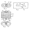
- the bellows 6 have for their attachment in this slot 14 a plate-shaped on the underside Approach 12 on, as Figure 4 clearly shows.
- a first Attach bellows to part 8 the plate 12 through the large opening 14d inserted and the bellows 6 in the slot 14 in Figure 6 shifted to the left until the plate 12 the slot 14 snaps into extension 14a.
- a second bellows 6 is also inserted with his plate 12 through the opening 14d and shifted to the right in FIG. 6 until extension 14c. is only one bellows 6 is provided, this is shown in FIGS moved to extension 14b.
- the extension 14b thus allows the releasable attachment of a single bellows 6 approximately in the Middle of housing 2.
- each bellows 6 has two molded parts on its base Cam 30, each in an opening 25 of part 8 intervention.
- the plate 12 has a passage in the middle, such as Figure 2 shows. In this passage 28 is a neck-shaped Approach of a nipple 9 can be used.
- the plate 12 is out rubber-elastic material like the rest of the bellows 6 and seals the nipple 9 against the bellows 6.
- the two nipples 9 are each detachably and tightly connected to a bellows 6.
- the part 8 has several elastically deflectable upward Locking tongues 16 and 22 for fastening the frame-shaped Cover 3 and buttons 4 and 5.
- Figure 1 shows one of the Locking tongues 16, which have a locking lug in an opening 15 of the frame cover 3 engages.
- the two buttons 4 and 5 are each hood-shaped and according to FIG. 2, shown here using the example of the key 5, a curved upper wall 4b and laterally downwards in an opening 3a of the frame cover 3 engaging guide wall 5a.
- the key 5 has a smaller key area than that Key 4, but basically both keys are similar.
- the larger button 4 is for triggering a full flush and the smaller button 5 is provided for triggering a partial rinse.
- the keys 4 and 5 are by the locking tabs 22nd with the holding and guiding part 8 slidably mounted and in locked in the upper position. Keys 4 and 5 can be used in the in the position shown in Figures 1 and 2 each individually be moved down. The top position shown is by a upper stop determined.
- FIG. 2 shows, the keys 4 overlap and 5 a bellows 6 each.
- the one arranged below the button 4 Bellows is omitted for drawing reasons, but is otherwise identical to the drawn bellows 6 on a key 4 or 5, the respective bellows 6 by a Plate-shaped guide part attached to the bottom of the button 7 led.
- This guide part 7 has a central one Connecting part 31 with a lower nozzle 21 and an upper Stub 20.
- the stub 20 is snapped into an extension 32
- the lower nozzle 21 engages in a tubular extension 33 of the bellows 6 and thus fastens the bellows 6 to part 7.
- the bellows 6 lies on the underside at its upper end on part 7 and is guided laterally on this.
- the Part 7 thus prevents that when the button 4 is depressed can deflect the upper end of the bellows 6 laterally.
- the two bellows 6 are comparatively flat with a substantially rectangular and laterally rounded cross-section.
- the bellows 6 each have a plurality of laterally drawn inwards Support folds 10 on.
- These folds 10a are usual per se Folds 10, however, so formed that they arcuate into the Intervene inside the bellows 6.
- the support folds 10a enable that the bellows 6 essentially compresses its shape maintains.
- the flat design of the two bellows 6 shown has the main advantage that this is in a rectangular housing 2 take up little space and the interior of the housing 2 is used optimally.
- the housing 2 can therefore have external dimensions be produced, which correspond to the usual keys.
- the two bellows 6, or only a bellows 6 is attached to the holding and guiding part 8. Now the means are used and the lines 27 are connected. The guide parts are now on the top of the bellows 6 7 put on. After snapping buttons 4 and 5 can the interconnected parts in the housing 2 of be used above. Finally, cover 3 snapped onto the holding frame.
Landscapes
- Engineering & Computer Science (AREA)
- Public Health (AREA)
- Health & Medical Sciences (AREA)
- Life Sciences & Earth Sciences (AREA)
- Hydrology & Water Resources (AREA)
- Water Supply & Treatment (AREA)
- Aviation & Aerospace Engineering (AREA)
- Mechanical Engineering (AREA)
- Diaphragms And Bellows (AREA)
- Electrical Discharge Machining, Electrochemical Machining, And Combined Machining (AREA)
- Waste-Gas Treatment And Other Accessory Devices For Furnaces (AREA)
- Diaphragms For Electromechanical Transducers (AREA)
- Supply Devices, Intensifiers, Converters, And Telemotors (AREA)
- Reciprocating Pumps (AREA)
- Fluid-Pressure Circuits (AREA)
Description
- Figur 1
- einen Schnitt durch eine erfindungsgemässe Vorrichtung,
- Figur 2
- einen Schnitt durch die Vorrichtung entlang der Linie II-II gemäss Figur 1,
- Figur 3
- eine Ansicht der Unterseite eines Balges,
- Figur 4
- eine Seitenansicht des Balges,
- Figur 5
- eine Ansicht der Oberseite des Balges, und
- Figur 6
- eine Ansicht des Befestigungsmittels für die wahlweise Befestigung eines oder zweier Bälge.
Claims (9)
- Vorrichtung zur pneumatischen Betätigung eines Spülkastens, mit einer in einem Gehäuse (2) gelagerten Einrichtung (4, 5) die zur Zeugung eines Druckimpulses mit einem Druckimpulsgeber (6) zusammenarbeitet, wobei die Einrichtung zwei Tasten (4, 5) und der Druckimpulsgeber (6) zwei Bälge (6) aufweist und der Druckimpulsgeber (6) so ausgebildet ist, dass durch Drücken der einen oder der anderen Taste (4, 5) wahlweise ein erster oder ein zweiter Druckimpuls erzeugbar ist, dadurch gekennzeichnet, dass der eine Balg nur mit der einen Taste (4) und der andere Balg nur mit der anderen Taste (5) zusammenarbeitet, und dass die beiden Bälge (6) als auch die Tasten (4, 5) im genannten Gehäuse (2) gelagert sind.
- Vorrichtung nach Anspruch 1, dadurch gekennzeichnet, dass die beiden Bälge (6) seitlich abgeflachte Faltenbälge sind.
- Vorrichtung nach Anspruch 3, dadurch gekennzeichnet, dass die beiden Faltenbälge (6) im Querschnitt zueinander gesehen etwa rechteckig ausgebildet sind, wobei Schmalseiten wesentlich, vorzugsweise wenigstens zweimal kürzer sind als Breitseiten.
- Vorrichtung nach einem der Ansprüche 1 bis 3, dadurch gekennzeichnet, dass die Faltenbälge (6) seitlich eingezogene Stützfalten (10a) aufweisen.
- Vorrichtung nach einem der Ansprüche 1 bis 4, dadurch gekennzeichnet, dass die Tasten (4, 5) jeweils kuppelförmig oder haubenförmig ausgebildet und mit seitlich in das Gehäuse (2) eingreifenden Wandungen (5a) verschieblich geführt sind.
- Vorrichtung nach einem der Ansprüche 1 bis 5, dadurch gekennzeichnet, dass die Tasten (4, 5) unterseitig jeweils ein Führungsteil (7) aufweisen, das auf einem Balg (6) aufgesetzt ist und diesen seitlich führt.
- Vorrichtung nach einem der Ansprüche 1 bis 6, dadurch gekennzeichnet, dass die Tasten (4, 5) Führungsmittel (5a) aufweisen, mit denen sie im Gehäuse (2) verschieblich geführt sind und dass diese Führungsmittel (5a) Rastmittel (18) zur lösbaren Befestigung der Tasten (4, 5) an einem Halte- und Führungsteil (8) aufweisen.
- Vorrichtung nach einem der Ansprüche 1 bis 7, dadurch gekennzeichnet, dass in das Gehäuse (2) ein Halte- und Führungsteil (8) lösbar eingesetzt ist, an welchem wenigstens der Druckimpulsgeber (6) lösbar befestigt ist.
- Vorrichtung nach Anspruch 8, dadurch gekennzeichnet, dass der Halte- und Führungsteil (8) Befestigungsmittel (14) mit wenigstens zwei, vorzugsweise drei Befestigungspositionen (14a, 14b, 14c) aufweist, derart, dass wahlweise zwei oder ein Balg (6) befestigbar ist.
Applications Claiming Priority (2)
| Application Number | Priority Date | Filing Date | Title |
|---|---|---|---|
| CH287697 | 1997-12-15 | ||
| CH287697 | 1997-12-15 |
Publications (3)
| Publication Number | Publication Date |
|---|---|
| EP0924353A2 EP0924353A2 (de) | 1999-06-23 |
| EP0924353A3 EP0924353A3 (de) | 2000-01-26 |
| EP0924353B1 true EP0924353B1 (de) | 2003-06-04 |
Family
ID=4243565
Family Applications (1)
| Application Number | Title | Priority Date | Filing Date |
|---|---|---|---|
| EP98811139A Expired - Lifetime EP0924353B1 (de) | 1997-12-15 | 1998-11-16 | Vorrichtung zur pneumatischen Betätigung eines Spülkastens |
Country Status (4)
| Country | Link |
|---|---|
| EP (1) | EP0924353B1 (de) |
| AT (1) | ATE242371T1 (de) |
| AU (1) | AU742152B2 (de) |
| DE (2) | DE59808615D1 (de) |
Cited By (1)
| Publication number | Priority date | Publication date | Assignee | Title |
|---|---|---|---|---|
| WO2025186053A1 (de) * | 2024-03-05 | 2025-09-12 | Grohe Ag | Vorrichtung zur betätigung einer spülung eines wcs |
Families Citing this family (7)
| Publication number | Priority date | Publication date | Assignee | Title |
|---|---|---|---|---|
| ITMI20010276U1 (it) * | 2001-05-16 | 2002-11-18 | Valsir Spa | Sistema modulare per l'allestimento di cassette di risciacquamento diapparecchi sanitari con diverse modalita' di funzionamento, e cassetta |
| ITMI20031323A1 (it) * | 2003-06-27 | 2004-12-28 | Valsir Spa | Dispositivo di comando della valvola di scarico di una cassetta di risciacquo. |
| CN101802315B (zh) * | 2007-09-20 | 2011-08-31 | 卡罗马工业有限公司 | 用于蓄水箱放出阀的气动按钮组件 |
| ATE555255T1 (de) | 2008-09-29 | 2012-05-15 | Geberit Int Ag | Pneumatische betätigungsvorrichtung |
| WO2012123050A1 (de) | 2011-03-11 | 2012-09-20 | Grohe Ag | Sanitäranlage mit spülfunktion wie beispielsweise eine toilette oder ein urinal |
| DE102022108200A1 (de) | 2022-04-05 | 2023-10-05 | Grohe Ag | Sanitäranlage mit Spülfunktion |
| DE102022108201A1 (de) | 2022-04-05 | 2023-10-05 | Grohe Ag | Sanitäranlage mit Spülfunktion |
Family Cites Families (7)
| Publication number | Priority date | Publication date | Assignee | Title |
|---|---|---|---|---|
| CH424664A (de) | 1965-08-27 | 1966-11-15 | Gebert & Cie | Handdrücker zur Betätigung eines Spülkastens |
| CH558080A (de) | 1972-10-14 | 1975-01-15 | Huba Control Ag | Betaetigungstaster fuer einen mittels fluidumsdruck betaetigbaren schalter. |
| CH641225A5 (de) * | 1979-06-05 | 1984-02-15 | Geberit Ag | Pneumatische betaetigungsvorrichtung an einem spuelkasten-ablaufventil. |
| US4809367A (en) * | 1986-08-08 | 1989-03-07 | Partall Systems (Proprietary) Limited | Cistern flushing apparatus |
| GB2276640B (en) * | 1993-03-30 | 1996-07-31 | Alan David Somerfield | Improvements in or relating to cisterns |
| IT1280896B1 (it) * | 1995-08-04 | 1998-02-11 | Plastic Investment Holding S A | Dispositivo pneumatico per l'azionamento di una valvola di scarico di una cassetta di risciacquo per wc |
| DE29808200U1 (de) * | 1997-07-07 | 1998-07-23 | Geberit Technik Ag, Jona | Betätigungsvorrichtung für ein Ablaufventil eines WC-Spülkastens |
-
1998
- 1998-11-16 EP EP98811139A patent/EP0924353B1/de not_active Expired - Lifetime
- 1998-11-16 DE DE59808615T patent/DE59808615D1/de not_active Expired - Lifetime
- 1998-11-16 AT AT98811139T patent/ATE242371T1/de active
- 1998-11-21 DE DE29820855U patent/DE29820855U1/de not_active Expired - Lifetime
- 1998-12-14 AU AU97110/98A patent/AU742152B2/en not_active Ceased
Cited By (1)
| Publication number | Priority date | Publication date | Assignee | Title |
|---|---|---|---|---|
| WO2025186053A1 (de) * | 2024-03-05 | 2025-09-12 | Grohe Ag | Vorrichtung zur betätigung einer spülung eines wcs |
Also Published As
| Publication number | Publication date |
|---|---|
| ATE242371T1 (de) | 2003-06-15 |
| EP0924353A2 (de) | 1999-06-23 |
| AU9711098A (en) | 1999-07-01 |
| AU742152B2 (en) | 2001-12-20 |
| EP0924353A3 (de) | 2000-01-26 |
| DE59808615D1 (de) | 2003-07-10 |
| DE29820855U1 (de) | 1999-03-25 |
Similar Documents
| Publication | Publication Date | Title |
|---|---|---|
| EP1236910B1 (de) | Federbelasteter, rastender Druckstift | |
| EP0924353B1 (de) | Vorrichtung zur pneumatischen Betätigung eines Spülkastens | |
| DE102011009123B4 (de) | Schalter-Anordnung mit manueller Rücksetzung | |
| DE4004197C2 (de) | Schnellverbindungsvorrichtung für Möbelscharniere | |
| DE4201570C2 (de) | Stellvorrichtung | |
| DE2719194A1 (de) | Befestigungsvorrichtung fuer einen schalter | |
| DE29617895U1 (de) | Versorgungsbalken für die Intensivpflege | |
| DE69635356T2 (de) | Elektrische Steckdose | |
| CH652269A5 (en) | Quick mounting base made of plastic, for fixing an electrical device or printed-circuit board | |
| EP0017820B1 (de) | Vorrichtung zur Verlängerung von Stösselantrieben | |
| EP0568859B1 (de) | Tableau mit werkzeuglos betätigbaren Befestigungselementen | |
| DE10250966A1 (de) | Kickdown-Element für einen Fahrpedalgeber | |
| AT407276B (de) | Scharniertopf mit lösbarer befestigung | |
| EP0877125B1 (de) | Rahmen für die Montage von Sanitärartikeln | |
| DE3802971C2 (de) | Elektrisches Installationsgerät, wie Schalter, Taster, Tastschalter od. dgl. | |
| DE2025229C3 (de) | Schwallwasserdichter Drucktastenschalter | |
| DE19527093C2 (de) | Tastenanordnung | |
| DE202017106831U1 (de) | Rundfußschalter | |
| EP0131538A2 (de) | Befestigungsvorrichtung für einen Geräteeinsatz in einer Grundplatte, insbesondere in Küchenarbeitsplatten | |
| DE4140481C1 (en) | Roof ridge covering strip made in two parts - has one part fixed to ridge board and other to tile connected by pressure activated clips. | |
| EP2716825B1 (de) | Spülkasten mit hydraulischer Betätigung | |
| DE2842774C2 (de) | Schaltungsanordnung für elektriche Blutdruckmeßgeräte | |
| DE4216855C1 (de) | Kasten, insbesondere farbkasten | |
| DE266416C (de) | ||
| DE2327170C3 (de) | Befestigungsvorrichtung für einen Drucktastenschalter |
Legal Events
| Date | Code | Title | Description |
|---|---|---|---|
| PUAI | Public reference made under article 153(3) epc to a published international application that has entered the european phase |
Free format text: ORIGINAL CODE: 0009012 |
|
| AK | Designated contracting states |
Kind code of ref document: A2 Designated state(s): AT BE CH DE DK ES FI FR GB IT LI MC NL SE |
|
| AX | Request for extension of the european patent |
Free format text: AL;LT;LV;MK;RO;SI |
|
| PUAL | Search report despatched |
Free format text: ORIGINAL CODE: 0009013 |
|
| AK | Designated contracting states |
Kind code of ref document: A3 Designated state(s): AT BE CH CY DE DK ES FI FR GB GR IE IT LI LU MC NL PT SE |
|
| AX | Request for extension of the european patent |
Free format text: AL;LT;LV;MK;RO;SI |
|
| 17P | Request for examination filed |
Effective date: 20000212 |
|
| AKX | Designation fees paid |
Free format text: AT BE CH DE DK ES FI FR GB IT LI MC NL SE |
|
| AXX | Extension fees paid |
Free format text: SI PAYMENT 20000212 |
|
| 17Q | First examination report despatched |
Effective date: 20020917 |
|
| GRAH | Despatch of communication of intention to grant a patent |
Free format text: ORIGINAL CODE: EPIDOS IGRA |
|
| GRAH | Despatch of communication of intention to grant a patent |
Free format text: ORIGINAL CODE: EPIDOS IGRA |
|
| GRAA | (expected) grant |
Free format text: ORIGINAL CODE: 0009210 |
|
| AK | Designated contracting states |
Designated state(s): AT BE CH DE DK ES FI FR GB IT LI MC NL SE |
|
| AX | Request for extension of the european patent |
Extension state: SI |
|
| PG25 | Lapsed in a contracting state [announced via postgrant information from national office to epo] |
Ref country code: FI Free format text: LAPSE BECAUSE OF FAILURE TO SUBMIT A TRANSLATION OF THE DESCRIPTION OR TO PAY THE FEE WITHIN THE PRESCRIBED TIME-LIMIT Effective date: 20030604 |
|
| REG | Reference to a national code |
Ref country code: GB Ref legal event code: FG4D Free format text: NOT ENGLISH |
|
| REG | Reference to a national code |
Ref country code: CH Ref legal event code: NV Representative=s name: INFINEON TECHNOLOGIES SCHWEIZ AG Ref country code: CH Ref legal event code: EP |
|
| REF | Corresponds to: |
Ref document number: 59808615 Country of ref document: DE Date of ref document: 20030710 Kind code of ref document: P |
|
| GBT | Gb: translation of ep patent filed (gb section 77(6)(a)/1977) | ||
| PG25 | Lapsed in a contracting state [announced via postgrant information from national office to epo] |
Ref country code: SE Free format text: LAPSE BECAUSE OF FAILURE TO SUBMIT A TRANSLATION OF THE DESCRIPTION OR TO PAY THE FEE WITHIN THE PRESCRIBED TIME-LIMIT Effective date: 20030904 Ref country code: DK Free format text: LAPSE BECAUSE OF FAILURE TO SUBMIT A TRANSLATION OF THE DESCRIPTION OR TO PAY THE FEE WITHIN THE PRESCRIBED TIME-LIMIT Effective date: 20030904 |
|
| PG25 | Lapsed in a contracting state [announced via postgrant information from national office to epo] |
Ref country code: ES Free format text: LAPSE BECAUSE OF FAILURE TO SUBMIT A TRANSLATION OF THE DESCRIPTION OR TO PAY THE FEE WITHIN THE PRESCRIBED TIME-LIMIT Effective date: 20030915 |
|
| PG25 | Lapsed in a contracting state [announced via postgrant information from national office to epo] |
Ref country code: MC Free format text: LAPSE BECAUSE OF NON-PAYMENT OF DUE FEES Effective date: 20031130 |
|
| ET | Fr: translation filed | ||
| PLBE | No opposition filed within time limit |
Free format text: ORIGINAL CODE: 0009261 |
|
| STAA | Information on the status of an ep patent application or granted ep patent |
Free format text: STATUS: NO OPPOSITION FILED WITHIN TIME LIMIT |
|
| 26N | No opposition filed |
Effective date: 20040305 |
|
| REG | Reference to a national code |
Ref country code: CH Ref legal event code: PCAR Free format text: ISLER & PEDRAZZINI AG;POSTFACH 1772;8027 ZUERICH (CH) |
|
| REG | Reference to a national code |
Ref country code: GB Ref legal event code: 732E Free format text: REGISTERED BETWEEN 20100121 AND 20100127 |
|
| REG | Reference to a national code |
Ref country code: CH Ref legal event code: PUE Owner name: GEBERIT INTERNATIONAL AG Free format text: GEBERIT TECHNIK AG#SCHACHENSTRASSE 77#8645 JONA (CH) -TRANSFER TO- GEBERIT INTERNATIONAL AG#SCHACHENSTRASSE 77#8645 JONA (CH) |
|
| REG | Reference to a national code |
Ref country code: NL Ref legal event code: SD Effective date: 20100304 |
|
| REG | Reference to a national code |
Ref country code: FR Ref legal event code: TP |
|
| PGFP | Annual fee paid to national office [announced via postgrant information from national office to epo] |
Ref country code: AT Payment date: 20101112 Year of fee payment: 13 |
|
| PGFP | Annual fee paid to national office [announced via postgrant information from national office to epo] |
Ref country code: CH Payment date: 20111130 Year of fee payment: 14 Ref country code: NL Payment date: 20111124 Year of fee payment: 14 |
|
| PGFP | Annual fee paid to national office [announced via postgrant information from national office to epo] |
Ref country code: BE Payment date: 20111110 Year of fee payment: 14 |
|
| BERE | Be: lapsed |
Owner name: GEBERIT INTERNATIONAL A.G. Effective date: 20121130 |
|
| REG | Reference to a national code |
Ref country code: NL Ref legal event code: V1 Effective date: 20130601 |
|
| REG | Reference to a national code |
Ref country code: CH Ref legal event code: PL |
|
| REG | Reference to a national code |
Ref country code: AT Ref legal event code: MM01 Ref document number: 242371 Country of ref document: AT Kind code of ref document: T Effective date: 20121116 |
|
| PG25 | Lapsed in a contracting state [announced via postgrant information from national office to epo] |
Ref country code: AT Free format text: LAPSE BECAUSE OF NON-PAYMENT OF DUE FEES Effective date: 20121116 Ref country code: CH Free format text: LAPSE BECAUSE OF NON-PAYMENT OF DUE FEES Effective date: 20121130 Ref country code: LI Free format text: LAPSE BECAUSE OF NON-PAYMENT OF DUE FEES Effective date: 20121130 |
|
| PG25 | Lapsed in a contracting state [announced via postgrant information from national office to epo] |
Ref country code: BE Free format text: LAPSE BECAUSE OF NON-PAYMENT OF DUE FEES Effective date: 20121130 Ref country code: NL Free format text: LAPSE BECAUSE OF NON-PAYMENT OF DUE FEES Effective date: 20130601 |
|
| REG | Reference to a national code |
Ref country code: DE Ref legal event code: R082 Ref document number: 59808615 Country of ref document: DE Representative=s name: HOEGER, STELLRECHT & PARTNER PATENTANWAELTE MB, DE Ref country code: DE Ref legal event code: R082 Ref document number: 59808615 Country of ref document: DE Representative=s name: HOEGER, STELLRECHT & PARTNER PATENTANWAELTE, DE |
|
| PGFP | Annual fee paid to national office [announced via postgrant information from national office to epo] |
Ref country code: FR Payment date: 20141119 Year of fee payment: 17 Ref country code: GB Payment date: 20141119 Year of fee payment: 17 Ref country code: DE Payment date: 20141119 Year of fee payment: 17 |
|
| PGFP | Annual fee paid to national office [announced via postgrant information from national office to epo] |
Ref country code: IT Payment date: 20141126 Year of fee payment: 17 |
|
| REG | Reference to a national code |
Ref country code: DE Ref legal event code: R082 Ref document number: 59808615 Country of ref document: DE Representative=s name: HOEGER, STELLRECHT & PARTNER PATENTANWAELTE MB, DE |
|
| REG | Reference to a national code |
Ref country code: DE Ref legal event code: R119 Ref document number: 59808615 Country of ref document: DE |
|
| GBPC | Gb: european patent ceased through non-payment of renewal fee |
Effective date: 20151116 |
|
| PG25 | Lapsed in a contracting state [announced via postgrant information from national office to epo] |
Ref country code: IT Free format text: LAPSE BECAUSE OF NON-PAYMENT OF DUE FEES Effective date: 20151116 |
|
| REG | Reference to a national code |
Ref country code: FR Ref legal event code: ST Effective date: 20160729 |
|
| PG25 | Lapsed in a contracting state [announced via postgrant information from national office to epo] |
Ref country code: DE Free format text: LAPSE BECAUSE OF NON-PAYMENT OF DUE FEES Effective date: 20160601 Ref country code: GB Free format text: LAPSE BECAUSE OF NON-PAYMENT OF DUE FEES Effective date: 20151116 |
|
| PG25 | Lapsed in a contracting state [announced via postgrant information from national office to epo] |
Ref country code: FR Free format text: LAPSE BECAUSE OF NON-PAYMENT OF DUE FEES Effective date: 20151130 |