EP0924432A1 - Entraínement à excentrique basculant pour un compresseur à spirales - Google Patents
Entraínement à excentrique basculant pour un compresseur à spirales Download PDFInfo
- Publication number
- EP0924432A1 EP0924432A1 EP98123092A EP98123092A EP0924432A1 EP 0924432 A1 EP0924432 A1 EP 0924432A1 EP 98123092 A EP98123092 A EP 98123092A EP 98123092 A EP98123092 A EP 98123092A EP 0924432 A1 EP0924432 A1 EP 0924432A1
- Authority
- EP
- European Patent Office
- Prior art keywords
- disk
- shaped bushing
- lubrication hole
- center
- counterweight
- Prior art date
- Legal status (The legal status is an assumption and is not a legal conclusion. Google has not performed a legal analysis and makes no representation as to the accuracy of the status listed.)
- Ceased
Links
- 230000007246 mechanism Effects 0.000 title claims abstract description 30
- 238000005461 lubrication Methods 0.000 claims abstract description 55
- 238000004891 communication Methods 0.000 claims description 3
- 239000003507 refrigerant Substances 0.000 abstract description 8
- 230000006835 compression Effects 0.000 description 3
- 238000007906 compression Methods 0.000 description 3
- 238000004519 manufacturing process Methods 0.000 description 3
- 230000008901 benefit Effects 0.000 description 2
- 230000005764 inhibitory process Effects 0.000 description 2
- 230000009471 action Effects 0.000 description 1
- 238000004378 air conditioning Methods 0.000 description 1
- 230000005540 biological transmission Effects 0.000 description 1
- 239000000686 essence Substances 0.000 description 1
- 239000012530 fluid Substances 0.000 description 1
- 238000003780 insertion Methods 0.000 description 1
- 230000037431 insertion Effects 0.000 description 1
- 230000001050 lubricating effect Effects 0.000 description 1
- 238000012986 modification Methods 0.000 description 1
- 230000004048 modification Effects 0.000 description 1
- 230000001105 regulatory effect Effects 0.000 description 1
Images


Classifications
-
- F—MECHANICAL ENGINEERING; LIGHTING; HEATING; WEAPONS; BLASTING
- F04—POSITIVE - DISPLACEMENT MACHINES FOR LIQUIDS; PUMPS FOR LIQUIDS OR ELASTIC FLUIDS
- F04C—ROTARY-PISTON, OR OSCILLATING-PISTON, POSITIVE-DISPLACEMENT MACHINES FOR LIQUIDS; ROTARY-PISTON, OR OSCILLATING-PISTON, POSITIVE-DISPLACEMENT PUMPS
- F04C29/00—Component parts, details or accessories of pumps or pumping installations, not provided for in groups F04C18/00 - F04C28/00
- F04C29/0021—Systems for the equilibration of forces acting on the pump
Definitions
- the present invention relates to a scroll-type refrigerant compressor used in an automotive air conditioning system, and, more particularly, to a swing-link mechanism of a scroll-type compressor.
- FIG. 1 a known scroll-type compressor is shown.
- the shell of scroll-type compressor 300 comprises cup-shaped housing 9 and front housing 100.
- Cylindrical part 101 is integrally formed with front housing 100.
- Oil seal 13 is disposed within cylindrical part 101, and is mounted around drive shaft 1. Oil seal 13 prevents oil from leaking from the inside of compressor 300.
- Large diameter part 10 is formed integrally with drive shaft 1.
- Large diameter part 10 and drive shaft 1 are rotatable around axis 99, and are supported by bearings 221 in cylindrical part 101 and by bearing 220 in front housing 100, respectively.
- Crank pin 110 is formed on the right side end surface of large diameter part 10.
- Crank pin 110 is formed integrally with large diameter part 10, and is positioned at some distance from axis 99. Accordingly, when dnve shaft 1 rotates, crank pin 110 orbits around axis 99. Crank pin 110 engages crank pin hole 30 of disk-shaped bushing 3. Disk-shaped bushing 3 can rotate around crank pin 110. The actual range of the possible rotation of the disk-shaped bushing 3 around the crank pin 110 is, however, designed to be considerably small.
- crank pin 110 When crank pin 110 orbits about axis 99, it draws disk-shaped bushing 3, which also orbits. In order to eliminate the shaking action due to the orbiting motion of the mass of disk-shaped bushing 3, counterweight 2 is fixed to disk-shaped bushing 3. At the center of the right side end surface of large diameter part 10, restriction hole 111 is provided. Cylindrical protrusion 20 is formed integrally with counterweight 2, so as to engage restriction hole 111 loosely. Disk-shaped bushing 3 is combined with counterweight 2. Accordingly, the possible rotationally possible rotation of disk-shaped bushing 3 with respect to crank pin 110 is limited by the engagement of protrusion 20 with restriction hole 111. It is designed such that the diameter of restriction hole 111 is slightly greater than the diameter of protrusion 20 ( e.g. , by about 0.4 mm). So, the actual range of the possible rotation of disk-shaped bushing 3 around crank pin 110 is considerably small.
- Orbiting scroll 4 and fixed scroll 5 are accommodated in housing 9.
- Fixed scroll 5, which comprises scroll element 50 and end plate 51, is fixed within housing 9 by a plurality of bolts 150.
- Orbiting scroll 4 comprises scroll element 40, end plate 41, and boss 42.
- Disk-shaped bushing 3 engages boss 42 of orbiting scroll 4 via shell-type needle bearing 230.
- a spin inhibition mechanism 210 comprising two pieces of rings 212 and plurality of balls 211, is provided between orbiting scroll 4 and front housing 100.
- Spin inhibition mechanism 210 inhibits spin motion of orbiting scroll 4, and is well-known in the art.
- Scroll element 40 of orbiting scroll 4 is offset from scroll element 50 of fixed scroll 5 by 180 degrees. Through the combination of the both orbiting scroll 4 and fixed scroll 5, a plurality of enclosed compression chambers C1, C2, etc., are formed therebetween.
- discharge hole 6 At the center of end plate 51 of fixed scroll 5 is provided discharge hole 6, its opening and shutting regulated by discharge valve 7. Between fixed scroll 5 and housing 9 is formed discharge chamber 8.
- the transmission of driving power to drive shaft 1 is controlled by electromagnetic clutch 250.
- compressor 300 operates as follows. Driving power from a power source (not shown) is transmitted to drive shaft 1 when electromagnetic clutch 250 is activated. Due to the rotation of drive shaft 1, crank pin 110 of large diameter part 10 rotates about axis 99. Due to the motion of crank pin 110, disk-shaped bushing 3 also rotates about axis 99. The motion of disk-shaped bushing 3 causes an orbiting motion of orbiting scroll 4. Refrigerant gas flowing into compressor 300 through an inlet port (not shown) will enter the outermost compression chamber C1, which is formed by fixed scroll 5 and orbiting scroll 4, and then enclosed. Due to the orbiting motion of orbiting scroll 4, compression chamber Cl will be displaced toward axis 99, being rotated around axis 99, while being simultaneously compressed. The compressed refrigerant gas that reaches axis 99 pushes on and opens discharge valve 7 in order to flow into discharge chamber 8. The refrigerant gas will be pushed out via discharge port (not shown) to an external refrigerant circuit (not shown).
- Fig. 2 known large diameter part 10, counterweight 2, and disk-shaped bushing 3 are shown.
- Drive shaft 1, large diameter part 10, and crank pin 110 are formed integrally.
- restriction hole 111 At the center of the end surface of large diameter part 10 is provided restriction hole 111.
- Protrusion 20 of counterweight 2 fits loosely within restriction hole 111.
- Crank pin 110 engages crank pin hole 30 of disk-shaped bushing 3, and disk-shaped bushing 3 being rotatable with respect to crank pin 110.
- Rivet holes 21 and 31 are provided in counterweight 2 and disk-shaped bushing 3.
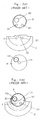
- FIG. 3(a) plan views of these parts are shown.
- Fig. 3(b) a plan view of the assembly of these parts is shown.
- Fig. 4 shows a plan view of assembly of shell-type needle bearing 230 and orbiting scroll 4, as seen from the drive shaft side. It is known to use a thin shell-type needle bearing in order to prevent an increase in the overall thickness of boss 42 of orbiting scroll 4. when assembling, shell-type needle bearing 230 will be pressure inserted into boss 42. However, shell-type needle bearing 230 is structurally weak against external forces. Broken line D indicates a diameter of an enveloping circle which touches every needle bearing. Due to the pressure insertion of shell-type needle bearing 230 into boss 42, the resultant diameter D uncontrollably deviates from its intended value.
- disk-shaped bushing 3 engages within shell-type needle bearing 230.
- the smoothness of the mutual sliding of disk-shaped bushing 3 and shell-type needle bearing 230 greatly affects the lifespan of the compressor. Therefore, it is desired to reduce or prevent any unnecessary stress from existing in shell-type needle bearing 230.
- several kinds of disk-shaped bushings 3, each having slightly different diameters that appropriately fit the actual inner diameter D, are prepared.
- About 8 kinds of disk-shaped bushings are typically produced, each differing by about 5 micrometers in diameter.
- the present invention provides a structure for the swing-link mechanism that reduces the overall number of species of disk-shaped bushings for the scroll-type compressor that must be produced.
- the present invention provides a common disk-shaped bushing that may be used in both the counterclockwise-driven compressor and the clockwise-driven compressor, so that the number of kinds of disk-shaped bushings can be reduced in half.
- a swing-link mechanism of a scroll-type compressor includes a large diameter part that is formed integrally with a drive shaft, a disk-shaped bushing that is engaged rotatably with a crank pin that protrudes from the end surface of the large diameter part.
- the disk-shaped bushing has two rivet holes that are formed therethrough.
- the swing-like mechanism also includes a counterweight that is combined with the disk-shaped bushing by rivets.
- the counterweight has two nvet holes formed therethrough. The two nvet holes that are formed in the disk-shaped bushing are provided at symmetrical positions with respect to a first line that passes through the center of the crank pin hole and a center of the disk-shaped bushing.
- a tongue part that is elongated in an opposite side from the weight body of the counterweight is provided.
- One of the two rivet holes formed in the counterweight is provided in the tongue part.
- a swing-link mechanism of a scroll-type compressor includes a large diameter part that is formed integrally with a drive shaft, a disk-shaped bushing that is engaged rotatably with a crank pin that protrudes from the end surface of the large diameter part, and a counterweight that is combined with the disk-shaped bushing by a plurality of rivets.
- a first lubrication hole is provided in the disk-shaped bushing so that the center of the first lubncation hole lies on a first line that passes through the center of the crank pin hole and the center of the disk-shaped bushing.
- a second lubrication hole is provided in the large diameter part so that the center of the second lubrication hole lies on a second line that passes through the center of the crank pin and the center of the large diameter part.
- a third lubrication hole is provided in the counterweight so that the third lubrication hole overlaps both the first lubrication hole and the second lubrication hole simultaneously in order to establish communication from the first lubncation hole to the second lubrication hole.
- Fig. 1 is a longitudinal cross-sectional view of a known scroll-type compressor.
- Fig. 2 is a perspective view of a known swing-link mechanism.
- Fig. 3(a) is a plan view of the parts constituting the known swing-link mechanism.
- Fig. 3(b) is a plan view of the assembly of the known swing-link mechanism.
- Fig. 4 is a plan view of assembly of an orbiting scroll.
- Fig. 5 is a longitudinal cross-sectional view of a scroll-type compressor according to the present invention.
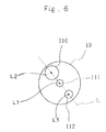
- Fig. 6 is a plan view of large diameter part according to the present invention.
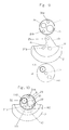
- Fig. 7(a) is a plan view of a counterweight of a clockwise rotational species.
- Fig. 7(b) is a plan view of a counterweight of a counterclockwise rotational species.
- Fig. 8(a) is a plan view of disk-shaped bushing of a clockwise rotational species.
- Fig. 8(b) is a plan view of a disk-shaped bushing of a counterclockwise rotational species, identical to that one shown in Fig. 8(a) .
- Fig. 9 is a plan view of the parts constituting the swing-link mechanism according to the present invention.
- Fig. 10 is a plan view of the assembly of the swing-link mechanism according to the present invention.
- Fig. 11 is an enlarged longitudinal cross-sectional view of the swing-link mechanism according to the present invention.
- FIG. 5 a longitudinal cross-section of a scroll-type compressor equipped with a swing-link mechanism according to the present invention is shown.
- the swing-link mechanism according to the present invention comprises large diameter part 10, counterweight 2, and disk-shaped bushing 3.
- like numbers denote the like parts in Fig. 1, so an explanation of such parts is therefore omitted.
- crank pin 110 is provided crank pin 110, restriction hole 111, and lubrication hole 112. It is designed so that center L2 of crank pin 110 and center L3 of lubrication hole 112 may be aligned on Line L, which passes through center L1 of large diameter part 10. Center of the restriction hole 111 coincides with the center L1 of large diameter part 10.
- Fig. 7(a) and Fig. 7(b) show the clockwise rotational species and the counterclockwise rotational species, respectively, of counterweight 2.
- tongue part 29 At the opposite side to weight body 27 of counterweight 2 is provided tongue part 29.
- nvet holes 21a and 21b are provided at the opposite side to weight body 27 of counterweight 2.
- Line V is defined as a line that passes through center C of protrusion 20, and divides weight body 27 in half.
- lubrication hole 22 is provided at approximately a symmetric position against rivet hole 21b with respect to vertical line V in the figure. The exact position of lubrication hole 22 will be explained later.
- Fig. 8(a) and Fig. 8(b) show the clockwise rotational species and counterclockwise rotational species, respectively, of disk-shaped bushing 3.
- the two disk-shaped bushings are identical to each other. The equality in shape for both species is one of the essences of the present invention.
- Two rivet holes 31a and 31b are disposed at exactly symmetrical positions with respect to line M, which passes through center D2 of crank pin hole 30 and center D1 of disk-shaped bushing 3.
- Lubrication hole 32 is provided such that center D3 of lubrication hole 32 is located on line M. Because of these structures, disk-shaped bushing 3 becomes completely symmetrical with respect to line M; thus disk-shaped busing 3 for either the rotational species shown in Fig.
- Fig. 9 parts of the swing-link mechanism for one rotational species are shown placed side-by-side. As mentioned in above, the only part that requires the production of two rotational species is counterweight 2. Two rivets (not shown) are inserted in rivet holes 31a, 31b of disk-shaped bushing 3 and 21a, 21b of counterweight 2, in order to combine them.
- Protrusion 20 of counterweight 2 engages loosely with restriction hole 111 of large diameter part 10.
- Crank pin 110 of large diameter part 10 engages with crank pin hole 30 of disk-shaped bushing 3, disk-shaped bushing 3 being rotatable with respect to crank pin 110.
- Fig. 10 is the plan view of the assembly of the three parts.
- Lubrication hole 32 of disk-shaped bushing 3 partially overlaps lubrication hole 22 of counterweight 2.
- Lubrication hole 22 of counterweight 2 partially overlaps lubrication hole 112 of large diameter part 10.
- the position of lubrication hole 22 of counterweight 2 may be designed such that lubrication hole 22 partially overlaps both lubrication hole 32 of disk-shaped bushing 3 and lubrication hole 112 of large diameter part 10 simultaneously.
- refrigerant gas is permitted to pass freely from lubrication hole 112 of large diameter part 10 to lubncation hole 32 of disk-shaped bushing 3 via lubrication hole 22 of counterweight 2.
- space R1 is enclosed by oil seal 13 and front housing 100 and large diameter part 10.
- Space R3 is enclosed by front housing 100 and orbiting scroll 4.
- Space R2 is enclosed by recess 33 of disk-shaped bushing 3 and the bottom of boss 42 of orbiting scroll 4.
- the present invention has provided rivet holes symmetrically disposed on the disk-shaped bushing and at the same time, has provided lubrication holes for each of the disk-shaped bushing, the counterweight, and the large diameter part.
Landscapes
- Engineering & Computer Science (AREA)
- Mechanical Engineering (AREA)
- General Engineering & Computer Science (AREA)
- Rotary Pumps (AREA)
Applications Claiming Priority (2)
| Application Number | Priority Date | Filing Date | Title |
|---|---|---|---|
| JP36253897A JPH11182461A (ja) | 1997-12-15 | 1997-12-15 | スクロール型圧縮機 |
| JP36253897 | 1997-12-15 |
Publications (1)
| Publication Number | Publication Date |
|---|---|
| EP0924432A1 true EP0924432A1 (fr) | 1999-06-23 |
Family
ID=18477113
Family Applications (1)
| Application Number | Title | Priority Date | Filing Date |
|---|---|---|---|
| EP98123092A Ceased EP0924432A1 (fr) | 1997-12-15 | 1998-12-10 | Entraínement à excentrique basculant pour un compresseur à spirales |
Country Status (3)
| Country | Link |
|---|---|
| EP (1) | EP0924432A1 (fr) |
| JP (1) | JPH11182461A (fr) |
| AU (1) | AU9711198A (fr) |
Cited By (4)
| Publication number | Priority date | Publication date | Assignee | Title |
|---|---|---|---|---|
| WO2009091868A1 (fr) * | 2008-01-17 | 2009-07-23 | Bitzer Scroll Inc. | Contrepoids monté sur arbre, procédé et compresseur à spirale incorporant celui-ci |
| US9605676B2 (en) | 2013-05-31 | 2017-03-28 | Emerson Climate Technologies, Inc. | Variable speed scroll compressor |
| WO2018019372A1 (fr) * | 2016-07-27 | 2018-02-01 | Bitzer Kühlmaschinenbau Gmbh | Compresseur |
| US20240011487A1 (en) * | 2020-11-24 | 2024-01-11 | Sanden Corporation | Scroll fluid machine |
Families Citing this family (2)
| Publication number | Priority date | Publication date | Assignee | Title |
|---|---|---|---|---|
| JP5631355B2 (ja) * | 2012-05-07 | 2014-11-26 | 三菱重工業株式会社 | スクロール圧縮機 |
| JP7056820B2 (ja) * | 2018-06-29 | 2022-04-19 | サンデン・オートモーティブコンポーネント株式会社 | スクロール圧縮機 |
Citations (2)
| Publication number | Priority date | Publication date | Assignee | Title |
|---|---|---|---|---|
| EP0052461A1 (fr) * | 1980-11-10 | 1982-05-26 | Sanden Corporation | Appareil à déplacement de fluide à volutes imbriquées ayant des moyens pour compenser des forces centrifuges |
| EP0806570A1 (fr) * | 1996-05-10 | 1997-11-12 | Sanden Corporation | Appareil de déplacement des fluides à spirales |
-
1997
- 1997-12-15 JP JP36253897A patent/JPH11182461A/ja active Pending
-
1998
- 1998-12-10 EP EP98123092A patent/EP0924432A1/fr not_active Ceased
- 1998-12-14 AU AU97111/98A patent/AU9711198A/en not_active Abandoned
Patent Citations (2)
| Publication number | Priority date | Publication date | Assignee | Title |
|---|---|---|---|---|
| EP0052461A1 (fr) * | 1980-11-10 | 1982-05-26 | Sanden Corporation | Appareil à déplacement de fluide à volutes imbriquées ayant des moyens pour compenser des forces centrifuges |
| EP0806570A1 (fr) * | 1996-05-10 | 1997-11-12 | Sanden Corporation | Appareil de déplacement des fluides à spirales |
Cited By (8)
| Publication number | Priority date | Publication date | Assignee | Title |
|---|---|---|---|---|
| WO2009091868A1 (fr) * | 2008-01-17 | 2009-07-23 | Bitzer Scroll Inc. | Contrepoids monté sur arbre, procédé et compresseur à spirale incorporant celui-ci |
| US7967581B2 (en) | 2008-01-17 | 2011-06-28 | Bitzer Kuhlmaschinenbau Gmbh | Shaft mounted counterweight, method and scroll compressor incorporating same |
| CN101952550B (zh) * | 2008-01-17 | 2014-03-12 | 比策尔制冷机械制造有限公司 | 安装在轴上的配重、方法和包含配重的涡旋压缩机 |
| US8672654B2 (en) | 2008-01-17 | 2014-03-18 | Bitzer Kuhlmaschinenbau Gmbh | Shaft mounted counterweight, method and scroll compressor incorporating same |
| US9605676B2 (en) | 2013-05-31 | 2017-03-28 | Emerson Climate Technologies, Inc. | Variable speed scroll compressor |
| WO2018019372A1 (fr) * | 2016-07-27 | 2018-02-01 | Bitzer Kühlmaschinenbau Gmbh | Compresseur |
| US11326593B2 (en) | 2016-07-27 | 2022-05-10 | Bitzer Kuehlmaschinenbau Gmbh | Scroll compressor orbital path balancing mass |
| US20240011487A1 (en) * | 2020-11-24 | 2024-01-11 | Sanden Corporation | Scroll fluid machine |
Also Published As
| Publication number | Publication date |
|---|---|
| AU9711198A (en) | 1999-07-01 |
| JPH11182461A (ja) | 1999-07-06 |
Similar Documents
| Publication | Publication Date | Title |
|---|---|---|
| KR101480970B1 (ko) | 리테이닝 기구를 가진 압축기 | |
| US7344365B2 (en) | Scroll compressor with bypass holes communicating with an intake chamber | |
| US7736136B2 (en) | Compressor including separation tube engagement mechanism | |
| US5931650A (en) | Hermetic electric scroll compressor having a lubricating passage in the orbiting scroll | |
| KR20210027108A (ko) | 전동 압축기 | |
| KR970003266B1 (ko) | 내부윤활유 펌프를 갖춘 수평방향 회전장치 | |
| JP2002005022A (ja) | 圧縮機 | |
| KR20030075179A (ko) | 수평 스크롤 압축기 | |
| KR102443952B1 (ko) | 전동 압축기 | |
| JPH04231697A (ja) | 回転滑り弁形真空ポンプ | |
| EP0924432A1 (fr) | Entraínement à excentrique basculant pour un compresseur à spirales | |
| US20060171830A1 (en) | Scroll type hydraulic machine | |
| US6179591B1 (en) | Conical hub bearing for scroll machine | |
| US6599110B2 (en) | Scroll-type compressor with lubricant provision | |
| US5141422A (en) | Scroll-type compressor having cooling and lubrication holes to various mechanisms | |
| WO2018012411A1 (fr) | Compresseur de fluide frigorigène de type ouvert | |
| US5120205A (en) | Scroll type compressor with improved bearing arrangement for drive shaft | |
| US20020009248A1 (en) | Compressor bearings | |
| US20060171831A1 (en) | Scroll machine | |
| KR20250170696A (ko) | 스크롤형 압축기 | |
| KR100359358B1 (ko) | 압축기의 전자 클러치 구조 | |
| JP3031297B2 (ja) | スクロール圧縮機 | |
| US20180038372A1 (en) | Rotating cylinder type compressor | |
| US5660538A (en) | Suction mechanism of a fluid displacement apparatus | |
| JPH08210274A (ja) | スクロール型圧縮機 |
Legal Events
| Date | Code | Title | Description |
|---|---|---|---|
| PUAI | Public reference made under article 153(3) epc to a published international application that has entered the european phase |
Free format text: ORIGINAL CODE: 0009012 |
|
| AK | Designated contracting states |
Kind code of ref document: A1 Designated state(s): DE FR |
|
| AX | Request for extension of the european patent |
Free format text: AL;LT;LV;MK;RO;SI |
|
| 17P | Request for examination filed |
Effective date: 19990616 |
|
| AKX | Designation fees paid |
Free format text: DE FR |
|
| 17Q | First examination report despatched |
Effective date: 20000306 |
|
| GRAG | Despatch of communication of intention to grant |
Free format text: ORIGINAL CODE: EPIDOS AGRA |
|
| STAA | Information on the status of an ep patent application or granted ep patent |
Free format text: STATUS: THE APPLICATION HAS BEEN REFUSED |
|
| 18R | Application refused |
Effective date: 20010216 |