EP0924441A1 - Articulation à rotule et procédé pour la précontraindre - Google Patents
Articulation à rotule et procédé pour la précontraindre Download PDFInfo
- Publication number
- EP0924441A1 EP0924441A1 EP98122313A EP98122313A EP0924441A1 EP 0924441 A1 EP0924441 A1 EP 0924441A1 EP 98122313 A EP98122313 A EP 98122313A EP 98122313 A EP98122313 A EP 98122313A EP 0924441 A1 EP0924441 A1 EP 0924441A1
- Authority
- EP
- European Patent Office
- Prior art keywords
- housing
- bearing shell
- closure element
- ball joint
- joint according
- Prior art date
- Legal status (The legal status is an assumption and is not a legal conclusion. Google has not performed a legal analysis and makes no representation as to the accuracy of the status listed.)
- Withdrawn
Links
- 238000000034 method Methods 0.000 title claims abstract description 15
- 230000000295 complement effect Effects 0.000 claims abstract description 17
- 230000036316 preload Effects 0.000 claims description 30
- 238000003466 welding Methods 0.000 claims description 12
- 239000000725 suspension Substances 0.000 claims description 2
- 230000000284 resting effect Effects 0.000 claims 1
- 238000004519 manufacturing process Methods 0.000 description 3
- 230000015572 biosynthetic process Effects 0.000 description 2
- 206010023230 Joint stiffness Diseases 0.000 description 1
- 238000010276 construction Methods 0.000 description 1
- 230000000694 effects Effects 0.000 description 1
- 230000001771 impaired effect Effects 0.000 description 1
- 238000003780 insertion Methods 0.000 description 1
- 230000037431 insertion Effects 0.000 description 1
- 238000007789 sealing Methods 0.000 description 1
- 238000003860 storage Methods 0.000 description 1
Images


Classifications
-
- B—PERFORMING OPERATIONS; TRANSPORTING
- B23—MACHINE TOOLS; METAL-WORKING NOT OTHERWISE PROVIDED FOR
- B23P—METAL-WORKING NOT OTHERWISE PROVIDED FOR; COMBINED OPERATIONS; UNIVERSAL MACHINE TOOLS
- B23P11/00—Connecting or disconnecting metal parts or objects by metal-working techniques not otherwise provided for
- B23P11/005—Connecting or disconnecting metal parts or objects by metal-working techniques not otherwise provided for by expanding or crimping
-
- F—MECHANICAL ENGINEERING; LIGHTING; HEATING; WEAPONS; BLASTING
- F16—ENGINEERING ELEMENTS AND UNITS; GENERAL MEASURES FOR PRODUCING AND MAINTAINING EFFECTIVE FUNCTIONING OF MACHINES OR INSTALLATIONS; THERMAL INSULATION IN GENERAL
- F16C—SHAFTS; FLEXIBLE SHAFTS; ELEMENTS OR CRANKSHAFT MECHANISMS; ROTARY BODIES OTHER THAN GEARING ELEMENTS; BEARINGS
- F16C11/00—Pivots; Pivotal connections
- F16C11/04—Pivotal connections
- F16C11/06—Ball-joints; Other joints having more than one degree of angular freedom, i.e. universal joints
- F16C11/0619—Ball-joints; Other joints having more than one degree of angular freedom, i.e. universal joints the female part comprising a blind socket receiving the male part
- F16C11/0623—Construction or details of the socket member
- F16C11/0628—Construction or details of the socket member with linings
-
- F—MECHANICAL ENGINEERING; LIGHTING; HEATING; WEAPONS; BLASTING
- F16—ENGINEERING ELEMENTS AND UNITS; GENERAL MEASURES FOR PRODUCING AND MAINTAINING EFFECTIVE FUNCTIONING OF MACHINES OR INSTALLATIONS; THERMAL INSULATION IN GENERAL
- F16C—SHAFTS; FLEXIBLE SHAFTS; ELEMENTS OR CRANKSHAFT MECHANISMS; ROTARY BODIES OTHER THAN GEARING ELEMENTS; BEARINGS
- F16C11/00—Pivots; Pivotal connections
- F16C11/04—Pivotal connections
- F16C11/06—Ball-joints; Other joints having more than one degree of angular freedom, i.e. universal joints
- F16C11/0619—Ball-joints; Other joints having more than one degree of angular freedom, i.e. universal joints the female part comprising a blind socket receiving the male part
- F16C11/0623—Construction or details of the socket member
- F16C11/0647—Special features relating to adjustment for wear or play; Wear indicators
-
- F—MECHANICAL ENGINEERING; LIGHTING; HEATING; WEAPONS; BLASTING
- F16—ENGINEERING ELEMENTS AND UNITS; GENERAL MEASURES FOR PRODUCING AND MAINTAINING EFFECTIVE FUNCTIONING OF MACHINES OR INSTALLATIONS; THERMAL INSULATION IN GENERAL
- F16C—SHAFTS; FLEXIBLE SHAFTS; ELEMENTS OR CRANKSHAFT MECHANISMS; ROTARY BODIES OTHER THAN GEARING ELEMENTS; BEARINGS
- F16C11/00—Pivots; Pivotal connections
- F16C11/04—Pivotal connections
- F16C11/06—Ball-joints; Other joints having more than one degree of angular freedom, i.e. universal joints
- F16C11/0685—Manufacture of ball-joints and parts thereof, e.g. assembly of ball-joints
- F16C11/069—Manufacture of ball-joints and parts thereof, e.g. assembly of ball-joints with at least one separate part to retain the ball member in the socket; Quick-release systems
-
- F—MECHANICAL ENGINEERING; LIGHTING; HEATING; WEAPONS; BLASTING
- F16—ENGINEERING ELEMENTS AND UNITS; GENERAL MEASURES FOR PRODUCING AND MAINTAINING EFFECTIVE FUNCTIONING OF MACHINES OR INSTALLATIONS; THERMAL INSULATION IN GENERAL
- F16C—SHAFTS; FLEXIBLE SHAFTS; ELEMENTS OR CRANKSHAFT MECHANISMS; ROTARY BODIES OTHER THAN GEARING ELEMENTS; BEARINGS
- F16C25/00—Bearings for exclusively rotary movement adjustable for wear or play
- F16C25/02—Sliding-contact bearings
-
- B—PERFORMING OPERATIONS; TRANSPORTING
- B23—MACHINE TOOLS; METAL-WORKING NOT OTHERWISE PROVIDED FOR
- B23P—METAL-WORKING NOT OTHERWISE PROVIDED FOR; COMBINED OPERATIONS; UNIVERSAL MACHINE TOOLS
- B23P2700/00—Indexing scheme relating to the articles being treated, e.g. manufactured, repaired, assembled, connected or other operations covered in the subgroups
- B23P2700/11—Joints, e.g. ball joints, universal joints
-
- B—PERFORMING OPERATIONS; TRANSPORTING
- B60—VEHICLES IN GENERAL
- B60G—VEHICLE SUSPENSION ARRANGEMENTS
- B60G2204/00—Indexing codes related to suspensions per se or to auxiliary parts
- B60G2204/40—Auxiliary suspension parts; Adjustment of suspensions
- B60G2204/416—Ball or spherical joints
Definitions
- the present invention relates to a ball joint, in particular for parts of steering or wheel suspension of motor vehicles, with the features of the preamble of claim 1, and a procedure for its prestressing with the characteristics of Preamble of claim 16.
- the object of the invention is therefore to create a ball joint, in which a preload of the ball head with respect its storage in a simple manner with a required accuracy is adjustable.
- the invention it is now possible to largely pre-tension independent of the dimensions and tolerances of the individual parts and to fix it permanently during assembly.
- the individual tolerances can be widened considerably, which means a much more cost-effective production of the individual parts is made possible.
- the effect of tolerances on the ball joint is greatly reduced, the quality of the manufactured Ball joints can be improved in a simple manner.
- the preload the ball joint can be largely independent of the dimensions of the individual parts directly over the on the Closing element of the ball joint applied preload can be set.
- the closure element and the bearing shell and / or the bearing shell and the housing with opposite, complementary cone-like Sections trained.
- a pretensioning force acting in the direction of the journal or the axial direction on the closure element in the perpendicular to this radial direction redirected so that in addition to the axial preload the radial position of the ball head is also determined.
- This makes it possible to use radial as well as axial ones Compensate tolerances of the components, so that these radial tolerances can be expanded, making a less expensive Manufacturing is possible. Due to the redirection of force is one Production of joints with improved quality possible because the influences of radial tolerances due to the axial locking can be influenced.
- the complementary, conical sections are expedient of closure element and housing and / or bearing shell and housing formed with slightly different taper angles. This ensures on the one hand that the investment area between the closure element and the bearing shell if possible is close to the pivot pin, and on the other hand that an optimal The preload can be distributed over the entire bearing shell is.
- This game can be used radial determination of the bearing shell when exposed to an axial Power can be used. It also facilitates during the Assemble the axial insertion of the bearing shell into the housing.
- closure element and the bearing shell and / or the bearing shell and the housing with opposite, complementary, essentially spherical shell-shaped sections.
- the spherical shell Sections formed with different radii of curvature are.
- the tolerance requirements for the housing and Bearing shell relatively low, as a bearing shell with something smaller radius of curvature due to axial or radial preload optimal to a larger radius of curvature of the housing can be adjusted.
- the bearing shell is expediently in the region of its equatorial one Inside diameter with an annular recess This means that the tolerance requirements are met Ball head and bearing shell reduced compared to conventional systems. Furthermore, the wear of the ball joint in this Range can be influenced favorably.
- the bearing shell in its bottom area is formed on the inside with a recess.
- the bearing shell is expediently in one of the pivot pins facing area formed with a number of slots, making the assembly of the joint easier.
- the bearing shell with a housing facing protruding area is formed, which in a engages complementarily shaped area of the housing.
- the location of the bearing shell within the housing in easier and be fixed reliably.
- the closure element for fixing the Articulated preload can be moved on the housing using the play feasible and on any of the to be set Preload corresponding position can be fixed.
- an area can be specified in a simple manner, within which adjustment of the preload is possible.
- the closure element is expediently by means of welding, especially laser welding fixable on the housing.
- the fixation using laser welding is compared to conventional fixing methods to carry out in a very simple and inexpensive manner.
- the fixation by means of laser welding also reduces the required space and thus enables space-saving construction.
- the closure element by deformation of the housing, in particular by squeezing the housing walls perpendicular to the axial Preload direction, fixable on the housing.
- Process for deforming the housing For example it is possible to bolt the housing walls using bolts that a sufficient force for the deformation in several places of the circumference are encountered on the housing wall. This results in a low plastic deformation the housing while connecting the housing to the Closure element.
- fixation a flanging tool to perform, for example by moving in the direction of the preload the side of the housing presses against the closure element and thus permanently fixed.
- It is also possible to carry out the fixation by means of clamping jaws, the housing with sufficient force to the closure element press.
- the housing is only minimal Dimensions plastically deformed.
- the closure element is expediently on its outer Circumferential surface and / or the inner wall area interacting with it of the housing with sawtooth-like or triangular Grooves or projections formed. This is when squeezing the housing wall a positive connection of Housing and cover can be achieved. Through the grooves or Protrusions ensure that the closure element not changed in diameter, because the groove tips high forces can give in.
- the joint essentially exists from a housing 1, one in a recess 6 of the Housing 1 accommodated bearing shell 2, a pivot pin 7 with ball head 3 and a closure element 4.
- Usual sealing devices, especially bellows, are for the not relevant to the present invention and therefore not shown.
- the bearing shell 2 has the bottom of the recess 6 of the housing facing wall area one to this Wall area complementary conical taper 2a. Subsequently the bearing shell 2 on the outside of this area 2a Wall area a middle, cylindrical section 2d as well another conically tapering upper section 2c.
- closure element 4 is formed.
- the closure element 4 lies with a conical surface 4c on the top conical section 2c of the bearing shell 2.
- the closure element 4 is in the pin axis direction, i.e. in the Exemplary embodiments shown in the direction of that in FIG. 1 shown arrows F, slidably used in the housing 1.
- the housing recess 6 has an upper, with an enlarged diameter formed area 6a.
- On the inner wall 1a of this area 6a is the closure element 4 slidably guided with its outer wall 4a.
- the housing 1 is also formed with a shoulder 1b through which the displaceability of the closure element 4 is limited. Between the shoulder area 1b and one opposite this area Wall 4b of the closure element 4 is a game intended. The displaceability of the closure element 4 relative to the case is therefore determined by the size of this game.
- the ball joint Preload force evenly in the direction of the pin axis to realize force F applied to the closure element 4.
- the direction of the force F is shown in the figures by the arrows already mentioned. It is important to ensure that the locking element or the locking ring 4 in the area the desired preload with the housing, in illustrated embodiment thus the shoulder area 1b, comes into play. By choosing the height of the shoulder area 1b and the resulting game between this shoulder area 1b and the lower surface 4b of the closure element an adjustable preload range can be defined.
- the biasing force F acts on the bearing shell 2 and thus the ball head 3.
- the is evenly on the Closure element 4 applied force F to the bearing shell 2 and transfer the ball head 3, whereby the desired biasing force is adjustable in the ball joint.
- bearing shell 2 and housing 1 are matched to one another in this case, that the bearing shell 2 between the ball head and the housing 1st or the closure element 4 with a desired friction torque determining bias is maintained, which is preferred is chosen such that the only indicated Hinge pin 7 is pivotable without breakaway torque.
- the tolerance requirements for the individual components are here because of the force-related realization of the preload less than with conventional ball joints.
- the procedure is basically applicable to all ball joints, in which a closure element in the pin axis direction in to be fixed to the housing.
- FIGS. 2 and 3 correspond essentially that already described, in FIG. 1 illustrated embodiment.
- the same components are included here the same reference numerals.
- the embodiment of Figure 2 differs from that of Figure 1 in that the closure element 4 on the Hinge pin 7 arranged opposite side of the joint is. Furthermore, the closure element 4 is lid-shaped.
- closure element 4 an annular extension 4e, which itself in an area between the housing 1 and the bearing shell 2 extends.
- the closure element 4 is on the the hinge pin 7 opposite side of the hinge lid-shaped educated.
- the bearing shell 2 is on the outside with two lower, each other adjoining conical areas 2a, 2b with different Conicity angles formed which are complementary molded sections of the housing 1 abut.
- the opposite sections of Bearing shell and housing slightly different inclination or Conicity angle on, as for area 2a in the figure 4 is shown explicitly.
- By providing this angular play between housing 1 and bearing shell 2 is the introduction of the bearing shell 2 simplified into the housing during assembly.
- Preload larger component tolerances are accepted.
- the complementary conical bearing surfaces 4c, 2c of Closure element 4 and bearing shell 2 are slightly different Conicity angles formed, which also means here Larger component tolerances are possible.
- the bearing shell 2 is with a protruding area 11 formed into a complementary shaped recess 12 of the housing 1 engages. Furthermore, the Bearing shell to simplify the assembly of the ball head in the upper area evenly around the circumference in some places formed with slots 20.
- the bearing shell 2 inside in the area of the equatorial diameter 30 of the spherical head an annular recess 10, and in her Bottom area a further recess 21. With preload the bearing shell 2 is thereby ensured that the Kugekkopf in these recess areas not on the bearing shell rests, which can reduce wear.
- FIGS Various methods are shown schematically in FIGS for fixing or jamming the closure element 4 on the housing 1 shown.
- the same components are the same Provide reference numerals.
- the jamming serves to fix a position of the closure element 4, which the desired preload in the ball joint corresponds. This is how the pretension path is, as already explained not depending on the geometric dimensions of the Components, but realized by the selected preload.
- the fixation is carried out by means of bolts 40, which are pressed or pushed against the wall of the housing 1 with a sufficient force F Fix at several points along the circumference thereof. This causes a slight plastic deformation of the housing 1, which leads to a fixation of the position shell 2 on the housing 1.
- the formation of the closure element with triangular grooves 42 enables a positive connection between the housing and the closure element.
- the grooves 42 also ensure that the closure element does not change in its diameter, since the groove tips can yield to high forces.
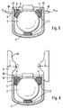
- FIG. 6 shows a fixation by means of a flanging tool 44, which comes from above the housing wall laterally to the closure element 4 presses and thus permanently fixed.
- the illustrated Flaring tool 44 is designed such that the fixation an axial closing of the ball joint by means of flanging the upper sections 46 of the housing wall can follow. Also here is due to the geometric design of the closure element 4 a positive connection.
- FIG. 7 shows a top view of the ball joint according to FIG. 7.
- clamping jaws 50 are provided as an example.
- the housing is plastically deformed by the action of forces F Fix via the clamping jaws 50 and, due to the grooves on the closure element, is connected to it in a form-fitting manner.
- Flanging is an advantage. It is important to ensure that the location of the closure element 4 by the flanging process is changed.
Landscapes
- Engineering & Computer Science (AREA)
- General Engineering & Computer Science (AREA)
- Mechanical Engineering (AREA)
- Pivots And Pivotal Connections (AREA)
- Steering-Linkage Mechanisms And Four-Wheel Steering (AREA)
Applications Claiming Priority (2)
| Application Number | Priority Date | Filing Date | Title |
|---|---|---|---|
| DE19756984 | 1997-12-20 | ||
| DE1997156984 DE19756984A1 (de) | 1997-12-20 | 1997-12-20 | Kugelgelenk und Verfahren zu seiner Vorspannung |
Publications (1)
| Publication Number | Publication Date |
|---|---|
| EP0924441A1 true EP0924441A1 (fr) | 1999-06-23 |
Family
ID=7852811
Family Applications (1)
| Application Number | Title | Priority Date | Filing Date |
|---|---|---|---|
| EP98122313A Withdrawn EP0924441A1 (fr) | 1997-12-20 | 1998-11-24 | Articulation à rotule et procédé pour la précontraindre |
Country Status (2)
| Country | Link |
|---|---|
| EP (1) | EP0924441A1 (fr) |
| DE (1) | DE19756984A1 (fr) |
Cited By (9)
| Publication number | Priority date | Publication date | Assignee | Title |
|---|---|---|---|---|
| RU2149289C1 (ru) * | 1999-10-25 | 2000-05-20 | Закрытое акционерное общество Научно-производственное объединение "БелМаг" | Шаровой шарнир |
| WO2004083660A1 (fr) * | 2003-03-18 | 2004-09-30 | Kongsberg Automotive Asa | Dispositif a joint a rotule |
| WO2005124169A1 (fr) * | 2004-06-18 | 2005-12-29 | Zf Friedrichshafen Ag | Articulation centrale pour levier triangulaire de vehicules a moteur |
| WO2006018004A1 (fr) * | 2004-08-19 | 2006-02-23 | Zf Friedrichshafen Ag | Articulation a rotule et procede pour sa production |
| WO2008083808A2 (fr) | 2007-01-12 | 2008-07-17 | Trw Automotive Gmbh | Joint sphérique |
| EP1967323A3 (fr) * | 2007-03-08 | 2009-07-15 | BESSEY Tool GmbH & Co. KG | Dispositif pour appliquer une pression sur une pièce de travail |
| US11396906B2 (en) * | 2018-07-18 | 2022-07-26 | Federal-Mogul Motorparts, LLC | Ball socket assembly with a preload bearing |
| DE102022003676A1 (de) | 2022-10-05 | 2024-04-11 | Mercedes-Benz Group AG | Kugelgelenk für ein Fahrwerk eines Fahrzeugs, insbesondere eines Kraftfahrzeugs |
| WO2024224781A1 (fr) * | 2023-04-27 | 2024-10-31 | 株式会社ソミックマネージメントホールディングス | Procédé de fabrication de joint à rotule |
Families Citing this family (9)
| Publication number | Priority date | Publication date | Assignee | Title |
|---|---|---|---|---|
| DE102004040412B4 (de) | 2004-08-19 | 2006-12-14 | Zf Friedrichshafen Ag | Kugelhülsengelenk und Verfahren zu dessen Herstellung |
| DE102005060719A1 (de) * | 2005-12-19 | 2007-06-21 | Siemens Ag | Verfahren zum Verstemmen eines ersten Teiles |
| DE102006008250A1 (de) | 2006-02-22 | 2007-08-23 | Trw Automotive Gmbh | Kugelgelenk |
| DE102006024198A1 (de) * | 2006-05-23 | 2007-12-27 | Trw Automotive Gmbh | Verfahren zur Herstellung eines Kugelgelenks sowie Kugelgelenk |
| DE102006043930B4 (de) * | 2006-09-14 | 2009-08-13 | Zf Friedrichshafen Ag | Kugelgelenk |
| DE102011114204A1 (de) | 2011-09-23 | 2012-11-29 | Daimler Ag | Kugelgelenk und Verfahren zu dessen Montage |
| DE102013105091A1 (de) | 2013-05-17 | 2014-11-20 | Benteler Automobiltechnik Gmbh | Kugelgelenk und Kraftfahrzeug-Lenker |
| WO2020085138A1 (fr) * | 2018-10-24 | 2020-04-30 | 日本発條株式会社 | Structure de fixation de feuille de bille pour joint à rotule |
| JP7228449B2 (ja) * | 2018-10-24 | 2023-02-24 | 日本発條株式会社 | ボールジョイントのボールシート固定構造 |
Citations (6)
| Publication number | Priority date | Publication date | Assignee | Title |
|---|---|---|---|---|
| DE1922123A1 (de) * | 1968-05-06 | 1969-11-13 | Gen Motors Corp | Verfahren zum Herstellen von Kugelgelenken fuer den Kraftfahrzeugbau |
| US3950006A (en) * | 1972-09-11 | 1976-04-13 | Trw Inc. | Rack and pinion steering assembly |
| US4163617A (en) * | 1977-02-14 | 1979-08-07 | Musashisemitsukoguo Kabushikikaisha | Ball joint |
| FR2446694A1 (fr) * | 1979-01-17 | 1980-08-14 | Dba | Procede d'assemblage d'articulation a rotule |
| FR2498494A1 (fr) * | 1981-01-23 | 1982-07-30 | Dba | Procede et appareil pour la fabrication d'une rotule et rotule ainsi obtenue |
| EP0342351A1 (fr) * | 1988-05-14 | 1989-11-23 | TRW Ehrenreich GmbH & Co. KG | Articulation à rotule |
Family Cites Families (1)
| Publication number | Priority date | Publication date | Assignee | Title |
|---|---|---|---|---|
| DE19513826C1 (de) * | 1995-04-12 | 1996-07-04 | Trw Fahrwerksyst Gmbh & Co | Kugelgelenk |
-
1997
- 1997-12-20 DE DE1997156984 patent/DE19756984A1/de not_active Withdrawn
-
1998
- 1998-11-24 EP EP98122313A patent/EP0924441A1/fr not_active Withdrawn
Patent Citations (6)
| Publication number | Priority date | Publication date | Assignee | Title |
|---|---|---|---|---|
| DE1922123A1 (de) * | 1968-05-06 | 1969-11-13 | Gen Motors Corp | Verfahren zum Herstellen von Kugelgelenken fuer den Kraftfahrzeugbau |
| US3950006A (en) * | 1972-09-11 | 1976-04-13 | Trw Inc. | Rack and pinion steering assembly |
| US4163617A (en) * | 1977-02-14 | 1979-08-07 | Musashisemitsukoguo Kabushikikaisha | Ball joint |
| FR2446694A1 (fr) * | 1979-01-17 | 1980-08-14 | Dba | Procede d'assemblage d'articulation a rotule |
| FR2498494A1 (fr) * | 1981-01-23 | 1982-07-30 | Dba | Procede et appareil pour la fabrication d'une rotule et rotule ainsi obtenue |
| EP0342351A1 (fr) * | 1988-05-14 | 1989-11-23 | TRW Ehrenreich GmbH & Co. KG | Articulation à rotule |
Cited By (14)
| Publication number | Priority date | Publication date | Assignee | Title |
|---|---|---|---|---|
| RU2149289C1 (ru) * | 1999-10-25 | 2000-05-20 | Закрытое акционерное общество Научно-производственное объединение "БелМаг" | Шаровой шарнир |
| WO2004083660A1 (fr) * | 2003-03-18 | 2004-09-30 | Kongsberg Automotive Asa | Dispositif a joint a rotule |
| WO2005124169A1 (fr) * | 2004-06-18 | 2005-12-29 | Zf Friedrichshafen Ag | Articulation centrale pour levier triangulaire de vehicules a moteur |
| WO2006018004A1 (fr) * | 2004-08-19 | 2006-02-23 | Zf Friedrichshafen Ag | Articulation a rotule et procede pour sa production |
| DE102004040403A1 (de) * | 2004-08-19 | 2006-03-09 | Zf Friedrichshafen Ag | Kugelgelenk und Verfahren zu dessen Herstellung |
| WO2008083808A3 (fr) * | 2007-01-12 | 2008-08-28 | Trw Automotive Gmbh | Joint sphérique |
| WO2008083808A2 (fr) | 2007-01-12 | 2008-07-17 | Trw Automotive Gmbh | Joint sphérique |
| US8734044B2 (en) | 2007-01-12 | 2014-05-27 | Trw Automotive Gmbh | Ball joint with an elastic bearing shell |
| KR101420204B1 (ko) * | 2007-01-12 | 2014-07-17 | 티알더블유 오토모티브 게엠베하 | 볼 조인트 |
| EP1967323A3 (fr) * | 2007-03-08 | 2009-07-15 | BESSEY Tool GmbH & Co. KG | Dispositif pour appliquer une pression sur une pièce de travail |
| US8267389B2 (en) | 2007-03-08 | 2012-09-18 | Bessey Tool Gmbh & Co. Kg | Device for applying pressure to a workpiece |
| US11396906B2 (en) * | 2018-07-18 | 2022-07-26 | Federal-Mogul Motorparts, LLC | Ball socket assembly with a preload bearing |
| DE102022003676A1 (de) | 2022-10-05 | 2024-04-11 | Mercedes-Benz Group AG | Kugelgelenk für ein Fahrwerk eines Fahrzeugs, insbesondere eines Kraftfahrzeugs |
| WO2024224781A1 (fr) * | 2023-04-27 | 2024-10-31 | 株式会社ソミックマネージメントホールディングス | Procédé de fabrication de joint à rotule |
Also Published As
| Publication number | Publication date |
|---|---|
| DE19756984A1 (de) | 1999-07-08 |
Similar Documents
| Publication | Publication Date | Title |
|---|---|---|
| EP0924441A1 (fr) | Articulation à rotule et procédé pour la précontraindre | |
| EP3445980B1 (fr) | Articulation à rotule axiale et bras de suspension articulé en deux points à longueur réglable comprenant une telle articulation à rotule axiale | |
| DE19755020B4 (de) | Axialgelenk | |
| EP0836018B1 (fr) | Joint à rotule et procédé de montage | |
| EP0778421A1 (fr) | Joint à rotule | |
| DE4209835A1 (de) | Kugelverbindung | |
| EP2803512B1 (fr) | Articulation à bille et bielle de véhicule automobile | |
| WO2024193756A1 (fr) | Dispositif de commande | |
| DE102008042281A1 (de) | Wellenlagerung in einem Lenksystem und damit ausgestattetes Lenkgetriebe sowie Verfahren zur Herstellung einer Halterung dafür | |
| EP0348642A1 (fr) | Joint à rotule | |
| EP3601013B1 (fr) | Colonne de direction adjustable pour véhicule | |
| EP1676038B1 (fr) | Palier è rotulé servant notamment au centrage mutuel de deux extrimités d'abres | |
| EP1456544A1 (fr) | Articulation spherique | |
| EP1453721A1 (fr) | Support de pivot de fusee | |
| DE69931693T2 (de) | Halter für ein Gleichlaufgelenk | |
| EP0600227B1 (fr) | Charnière à rotule pour portières de voitures | |
| DE69404940T2 (de) | Einrichtung zum Festsetzen einer Schraube zur Steuerung der Neigung eines Scheinwerferreflektors | |
| EP1681478B1 (fr) | Articulation à rotule | |
| DE10159037B4 (de) | Verstelleinrichtung für Kraftfahrzeugsitze | |
| WO2006018004A1 (fr) | Articulation a rotule et procede pour sa production | |
| DE10163147A1 (de) | Kugelgelenk | |
| DE102023201943A1 (de) | Kugelgelenk für ein stangenförmiges Fahrwerkbauteil eines Nutzfahrzeugs | |
| DE3714067C2 (fr) | ||
| DE19832144C2 (de) | Drehpunktlagerung |
Legal Events
| Date | Code | Title | Description |
|---|---|---|---|
| PUAI | Public reference made under article 153(3) epc to a published international application that has entered the european phase |
Free format text: ORIGINAL CODE: 0009012 |
|
| AK | Designated contracting states |
Kind code of ref document: A1 Designated state(s): DE ES FR GB IT |
|
| AX | Request for extension of the european patent |
Free format text: AL;LT;LV;MK;RO;SI |
|
| 17P | Request for examination filed |
Effective date: 19990506 |
|
| AKX | Designation fees paid |
Free format text: DE ES FR GB IT |
|
| STAA | Information on the status of an ep patent application or granted ep patent |
Free format text: STATUS: THE APPLICATION HAS BEEN WITHDRAWN |
|
| 18W | Application withdrawn |
Withdrawal date: 20001209 |