EP0924474A2 - Luftaustritt für Belüftungsanlagen - Google Patents
Luftaustritt für Belüftungsanlagen Download PDFInfo
- Publication number
- EP0924474A2 EP0924474A2 EP98123339A EP98123339A EP0924474A2 EP 0924474 A2 EP0924474 A2 EP 0924474A2 EP 98123339 A EP98123339 A EP 98123339A EP 98123339 A EP98123339 A EP 98123339A EP 0924474 A2 EP0924474 A2 EP 0924474A2
- Authority
- EP
- European Patent Office
- Prior art keywords
- air
- flow
- air outlet
- outlet according
- exit
- Prior art date
- Legal status (The legal status is an assumption and is not a legal conclusion. Google has not performed a legal analysis and makes no representation as to the accuracy of the status listed.)
- Granted
Links
- 238000009423 ventilation Methods 0.000 title claims description 8
- 239000003380 propellant Substances 0.000 claims description 22
- 230000035515 penetration Effects 0.000 claims description 9
- 230000008859 change Effects 0.000 claims description 6
- 230000005764 inhibitory process Effects 0.000 claims 1
- 230000004048 modification Effects 0.000 description 6
- 238000012986 modification Methods 0.000 description 6
- 230000001141 propulsive effect Effects 0.000 description 3
- 230000008901 benefit Effects 0.000 description 2
- 238000007664 blowing Methods 0.000 description 2
- 238000006073 displacement reaction Methods 0.000 description 2
- 230000000694 effects Effects 0.000 description 2
- 230000036961 partial effect Effects 0.000 description 2
- 230000002829 reductive effect Effects 0.000 description 2
- 230000001133 acceleration Effects 0.000 description 1
- 230000015572 biosynthetic process Effects 0.000 description 1
- 238000006243 chemical reaction Methods 0.000 description 1
- 239000003795 chemical substances by application Substances 0.000 description 1
- 238000010276 construction Methods 0.000 description 1
- 230000018109 developmental process Effects 0.000 description 1
- 230000012447 hatching Effects 0.000 description 1
- 230000002401 inhibitory effect Effects 0.000 description 1
- 238000009434 installation Methods 0.000 description 1
- 230000009467 reduction Effects 0.000 description 1
- 230000008439 repair process Effects 0.000 description 1
- 230000002441 reversible effect Effects 0.000 description 1
- 230000007704 transition Effects 0.000 description 1
- 238000011144 upstream manufacturing Methods 0.000 description 1
Images


Classifications
-
- F—MECHANICAL ENGINEERING; LIGHTING; HEATING; WEAPONS; BLASTING
- F24—HEATING; RANGES; VENTILATING
- F24F—AIR-CONDITIONING; AIR-HUMIDIFICATION; VENTILATION; USE OF AIR CURRENTS FOR SCREENING
- F24F13/00—Details common to, or for air-conditioning, air-humidification, ventilation or use of air currents for screening
- F24F13/02—Ducting arrangements
- F24F13/06—Outlets for directing or distributing air into rooms or spaces, e.g. ceiling air diffuser
-
- F—MECHANICAL ENGINEERING; LIGHTING; HEATING; WEAPONS; BLASTING
- F24—HEATING; RANGES; VENTILATING
- F24F—AIR-CONDITIONING; AIR-HUMIDIFICATION; VENTILATION; USE OF AIR CURRENTS FOR SCREENING
- F24F13/00—Details common to, or for air-conditioning, air-humidification, ventilation or use of air currents for screening
- F24F13/02—Ducting arrangements
- F24F13/06—Outlets for directing or distributing air into rooms or spaces, e.g. ceiling air diffuser
- F24F2013/0612—Induction nozzles without swirl means
Definitions
- the invention relates to an air outlet for ventilation systems for ventilation of rooms, especially hall-like rooms, which is arranged at the outlet of an air supply duct and at least one propellant jet and at least one an exit field adjacent to the driving nozzle for Has drag air, the propellant nozzle and the exit field are supplied with supply air from the air supply duct.
- the invention has for its object an air outlet to improve the type described above.
- the advantage of the air outlet according to the invention is that by a definite distribution of the air flow to the Exit field and the driving nozzle the jet characteristic of the air entering the room to the conditions of the room can be adjusted. It is influenced by the means the air flow the difference between the flow velocities of the propulsion jet and that from the exit field escaping towing air a dynamic pressure drop generated at the outlet. This causes drag air is pulled along by the propulsion jet and "encased" it, so that the kinetic energy of the propulsion jet is practically complete available for the transport of the tow air stands.
- the means of influencing the air flow in the air duct must be permanently installed, is provided in a development of the invention that the means for influencing the air flow are adjustable are trained.
- the air outlet can thus change Space, such as conversions or retrofits Internals to be adjusted without the ventilation system to have to rebuild in this area.
- An embodiment of the invention is achieved in that the means for influencing the air flow at least one Have flow dividers through which the amount of air the propellant nozzle and the exit field is divided.
- the Flow divider makes it possible to use the jet stream Air a larger or smaller area of the air supply duct to remove and according to the exit field to supply a smaller or larger amount of air, in total constant air volumes.
- the agent to influence the air flow by at least one at least the throttle device upstream of the outlet field educated can depend on the respective flow velocities the amount of air fed to the propellant nozzle and the outlet field Influenced, and so the distribution of air quantities be specified by the propellant nozzle and by the exit field.
- the penetration resistance is determined so that the Difference in pressure between the faster flowing drift jet and the slowly flowing drag air on the room side of the air outlet sucking in the drag air around the Driving jet causes.
- the throttle device can do so be specified that turbulence in the propellant jet avoided become. This makes it possible, in particular, a low-noise To reach air discharge.
- the throttle device at least two across in Direction of air flow and preferably at a distance from one another arranged perforated plates.
- the perforated plates represent a flow resistance, the free Passage cross section determined by the area of all holes becomes.
- the perforated plates are preferably at a distance from one another arranged so that the air flow through the perforated plates is essentially turbulent. The turbulence is causing a loss of speed energy.
- the perforated plates are preferably provided in the area in front of the exit field, so that a substantially lossless air flow can be done through the propellant nozzle.
- this air outlet two are identical Perforated plates are provided, which are adjacent to one another or at a distance to each other, transverse to the direction of the air flow and one behind the other are arranged. By moving the perforated plates the resistance to each other can be changed. Furthermore, it is possible that one of the perforated plates Part of the outlet field is what the construction of the air outlet simplified.
- the means of influencing the air flow several relative lamellar flow guide elements that can be pivoted relative to one another for directing and / or inhibiting the air flow.
- This enables the lamellar flow guide elements essentially perpendicular to the flow direction of the Align air in the air supply duct, making it easier Flow resistance reduce the flow velocity.
- the flow control elements with their surface in adjusted at an angle to the flow direction is achieved that the supply air in the air supply duct corresponds to the angle setting the flow control elements in the area as required the propellant nozzle or the exit field is directed. Consequently in addition to increasing the penetration resistance Flow division achieved with the desired difference between the air flow through the propellant nozzle and through the Exit field are adjustable. It is particularly useful if several lamellar flow control elements individually and / or in groups at their angle to the direction of flow are adjustable.
- the air outlet is expediently designed so that the funds for influencing the air flow as a cassette in the air supply duct can be pushed in and pulled out. So are Adjustments to special space requirements or repairs possible.
- Another advantageous embodiment of the invention has aligned at an angle to the axis of the motive air duct Exit field, which is also a shield against which forms indoor air. This is a disruptive access of room air into the jet directly at the air outlet largely prevented.
- the propellant nozzle into the air supply duct against the direction of flow the air-projecting pre-channel is assigned.
- the blowing nozzle becomes an essentially undisturbed air flow fed by the pre-channel to interference by redirecting to the exit field and by guiding elements in the Area of the exit field is shielded. This ensures that there is a "clean" undisturbed propulsion jet can train.
- the pre-channel at its entrance with pivotable relative to each other lamellar flow control elements for Change the air passage is provided. So that's it possible, independently or depending on the inflow of air to the propellant nozzle and to the outlet field.
- Air outlet is a final component 1 designed for an outlet on an air supply duct 2.
- the air outlet 1 is essentially formed from a plurality of driving nozzles 3 for generating driving jets can be pivotally mounted so that the beam axis 7 of the each generated driving jet adjustable in its angular position is.
- the driving nozzle 3 is an exit field 4 for Drag air assigned, for example through a perforated plate is formed and that in the illustrated embodiment located above the level of the driving nozzles 3.
- the perforated plate is shown schematically by the Cross hatching shown.
- the exit field 4 is here designed so that its surface is not only above the Ejection nozzles 3 but also clearly on both sides extends into the room. Now becomes the air supply duct 2 to the supply air, part of this occurs Air through the propellant nozzles 3 in the form of several propellant jets in the room. The other part of the air is over that Exit field introduced into the room.
- the passage cross sections the propelling nozzles on the one hand and the total cross-section of the passage the exit field 4 on the other hand and the corresponding Flow resistances of the driving nozzles 3 on the one hand and the exit field 4 on the other hand are so on top of each other matched that the flow velocity of the driving jets in The area of the nozzle mouth is about two to five times as high like the drag air emerging from the exit field 4.
- Such an air outlet 1 is in the room to be ventilated at an appropriate distance above the floor at a ventilated workshop, for example at a height of over 3 m, introduced into the room.
- a shield 5 for example in the form of a cover plate, covered, so that primarily from the Exit field 4 towing air emerging from the propulsion jets is taken into the room.
- the driving jets can expand upwards and take almost exclusively Drag air from the exit field 4 with due to the drag air because of the relatively low Flow rate only to a small extent in the room air introduced air is mixed in this way.
- the speeds can be set so that the Arrangement like a source ventilation works.
- a Air flow velocity in the propulsive jets of for example 5 to 20 m / sec and a flow rate the drag air of 1 to 4 m / sec respectively measured in the exit plane, the result is isothermal Operation an average speed of the supply air at a distance of about 5 m from the relevant exit surface the air outlet from about 30 to 120 cm / sec.
- the Drag air is emitted from the propulsive jets into the room carried in.
- cold air is fed into the room it can be useful, as indicated in Fig. 1, by pivoting the jet axis 7 of the driving nozzle 3 upwards Drag air into the room to "carry" the cold air to be carried as far as possible into the room so that the supply air can ultimately sink to the ground over a large area.
- Influencing the "beam characteristics" of the in the room escaping air by swiveling the driving nozzles 3 is often not sufficient because the distribution of air volumes predetermined by the dimensioning of the exit field 4 is.
- the ratio of the flow velocities of the exit field 4 and the driving nozzles 3 and thus each passing through these two areas of the air outlet Air volumes can by a means 6 to influence the Air flow in the air supply duct 2, here in the form of a flow divider 6.1 be set, which is practically over extends the entire width of the air supply duct 2.
- Flow divider 6.1 is pivotally mounted and can be in the direction the arrow is pivoted and in any desired angular position be determined.
- the air flow in the air supply duct 2 is divided and divided the outlet field 4 and the driving nozzles 3 distributed.
- the amount of partial air changes through the propulsion nozzles 3 is passed, as well as the flow rate in each case in relation to the partial air volume and the flow rate at exit field 4.
- the "zero position" of the flow divider 6.1 is given if it is aligned parallel to the longitudinal axis of the air supply duct 2 is. In the angular position of the flow divider shown the air flow is based on a substantial part the propellant nozzle is guided and accelerated. By Turbulence behind the flow divider 6.1 in front of the exit field 4 the air flow is braked in this area. This leads to the propellant jet emerging from the exit field 4 extracted drag air can carry further into the room. Becomes the flow divider 6.1 is pivoted in the opposite direction, then is a small amount of air in the room through the propulsive jets entered with lower flow velocity, d. H. the "throw distance" is reduced.
- FIG. 3 shows an arrangement of an air outlet as in FIG. 1 shown.
- the air outlet is arranged in reverse, which is particularly high when warm air is supplied Hall is appropriate.
- the shield is then 5 arranged above the air outlet and the jet axis 7 can be swiveled downwards.
- the one emerging from the air outlet Warm air can be pushed down into the room become.
- the air outlet 1 has a means 6 for influencing the air flow in the air supply duct 2 is a throttle device 6.2 on.
- the throttle device 6.2 has in Area of the exit field 4 several lamellar flow guide elements 8 each, individually or in groups are pivotally mounted.
- the surface can be used a flow guide element 8 inclined to the air flow become.
- This arrangement can also be used with a flow divider 6.1 be combined in the area of the exit field 4. But it can also be a second, independently operable arrangement Flow guide elements 8 of this type in front of the driving nozzles 3 be arranged in the air supply duct 2.
- the lamellar flow guide elements 8 each change after angular position the passage resistance of the exit field 4, so that the amount of drag air compared to the driving air is changed. Air is thus intensified through the propulsion nozzles 3 headed.
- FIG. 4 shows a modification of the embodiment according to FIG. 1 shown.
- a perforated plate 6.3 In front of the perforated plate 4.1 is in the air supply duct 2 at a distance a perforated plate 6.3 is arranged.
- the perforated plate 6.3 is opposite the perforated plate 4.1 displaceable, so that on the one hand lowest penetration resistance the holes in the direction of flow are aligned and with increased penetration resistance the holes depending on the displacement in the direction of flow are more or less staggered.
- the Arrangement of the perforated plate 6.3 is in front of the exit field 4 generates turbulence corresponding to the displacement, the one accordingly changed penetration resistance Has. With this arrangement, too, is the change in the air volume distribution and influencing the "beam characteristics" of the air escaping into the room.
- FIG. 5 is a preferred modification of the embodiment shown in FIG. 4.
- the channel-like extension 9 which also forms the shield of the driving nozzle 3, designed so that the exit plane of the exit field 4 aligned at an angle to the beam axis 7 is, the outlet openings of the outlet field of Beam axis 7 are facing.
- the exit field 4 in the form of a perforated plate, so that the outlet openings against the beam axis are directed.
- the embodiment according to FIG. 5 can be considered the arrangement of the driving nozzles 3 both with individual nozzle arrangement as well as with multiple arrangement in about 8 are executed.
- each is in the transition area from the air supply duct 2 to the duct extensions on both sides 9 each have a means 6 for influencing the Flow in the form of lamellar flow guide elements 8 arranged, based on their structure and mode of operation 3 have already been described.
- the flow guide elements 8 can here in the same direction from a "closed position" via the full open position, d. H. with perpendicular to the reference plane 10 aligned flow guide elements 8 to others "Closed position” can be pivoted. This will not only affects the amount of air, but depending on the orientation of the airflow entering the channel-like extension also the pressure drop and thus the penetration resistance.
- Fig. 6 shows an embodiment with counter-pivotable Flow guiding elements 8.
- FIG. 7 shows the basic arrangement according to FIG. 5, but with two flap-like flow dividers 6.1, over the corresponding to the mode of operation described with reference to FIG. 1 influence on the formation of the "beam characteristic" can be taken.
- FIGS. 5 to 7 is a front view of the air outlet according to FIGS. 5 to 7 shown. There are four in a row next to each other Driving nozzles 3 are provided. The driving nozzles 3 are on both sides of one exit field 4 each of the channel-like extensions 9 towers.
- FIG. 9 shows the arrangement according to FIG. 8 in a top view.
- All air outlet forms described above can each be arranged at the end of an air supply duct 2 or but also one that branches off laterally from a main channel Complete the side channel.
- the embodiments of the means 6 for influencing the air flow are described as a unit in a cassette summarize, which are interchangeable and insertable is connected to the air outlet.
- the means 6 can be adjusted once during installation done by hand. With changing operational requirements but is also the arrangement of a controllable actuator expedient.
- FIG. 10 shows a modification of that described with reference to FIG. 5 Embodiment shown, so that on the previous Description can be referenced.
- the driving nozzle 3 is assigned a preliminary channel 11, against the direction of flow of air in the air supply duct 3 is aligned.
- This pre-channel 11 can depend on Design of the air outlet cylindrical or rectangular be formed, such as in the embodiment gladly. Fig. 8.
- Driving nozzles 3 can also have each driving nozzle its own pre-channel be assigned.
- the inflow area is through this pre-channel 11 to the driving nozzle 3 against eddies and disturbances from the area of the deflection to the lateral exit field 4 shielded.
- the entrance area of the preliminary channel 11 can, must but not with lamellar flow guide elements 8 be provided.
- FIG. 11 shows an embodiment modified from FIG. 10 shown.
- the Driving nozzle 3 arranged laterally to the outlet fields 4, for example above the exit fields 4 and in such a way that the jet axis is inclined towards the ground. So that's it possible a targeted deflection of the air jet to be supplied, For example, to effect the floor, with the Means 6 for influencing the air flow within the The strength of the propellant jet is set can be and also the flow rate, in particular but also the volume flow from those below Exit fields 4 matched air volume entering the room can be. Here, too, it acts from the driving nozzle 3 emerging propellant jet as an entrainer for the over the Outlet field 4 supplied air quantities.
- FIG. 12 shows a modification of the embodiment according to FIG. Fig. 10 shown.
- the air outlet with a side outlet corresponding to the outlet field 4 13 provided.
- the side outlet 13 can be upwards and / or point down, d. H. it is also possible to get one corresponding side outlet on the underside of the air outlet to arrange.
- the side outlet 13 are also corresponding assigned lamellar flow guide elements 8.
Landscapes
- Engineering & Computer Science (AREA)
- Chemical & Material Sciences (AREA)
- Combustion & Propulsion (AREA)
- Mechanical Engineering (AREA)
- General Engineering & Computer Science (AREA)
- Air-Flow Control Members (AREA)
- Duct Arrangements (AREA)
- Ventilation (AREA)
- Self-Closing Valves And Venting Or Aerating Valves (AREA)
- Air-Conditioning For Vehicles (AREA)
Abstract
Description
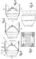
- Fig. 1
- eine Seitenansicht des Luftaustritts im Querschnitt mit Strömungsteiler,
- Fig. 2
- eine Stirnansicht des Luftaustritts gemäß Fig. 1,
- Fig. 3
- eine Seitenansicht des Luftaustritts mit lamellenförmigen Strömungsleitelementen,
- Fig.
- eine Seitenansicht des Luftaustritts mit einer Drosselvorrichtung in Form von Lochplatten,
- Fig. 5
- eine Seitenansicht einer anderen Form eines Luftaustritts im Querschnitt mit gleichförmig verstellbaren, lamellenförmigen Strömungsleitelementen,
- Fig. 6
- eine Seitenansicht des Luftaustritts gemäß Fig. 5 mit gegenläufig verstellbaren, lamellenförmigen Strömungsleitelementen,
- Fig. 7
- einen Luftaustritt mit zwei Austrittsfeldern und Strömungsteiler,
- Fig. 8
- eine Frontansicht eines Luftaustritts gemäß Fig. 4, 5, 6 und 7,
- Fig. 9
- eine Aufsicht auf den Luftaustritt gemäß Fig. 4, 5, 6 und 7,
- Fig. 10
- eine Abwandlung der Ausführungsform gem. Fig. 5 mit Vorkanal für die Treibdüse,
- Fig. 11
- eine Abwandlung der Ausführungsform gem. Fig. 10.
- Fig. 12
- eine Ausführungsform gem. Fig. 10 mit Seitenauslaß.
Claims (13)
- Luftaustritt für Belüftungsanlagen zur Belüftung von Räumen, insbesondere hallenartigen Räumen, der am Austritt eines Luftzufuhrkanals angeordnet ist und wenigstens eine Treibdüse für einen Treibstrahl und wenigstens ein der Treibdüse benachbartes Austrittsfeld für Schleppluft aufweist, wobei Treibdüse und Austrittsfeld mit Zuluft aus dem Luftzufuhrkanal beaufschlagt werden, dadurch gekennzeichnet, daß am Austritt Mittel (6) zur Beeinflussung der Luftströmung im Luftzufuhrkanal (2) angeordnet sind, mit denen der Luftdurchsatz durch die Treibdüse (3) und durch das Austrittsfeld (4) im Verhältnis zueinander aufgeteilt wird.
- Luftaustritt nach Anspruch 1, dadurch gekennzeichnet, daß das Mittel (6) zur Beeinflussung der Luftströmung einstellbar ausgebildet ist.
- Luftaustritt nach Anspruch 1 oder 2, dadurch gekennzeichnet, daß das Mittel (6) zur Beeinflussung der Luftströmung wenigstens einen Strömungsteiler (6.1) aufweist, durch den die Luftmenge auf die Treibdüse (3) und das Austrittsfeld (4) aufgeteilt wird.
- Luftaustritt nach einem der Ansprüche 1 bis 3, dadurch gekennzeichnet, daß das Mittel (6) zur Beeinflussung der Luftströmung durch wenigstens eine wenigstens dem Austrittsfeld (4) angeordnete Drosselvorrichtung (6.2) gebildet wird.
- Luftaustritt gemäß einem der Ansprüche 1 bis 4, dadurch gekennzeichnet, daß die Drosselvorrichtung (6.2) wenigstens zwei quer zur Richtung der Luftströmung und vorzugsweise mit Abstand hintereinander angeordnete Lochplatten (6.3) aufweist.
- Luftaustritt nach einem der Ansprüche 1 bis 5, dadurch gekennzeichnet, daß die Lochplatten (6.3) zur Veränderung des Durchtrittswiderstandes in der Plattenebene gegeneinander verschiebbar sind, wobei der geringste Durchtrittswiderstand bei einer Stellung der Platten erreichbar ist, wenn die Löcher in Strömungsrichtung hintereinander liegen.
- Luftaustritt nach einem der Ansprüche 1 bis 6, dadurch gekennzeichnet, daß das Mittel (6) zur Beeinflussung der Luftströmung mehrere relativ zueinander verschwenkbare, lamellenförmige Strömungsleitelemente (8) zur Leitung und/oder Hemmung des Luftstroms aufweist.
- Luftaustritt nach einem der Ansprüche 1 bis 7, dadurch gekennzeichnet, daß das Mittel (6) zur Beeinflussung der Luftströmung als Kassette (12) in den Luftzufuhrkanal (2) einschiebbar und herausziehbar ausgebildet ist.
- Luftaustritt nach einem der Ansprüche 1 bis 8, dadurch gekennzeichnet, daß die Strömungsleitelemente (8) in einer Bezugsebene (10) nebeneinander angeordnet sind und daß diese Bezugsebenen gegenüber der Ebene des Austrittsfeldes (4) geneigt angeordnet ist.
- Luftaustritt nach einem der Ansprüche 1 bis 9, dadurch gekennzeichnet, daß das Austrittsfeld (4) gegen die Achse des Treibstrahls geneigt ausgerichtet ist und zugleich eine Abschirmung (5) gegenüber der Raumluft bildet.
- Luftaustritt nach einem der Ansprüche 1 bis 10, dadurch gekennzeichnet, daß der Treibdüse (3) ein in den Luftzufuhrkanal (2) gegen die Strömungsrichtung der Luft ragender Vorkanal (11) zugeordnet ist.
- Luftaustritt nach einem der Ansprüche 1 bis 11, dadurch gekennzeichnet, daß der Vorkanal (11) an seinem Eintritt mit relativ zueinander verschwenkbaren lamellenförmigen Strömungsleitelementen (8) zur Veränderung des Luftdurchsatzes versehen ist.
- Luftaustritt nach einem der Ansprüche 1 bis 12, mit wenigstens einem gegen die Achse (7) des Treibstrahls geneigt ausgerichteten Austrittsfeld (4), dadurch gekennzeichnet, daß auf der dem Austrittsfeld (4) abgewandten Seite wenigstens ein Seitenauslaß (13) angeordnet ist.
Applications Claiming Priority (2)
| Application Number | Priority Date | Filing Date | Title |
|---|---|---|---|
| DE29722570U DE29722570U1 (de) | 1997-12-20 | 1997-12-20 | Luftaustritt für Belüftungsanlagen |
| DE29722570U | 1997-12-20 |
Publications (3)
| Publication Number | Publication Date |
|---|---|
| EP0924474A2 true EP0924474A2 (de) | 1999-06-23 |
| EP0924474A3 EP0924474A3 (de) | 2000-11-08 |
| EP0924474B1 EP0924474B1 (de) | 2005-05-11 |
Family
ID=8050289
Family Applications (1)
| Application Number | Title | Priority Date | Filing Date |
|---|---|---|---|
| EP98123339A Expired - Lifetime EP0924474B1 (de) | 1997-12-20 | 1998-12-08 | Luftaustritt für Belüftungsanlagen |
Country Status (2)
| Country | Link |
|---|---|
| EP (1) | EP0924474B1 (de) |
| DE (2) | DE29722570U1 (de) |
Cited By (3)
| Publication number | Priority date | Publication date | Assignee | Title |
|---|---|---|---|---|
| WO2005072038A1 (en) * | 2004-01-27 | 2005-08-04 | Rc Group Spa | Displacement conditioner with air jet air distribution |
| EP2199700A1 (de) * | 2008-12-10 | 2010-06-23 | RC-Linja Oy | Zuluftvorrichtung |
| JP2021523338A (ja) * | 2018-05-30 | 2021-09-02 | クランツ ゲー・エム・ベー・ハーKrantz GmbH | 置換空気流出部 |
Citations (1)
| Publication number | Priority date | Publication date | Assignee | Title |
|---|---|---|---|---|
| WO1995001537A1 (de) | 1993-06-30 | 1995-01-12 | Adam Bernhardt | Luftaustritt für belüftungsanlangen |
Family Cites Families (2)
| Publication number | Priority date | Publication date | Assignee | Title |
|---|---|---|---|---|
| US3946647A (en) * | 1973-05-07 | 1976-03-30 | Aktiebolaget Svenska Flaktfabriken | Device for preferably cooling a room by a ventilation air stream |
| DE2851046A1 (de) * | 1978-11-25 | 1980-06-04 | Walter Ing Grad Hirsch | Luftauslassvorrichtung fuer raumklimatisierungs- und belueftungsanlagen |
-
1997
- 1997-12-20 DE DE29722570U patent/DE29722570U1/de not_active Expired - Lifetime
-
1998
- 1998-12-08 DE DE59812785T patent/DE59812785D1/de not_active Expired - Fee Related
- 1998-12-08 EP EP98123339A patent/EP0924474B1/de not_active Expired - Lifetime
Patent Citations (1)
| Publication number | Priority date | Publication date | Assignee | Title |
|---|---|---|---|---|
| WO1995001537A1 (de) | 1993-06-30 | 1995-01-12 | Adam Bernhardt | Luftaustritt für belüftungsanlangen |
Cited By (3)
| Publication number | Priority date | Publication date | Assignee | Title |
|---|---|---|---|---|
| WO2005072038A1 (en) * | 2004-01-27 | 2005-08-04 | Rc Group Spa | Displacement conditioner with air jet air distribution |
| EP2199700A1 (de) * | 2008-12-10 | 2010-06-23 | RC-Linja Oy | Zuluftvorrichtung |
| JP2021523338A (ja) * | 2018-05-30 | 2021-09-02 | クランツ ゲー・エム・ベー・ハーKrantz GmbH | 置換空気流出部 |
Also Published As
| Publication number | Publication date |
|---|---|
| DE29722570U1 (de) | 1999-06-10 |
| DE59812785D1 (de) | 2005-06-16 |
| EP0924474B1 (de) | 2005-05-11 |
| EP0924474A3 (de) | 2000-11-08 |
Similar Documents
| Publication | Publication Date | Title |
|---|---|---|
| EP3620585B1 (de) | Sanitäres einbauteil | |
| DE3871861T2 (de) | Doppelduese kabinenbelueftungssystem. | |
| DE60102036T2 (de) | Luftauslass an der Decke einer Flugzeugkabine | |
| DE3740714A1 (de) | Luftstromverteiler | |
| EP1986912A2 (de) | Aerodynamische klappe eines flugzeugs mit einer den klappenwirbel beeinflussenden vorrichtung | |
| DE102008050546A1 (de) | Side-Feeder-Luftführungselement für eine Flugzeugklimaanlage | |
| DE2609030C3 (de) | Vorrichtung zum Führen von aus einer luftdurchlässigen perforierten Fläche austretenden Luftströmen | |
| EP3321113B1 (de) | Luftausströmer | |
| DE2556538A1 (de) | Verfahren und vorrichtung zur ventilierung bzw. temperierung von raeumen | |
| EP3327366B1 (de) | Luftauslass zum temperieren eines raumes | |
| DE3823448A1 (de) | Vorrichtung zum beheizen des fahrgastraumes eines kraftfahrzeuges | |
| DE2320134C3 (de) | Verfahren und Vorrichtung zum Belüften von Räumen | |
| EP1243450A2 (de) | Strömungsauslassvorrichtung, insbesondere für ein Fahrzeuginnenraum-Belüftungssystem | |
| EP0988165A1 (de) | Luftstromregulierungsdüse zur belüftung eines kraftfahrzeuginnenraumes | |
| DE2242582C3 (de) | LuftauslaB-Vorrichtung für Raumklimatisierungs- und Belüftungsanlagen | |
| DE1154252B (de) | Abschirmung von Raumoeffnungen durch einen Luftschleier | |
| DE2851046A1 (de) | Luftauslassvorrichtung fuer raumklimatisierungs- und belueftungsanlagen | |
| DE68912125T2 (de) | Geradliniges wassersprühgerät zur kühlung von blechen. | |
| DE2138539C3 (de) | Luftauslaßeinrichtung | |
| EP0924474B1 (de) | Luftaustritt für Belüftungsanlagen | |
| EP0657014B1 (de) | Luftaustritt für belüftungsanlangen | |
| EP0816772B1 (de) | Luftauslass | |
| DE102022100478A1 (de) | Luftausströmer für ein fahrzeug sowie luftausströmersystem | |
| DE2207514C2 (de) | Langgestreckte Luftaustrittsvorrichtung mit verstellbaren Ausblasöffnungen | |
| DE102021117250A1 (de) | Luftausströmer für ein fahrzeug |
Legal Events
| Date | Code | Title | Description |
|---|---|---|---|
| PUAI | Public reference made under article 153(3) epc to a published international application that has entered the european phase |
Free format text: ORIGINAL CODE: 0009012 |
|
| AK | Designated contracting states |
Kind code of ref document: A2 Designated state(s): BE DE DK FR GB NL |
|
| AX | Request for extension of the european patent |
Free format text: AL;LT;LV;MK;RO;SI |
|
| PUAL | Search report despatched |
Free format text: ORIGINAL CODE: 0009013 |
|
| AK | Designated contracting states |
Kind code of ref document: A3 Designated state(s): AT BE CH CY DE DK ES FI FR GB GR IE IT LI LU MC NL PT SE |
|
| AX | Request for extension of the european patent |
Free format text: AL;LT;LV;MK;RO;SI |
|
| RIC1 | Information provided on ipc code assigned before grant |
Free format text: 7F 24F 13/06 A, 7F 24F 13/26 B |
|
| 17P | Request for examination filed |
Effective date: 20010417 |
|
| AKX | Designation fees paid |
Free format text: BE DE DK FR GB NL |
|
| 17Q | First examination report despatched |
Effective date: 20030812 |
|
| GRAP | Despatch of communication of intention to grant a patent |
Free format text: ORIGINAL CODE: EPIDOSNIGR1 |
|
| GRAS | Grant fee paid |
Free format text: ORIGINAL CODE: EPIDOSNIGR3 |
|
| GRAA | (expected) grant |
Free format text: ORIGINAL CODE: 0009210 |
|
| AK | Designated contracting states |
Kind code of ref document: B1 Designated state(s): BE DE DK FR GB NL |
|
| REG | Reference to a national code |
Ref country code: GB Ref legal event code: FG4D Free format text: NOT ENGLISH |
|
| REF | Corresponds to: |
Ref document number: 59812785 Country of ref document: DE Date of ref document: 20050616 Kind code of ref document: P |
|
| PG25 | Lapsed in a contracting state [announced via postgrant information from national office to epo] |
Ref country code: DK Free format text: LAPSE BECAUSE OF FAILURE TO SUBMIT A TRANSLATION OF THE DESCRIPTION OR TO PAY THE FEE WITHIN THE PRESCRIBED TIME-LIMIT Effective date: 20050811 |
|
| GBT | Gb: translation of ep patent filed (gb section 77(6)(a)/1977) |
Effective date: 20050907 |
|
| PG25 | Lapsed in a contracting state [announced via postgrant information from national office to epo] |
Ref country code: GB Free format text: LAPSE BECAUSE OF NON-PAYMENT OF DUE FEES Effective date: 20051208 |
|
| PG25 | Lapsed in a contracting state [announced via postgrant information from national office to epo] |
Ref country code: BE Free format text: LAPSE BECAUSE OF NON-PAYMENT OF DUE FEES Effective date: 20051231 |
|
| PLBE | No opposition filed within time limit |
Free format text: ORIGINAL CODE: 0009261 |
|
| STAA | Information on the status of an ep patent application or granted ep patent |
Free format text: STATUS: NO OPPOSITION FILED WITHIN TIME LIMIT |
|
| ET | Fr: translation filed | ||
| 26N | No opposition filed |
Effective date: 20060214 |
|
| PG25 | Lapsed in a contracting state [announced via postgrant information from national office to epo] |
Ref country code: NL Free format text: LAPSE BECAUSE OF NON-PAYMENT OF DUE FEES Effective date: 20060701 Ref country code: DE Free format text: LAPSE BECAUSE OF NON-PAYMENT OF DUE FEES Effective date: 20060701 |
|
| GBPC | Gb: european patent ceased through non-payment of renewal fee |
Effective date: 20051208 |
|
| NLV4 | Nl: lapsed or anulled due to non-payment of the annual fee |
Effective date: 20060701 |
|
| BERE | Be: lapsed |
Owner name: *BERNHARDT ADAM Effective date: 20051231 |
|
| PG25 | Lapsed in a contracting state [announced via postgrant information from national office to epo] |
Ref country code: FR Free format text: LAPSE BECAUSE OF NON-PAYMENT OF DUE FEES Effective date: 20051231 |
|
| REG | Reference to a national code |
Ref country code: FR Ref legal event code: ST Effective date: 20111209 |