EP0924475A1 - Clapet pour régler le débit d'air - Google Patents
Clapet pour régler le débit d'air Download PDFInfo
- Publication number
- EP0924475A1 EP0924475A1 EP97122079A EP97122079A EP0924475A1 EP 0924475 A1 EP0924475 A1 EP 0924475A1 EP 97122079 A EP97122079 A EP 97122079A EP 97122079 A EP97122079 A EP 97122079A EP 0924475 A1 EP0924475 A1 EP 0924475A1
- Authority
- EP
- European Patent Office
- Prior art keywords
- vane
- airflow
- closing
- adjusting damper
- plates
- Prior art date
- Legal status (The legal status is an assumption and is not a legal conclusion. Google has not performed a legal analysis and makes no representation as to the accuracy of the status listed.)
- Withdrawn
Links
Images











Classifications
-
- F—MECHANICAL ENGINEERING; LIGHTING; HEATING; WEAPONS; BLASTING
- F24—HEATING; RANGES; VENTILATING
- F24F—AIR-CONDITIONING; AIR-HUMIDIFICATION; VENTILATION; USE OF AIR CURRENTS FOR SCREENING
- F24F13/00—Details common to, or for air-conditioning, air-humidification, ventilation or use of air currents for screening
- F24F13/08—Air-flow control members, e.g. louvres, grilles, flaps or guide plates
- F24F13/10—Air-flow control members, e.g. louvres, grilles, flaps or guide plates movable, e.g. dampers
- F24F13/14—Air-flow control members, e.g. louvres, grilles, flaps or guide plates movable, e.g. dampers built up of tilting members, e.g. louvre
- F24F13/1426—Air-flow control members, e.g. louvres, grilles, flaps or guide plates movable, e.g. dampers built up of tilting members, e.g. louvre characterised by actuating means
-
- F—MECHANICAL ENGINEERING; LIGHTING; HEATING; WEAPONS; BLASTING
- F24—HEATING; RANGES; VENTILATING
- F24F—AIR-CONDITIONING; AIR-HUMIDIFICATION; VENTILATION; USE OF AIR CURRENTS FOR SCREENING
- F24F13/00—Details common to, or for air-conditioning, air-humidification, ventilation or use of air currents for screening
- F24F13/08—Air-flow control members, e.g. louvres, grilles, flaps or guide plates
- F24F13/10—Air-flow control members, e.g. louvres, grilles, flaps or guide plates movable, e.g. dampers
- F24F13/14—Air-flow control members, e.g. louvres, grilles, flaps or guide plates movable, e.g. dampers built up of tilting members, e.g. louvre
- F24F13/1413—Air-flow control members, e.g. louvres, grilles, flaps or guide plates movable, e.g. dampers built up of tilting members, e.g. louvre using more than one tilting member, e.g. with several pivoting blades
-
- F—MECHANICAL ENGINEERING; LIGHTING; HEATING; WEAPONS; BLASTING
- F24—HEATING; RANGES; VENTILATING
- F24F—AIR-CONDITIONING; AIR-HUMIDIFICATION; VENTILATION; USE OF AIR CURRENTS FOR SCREENING
- F24F13/00—Details common to, or for air-conditioning, air-humidification, ventilation or use of air currents for screening
- F24F13/08—Air-flow control members, e.g. louvres, grilles, flaps or guide plates
- F24F13/10—Air-flow control members, e.g. louvres, grilles, flaps or guide plates movable, e.g. dampers
- F24F13/14—Air-flow control members, e.g. louvres, grilles, flaps or guide plates movable, e.g. dampers built up of tilting members, e.g. louvre
- F24F13/1486—Air-flow control members, e.g. louvres, grilles, flaps or guide plates movable, e.g. dampers built up of tilting members, e.g. louvre characterised by bearings, pivots or hinges
-
- F—MECHANICAL ENGINEERING; LIGHTING; HEATING; WEAPONS; BLASTING
- F24—HEATING; RANGES; VENTILATING
- F24F—AIR-CONDITIONING; AIR-HUMIDIFICATION; VENTILATION; USE OF AIR CURRENTS FOR SCREENING
- F24F13/00—Details common to, or for air-conditioning, air-humidification, ventilation or use of air currents for screening
- F24F13/24—Means for preventing or suppressing noise
-
- F—MECHANICAL ENGINEERING; LIGHTING; HEATING; WEAPONS; BLASTING
- F24—HEATING; RANGES; VENTILATING
- F24F—AIR-CONDITIONING; AIR-HUMIDIFICATION; VENTILATION; USE OF AIR CURRENTS FOR SCREENING
- F24F13/00—Details common to, or for air-conditioning, air-humidification, ventilation or use of air currents for screening
- F24F13/08—Air-flow control members, e.g. louvres, grilles, flaps or guide plates
- F24F13/10—Air-flow control members, e.g. louvres, grilles, flaps or guide plates movable, e.g. dampers
- F24F13/14—Air-flow control members, e.g. louvres, grilles, flaps or guide plates movable, e.g. dampers built up of tilting members, e.g. louvre
- F24F13/1426—Air-flow control members, e.g. louvres, grilles, flaps or guide plates movable, e.g. dampers built up of tilting members, e.g. louvre characterised by actuating means
- F24F2013/1433—Air-flow control members, e.g. louvres, grilles, flaps or guide plates movable, e.g. dampers built up of tilting members, e.g. louvre characterised by actuating means with electric motors
-
- F—MECHANICAL ENGINEERING; LIGHTING; HEATING; WEAPONS; BLASTING
- F24—HEATING; RANGES; VENTILATING
- F24F—AIR-CONDITIONING; AIR-HUMIDIFICATION; VENTILATION; USE OF AIR CURRENTS FOR SCREENING
- F24F13/00—Details common to, or for air-conditioning, air-humidification, ventilation or use of air currents for screening
- F24F13/08—Air-flow control members, e.g. louvres, grilles, flaps or guide plates
- F24F13/10—Air-flow control members, e.g. louvres, grilles, flaps or guide plates movable, e.g. dampers
- F24F13/14—Air-flow control members, e.g. louvres, grilles, flaps or guide plates movable, e.g. dampers built up of tilting members, e.g. louvre
- F24F13/1426—Air-flow control members, e.g. louvres, grilles, flaps or guide plates movable, e.g. dampers built up of tilting members, e.g. louvre characterised by actuating means
- F24F2013/1446—Air-flow control members, e.g. louvres, grilles, flaps or guide plates movable, e.g. dampers built up of tilting members, e.g. louvre characterised by actuating means with gearings
-
- F—MECHANICAL ENGINEERING; LIGHTING; HEATING; WEAPONS; BLASTING
- F24—HEATING; RANGES; VENTILATING
- F24F—AIR-CONDITIONING; AIR-HUMIDIFICATION; VENTILATION; USE OF AIR CURRENTS FOR SCREENING
- F24F13/00—Details common to, or for air-conditioning, air-humidification, ventilation or use of air currents for screening
- F24F13/08—Air-flow control members, e.g. louvres, grilles, flaps or guide plates
- F24F13/10—Air-flow control members, e.g. louvres, grilles, flaps or guide plates movable, e.g. dampers
- F24F13/14—Air-flow control members, e.g. louvres, grilles, flaps or guide plates movable, e.g. dampers built up of tilting members, e.g. louvre
- F24F13/1426—Air-flow control members, e.g. louvres, grilles, flaps or guide plates movable, e.g. dampers built up of tilting members, e.g. louvre characterised by actuating means
- F24F2013/1473—Air-flow control members, e.g. louvres, grilles, flaps or guide plates movable, e.g. dampers built up of tilting members, e.g. louvre characterised by actuating means with cams or levers
Definitions
- This invention relates to an air conditioner damper which is provided in the back of a ceiling of a building and disposed in the middle of a duct, or more particularly to an airflow-adjusting damper.
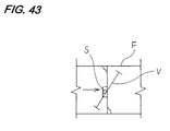
- FIG. 43 shows a schematic sectional view of a conventional airflow-adjusting damper.
- the damper shown here comprises a box-like frame F having a predetermined thickness, a rotation shaft S which is supported by bearing provided in the frame F and a butterfly vane V which is rotated so as to open/close the airflow path in the frame F, an end of the rotation shaft S being extended and connected to a handle or an output shaft of a motor.
- the present invention has been achieved to solve the aforementioned problems, and it therefore is an object of the invention to provide an airflow-adjusting damper which is structured in a very simple way and capable of preventing occurrence of a large wind noise produced when the vanes are opened/closed, preventing drift current from being generated in the vicinity of edges of the vanes of the damper, performing rectification of the air flow and largely improving airflow detection accuracy of a sensor.
- a first aspect of the present invention provides airflow-adjusting dampers 10-1, 10-2, 10-3, 10-4, 10-5 comprising each: a casing 12 in which an airflow path P is formed internally; and vane portions 14, 62, 64 which are rotated in the casing so as to open/close the airflow path, the vane portions 14, 62, 64 containing a plurality of vane plates 16a, 16b, 66a, 66b, 68a, 68b which are overlaid mutually, slidably mounted thereon and have a plurality of holes 18.
- the vane plates are rotated in the airflow path with the rotation of the rotation shafts, for example, they incline gradually from their full opening state, so that airflow resistance is increased gradually thereby restricting the airflow.
- the vane portions are rotated in this airflow path, the vane plates of the vane portions are opened/closed with the plural holes communicating with each other so as to form the communicating openings.
- airflow is always allowed to pass through the holes ensuring a small amount of airflow. Because airflow is divided by the plural communicating opening and flows in the downstream, no large wind noise is produced.
- this damper can be said to be very low noise type damper.
- the rotation of the rotation shaft may be carried out by manual operation by extending a part of the rotation shaft or carried out by a driving means such as a motor.
- the plural holes are made to communicate with each other, and then air is made to flow through these plural holes in fine division fashion.
- wind noise and other noise can be prevented from occurring.
- this apparatus can be installed in the vicinity of an air conditioner and the application of this type of the air conditioning damper can be expanded largely. Further, because no drift current is produced, the detecting accuracy of the air speed sensor installed in the upstream is increased largely.
- the senor detects the entire cross section, it is not necessary to provide a plurality thereof. With only a single sensor, it is possible to detect wind speed at a high accuracy. Thus, sensor cost and installation cost thereof can be saved thereby contributing to reduction of the total cost. Further, when the vane portions are almost fully closed, it is possible to detect a fine airflow rate.
- a second aspect of the invention provides an airflow-adjusting damper according to the first aspect wherein, when an entire airflow path P is opened/closed by the vane portions 14, 62, 64, the plural holes 18 are made to communicate with each other to form communicating openings and after the airflow path P is closed, any of said vane plates 16a, 16b, 66a, 66b, 68a, 68b is slid so as to close said communicating openings.
- the vane plates containing the plural holes open/close the airflow path in the casing.
- minimum amount of air is made to flow equally over the entire cross section of the airflow path in all interval from the full opening state to the full closing state, thereby preventing drift current and assuring rectification of current.
- no wind noise is produced when the vane plates are near the full closing state.
- an ideal damper can be expected.
- by fully closing the flow path and then fully closing the plural holes fine adjustment of the airflow can be performed.
- a third aspect of the invention provides an airflow-adjusting damper according to the second aspect wherein rotation shafts 22, 58, 60 are rotatably provided so as to cross over the casing 12, the vane portions 14, 62, 64 being mounted on the rotation shafts 22, 58, 60, the airflow-adjusting damper further comprising a shared drive mechanism 28 which carries out opening/closing of the airflow path and opening/closing of the plural holes 18 by rotating the rotation shafts 22, 58, 60.
- opening/closing of the flow path in the casing and opening/closing of the plural holes formed in the vane plates can be carried out by a single driving system.
- common components can be used for both the operations and the structure can be simplified.
- the driving system can be formed in a small size thereby realizing light weight. Thus, this system is easy to handle.
- a fourth aspect of the invention provides an airflow-adjusting damper according to the third aspect wherein the shared drive mechanism 28 is so constructed as to slide the vane portions so as to close the plural holes 18 by further rotating the rotation shafts 22, 58, 60 continuously from the condition in which the airflow path is closed.
- a series motion from the full opening state of the airflow path to the full closing state by rotating the vane portions by the rotation of the rotation shafts is a primary rotation
- a secondary rotation that is, further rotation of the rotation shaft from the full closing state
- the rotation shafts are rotated from the condition in which the vane plates are opened to the condition in which the vane plates are closed, and by rotating further the rotation shafts, the vane plates can be slid so as to fully close the communicating openings which are provided by a plurality of the holes in simple structure, without any electrical control, link or other interlocking mechanism. Further by continuing the rotation of the rotation shafts, slide conversion can be carried out. Thus, the produced motions are continuous thereby producing no waste in motion.
- the airflow control characteristic with nearly fully opening condition is improved.
- a fifth aspect of the invention provides an airflow-adjusting damper according to the third aspect wherein the shared drive mechanism 28 comprises the rotation shafts 22, 58, 60 which are rotatably provided on the casing and the vane portions 14, 62, 64 mounted on the rotation shafts 22, 58, 60, the vane portions 14, 62, 64 including first vane plates 16a, 50a, 66a, 68a which are mounted idlingly on the rotation shafts 22, 58, 60 and other vane plates 16b, 50b, 66b, 68b which are slidably fixed to the first vane plates, the airflow-adjusting damper further comprising long grooves 40, 42, 52, 54, 84, 86 formed in each of the vane plates 16a, 50a, 66a, 16b, 50b, 66b, 68b, driving pins 38 which are fixed on the rotation shafts 22, 58, 60 in the radius direction and go thorough the long grooves 40, 42, 52, 54, 84, 86 in the overlaid plural vane plates
- the driving pin is rotated so that the driving pin moves in the long groove thereby realizing the shared drive operation.
- the components necessary for achieving this device are basically, only the driving pins provided on the rotation shafts and the long grooves formed in the vane plates.
- it is not necessary to provide a driving mechanism opening/closing the plural holes formed in the vane portions separately from the driving power for opening/closing the flow path and the structure is very simple. Because mechanical conversion is carried out without any electrical control by assuring easiness of production and easiness of maintenance and inspection, thereby improving production efficiency, fault ratio in the machine itself is very low.
- a sixth aspect of the invention provides an airflow-adjusting damper according to the fifth aspect wherein the long grooves 84, 86 are set to such a length including a rotation range of the driving pin 38 which, when the rotation shafts 58, 60 are further rotated from the condition in which the airflow path is closed by the van portions 62, 64, hooks other vane plates 66b, 68b so as to slide them until the plural holes 18 are completely closed.
- the vane plate of the sliding side is slid.
- the other vane plate of the sliding side only has to be overlaid. Consequently, the opening/closing of the entire flow path by the vane portion and opening/closing of the plural holes by sliding of the overlaid vane plates can be achieved.
- a seventh aspect of the invention provides an airflow-adjusting damper according to the third aspect wherein the shared drive mechanism 28 contains urging members 46 for always applying an urging force in such a direction that the plural holes 18 in the plural vane plates 66a, 66b, 68a, 68b form communicating openings.
- the urging mechanism is simple. Because the coil spring is used so that an end thereof is hooked on the vane plate not to be slid, a simple structure is attained.
- a single coil spring can be used for this purpose.
- a structure therefor is very simple and when the plural holes are closed after the flow path is closed, no special structure for achieving this series operation is needed, so that the shared drive mechanism can be simplified in structure and made effective.
- no special structure for achieving this series operation is needed, so that the shared drive mechanism can be simplified in structure and made effective.
- An eighth aspect of the invention provides an airflow-adjusting damper according to the fifth aspect wherein the long grooves 40, 42, 52, 54 are provided in each of the vane plates 16a, 16b, 50a, 50b so as to form a through portion for the driving pin 38 and formed so that they direct at least in different directions.
- the long groove in the first vane plate which is the vane plate, which is not to be slid acts as a guide groove.
- the driving pin is rotated in this groove at right angle, the other vane plate having a long groove which is formed in a different direction is slid along the long groove.
- the rotary motion can be converted directly to a linear motion.
- the driving pin installed on the rotation shaft is rotated by the rotation of the rotation shaft while it is kept through the long groove formed in the vane plate, by forming the long grooves so as to direct in different directions, the vane plate is slid in the length direction of the rotation shaft by a deviated amount in the width direction of the long groove.
- the conversion mechanism can be formed in very simple structure and is easy to maintain and inspect, and unlikely to be in fault.
- a ninth aspect of the invention provides an airflow-adjusting damper according to the fifth aspect wherein the other vane plates 16b are provided slidably along the rotation shafts 22.
- the vane plate not to be slid contains the long groove in a direction perpendicular to the rotation shaft and the vane plate to be slid contains the long groove of the direction at angle of the V-letter shape. Consequently, the vane plate of the movable side is slid in the direction along the rotation shaft.
- the structure of the vane plate side to be slid can be made concrete and realized. Because it is along the rotation shaft, there is no waste in the supporting/guiding structure and production thereof is easy.
- a tenth aspect of the invention provides an airflow-adjusting damper according to the fifth aspect wherein the other vane plates 66b, 68b are provided in a direction intersecting the rotation shafts 58, 60.
- the opening/closing of the plural holes can be carried out also by a motion in the direction intersecting the rotation shaft. Particularly when plural vane portions are formed on plural rotation shafts, this can be achieved effectively.
- the structure of the vane plate side to be slid can be made concrete and realized.
- An eleventh aspect of the invention provides an airflow-adjusting damper according to the fifth aspect wherein the plural vane plates 16a, 50a, 66a, 68a, 16b, 50b, 66b, 68b are provided so that they are slidingly rotatable.
- sliding rotation also can achieve opening/closing of the plural holes formed in the vane plates. Because this is not linear motion but rotary motion, the vane plate to be slid and the vane not to be slid may be formed in the same size, so that production process can be simplified and the openings can be provided near the edge of the vane plates.
- the structure of the vane plate side to be slid can be made concrete and realized.
- a twelfth aspect of the invention provides an airflow-adjusting damper according to the eleventh aspect wherein the plural vane plates 50a, 50b are formed in circular shape, the long groove 52 in the first vane plate 50a is formed longer in a direction intersecting the rotation shaft 22 and the long groove 54 in the other vane plate 50b which is slidingly rotatable relative to the vane plate 50a is formed longer in the radius direction of the vane plate 50b than the pin diameter of the driving pin 38.
- a thirteenth aspect of the invention provides an airflow-adjusting damper according to the fifth aspect wherein the rotation shafts 22, 58, 60 and vane portion 14, 62, 64 contains flow path opening/closing urging member 88 for urging the vane portions in the direction of closing the flow path or opening the flow path.
- the opening/closing motion of the vane portion in the airflow path is stabilized.
- a fourteenth aspect of the invention provides an airflow-adjusting damper according to the thirteenth aspect wherein the flow path opening/closing urging member 88 comprises a urging spring, which is stretched over the other vane plates 66b, 68b, acting as a pressing against the first vane plate 66a, 68a.
- the opening/closing motion of the vane portion in the airflow path is stabilized and at the same time, slip-off of the vane plate to be slid is prevented and holding of the hole open position is assured.
- a fifteenth aspect of the invention provides an airflow-adjusting damper according to the third aspect wherein the rotation shafts 58, 60 are provided in plurality so as to cross over the casing 12 and the vane portions 62, 64 for opening/closing the flow path P while engaged therewith are provided in plurality.
- a single flow path can be opened or closed with the plural vane plates, and particularly it is possible to achieve restriction of drift current and improvement of airflow control characteristic.
- a sixteenth aspect of the invention provides an airflow-adjusting damper according to the fifteenth aspect wherein the rotation shafts 58, 60 on which the vane portions 62, 64 are engaged are disposed in series relative to the airflow path, the vane portions 62, 64 being provided so as to rotate in opposite directions to close the flow path.
- the plural vane portions are provided in the flow path thereby reducing loss of resistance. Further, by rotating the vane plates in opposite directions, the flow path is opened/closed in butterfly fashion, thereby equalizing airflow pass, preventing drift current and assuring rectification of current.
- a seventeenth aspect of the invention provides an airflow-adjusting damper according to the fifteenth aspect further comprising a synchronous opening/closing mechanism 90 for synchronously opening/closing the plural vane portions 62, 64.
- the plural vane portions can be opened/closed synchronously, and particularly improvement of the airflow control characteristic when the plural vane portions are opened/closed in butterfly fashion can be assured.
- An eighteenth aspect of the invention provides an airflow-adjusting damper according to the fifteenth aspect wherein two of the rotation shafts 58, 60 are provided in the flow path and the vane portions 62, 64 are fixed thereto such that two pairs of the vane portions open/close two-division planes of the airflow path P.
- a pair of the two-divided vane portions is charged of each of the divided flow path. Consequently, the semi-circular vane portions can be formed and by supporting ends thereof by the rotation shafts, the opening/closing mechanism in butterfly fashion can be realized.
- a nineteenth aspect of the invention provides an airflow-adjusting damper according to the third aspect wherein the shared drive mechanism 28 comprises the rotation shafts 22 which are rotatably provided in the casing 12 and the vane portions 14 which are mounted on the rotation shafts 22, the vane portions 14 including the first vane plate 16a which is mounted idlingly relative to the rotation shafts 22 and other vane plate 16b which is fixed slidably to the first vane plate 16a, the rotation shaft 22 containing a screw portion 126, the airflow-adjusting damper further comprising a retracting mechanism 128 which is engaged with the screw portion 126 so as to slide any of the vane plates 16b, ⁇ .
- the shared drive mechanism 28 comprises the rotation shafts 22 which are rotatably provided in the casing 12 and the vane portions 14 which are mounted on the rotation shafts 22, the vane portions 14 including the first vane plate 16a which is mounted idlingly relative to the rotation shafts 22 and other vane plate 16b which is fixed slidably to the first vane plate 16a
- the screw portion is formed on the rotation shaft and this screw portion is made to interconnect with the vane plate so that the rotation of the screw portion slides the vane plate.
- the shared drive is carried out by engaging structure between the screw portion and retracting mechanism, so that shift between opening/closing of the flow path and opening/closing of the plural holes can be performed smoothly and securely.
- the operation thereof is performed securely.
- a 20th aspect of the invention provides an airflow-adjusting damper according to the nineteenth aspect wherein the retracting mechanism 128 comprises a nut member 134 which engages the screw portion 126 while fixed to the other vane plate 16b so that it advances or retracts along the rotation shaft 22, and an urging member (138) for always urging the first vane plate 16a in the direction of closing the flow path.
- the retracting mechanism 128 comprises a nut member 134 which engages the screw portion 126 while fixed to the other vane plate 16b so that it advances or retracts along the rotation shaft 22, and an urging member (138) for always urging the first vane plate 16a in the direction of closing the flow path.
- the retracting mechanism performs engagement between the nut member fixed to the vane plate of the sliding side and the screw portion.
- the shared drive structure by engagement with the screw portion can be achieved and thus the operation is performed securely.
- a 21st aspect of the invention provides an airflow-adjusting damper according to the third aspect wherein said shared drive mechanism comprises the plural vane plates and double shaft structure containing a middle shaft and an outer shaft.
- the shared drive mechanism has simplified a structure for transmitting power to two systems in carrying out the opening/closing of the airflow path by the vane plates and opening/closing of the plural holes by sliding of the vane plates. Consequently, the shift mechanism for these two motions by continuous rotation of the rotation shaft can be achieved relatively easily.
- the opening/closing of the plural holes by the rotation of the rotation shafts outside/inside the casing and sliding motion of the vane plates can be performed easily without necessity of complicated structure for interlocking or series operation.
- the freedom of the driving power transmission structure can be raised.
- a 22nd aspect of the invention provides an airflow-adjusting damper according to the 21st aspect wherein the shared driving mechanism 28 comprises a gear mechanism 142 which is connected to the output shaft of the motor and for connecting the opening/closing of the vane plates 62, 64 to the sliding opening/closing of the plural holes 18 in series operation.
- the shared driving mechanism 28 comprises a gear mechanism 142 which is connected to the output shaft of the motor and for connecting the opening/closing of the vane plates 62, 64 to the sliding opening/closing of the plural holes 18 in series operation.
- the gear mechanism which is driven with the drive shaft of the motor, the opening/closing of the flow path and opening/closing of the plural holes, are carried out.
- the driving mechanism for the vane plates and vane portions by the motor is achieved and a certainty of operation is assured.
- the opening/closing of the flow path and opening/closing of the plural holes are carried out by gear engagement, thereby attaining secure operation.
- a 23rd aspect of the invention provides an airflow-adjusting damper according to the 22nd wherein the shared drive mechanism 28 comprises the long grooves 84, 86 provided in the overlaid plural vane plates 66a, 77b, 68a, 68b in the direction intersecting the rotation shafts 58, 60, the middle shaft 58a, 60a on which the driving pin 38 penetrating through the long groove is fixed, outer shaft 58b, 60b which is provided rotatably on the middle shaft and around the middle shaft coaxially therewith in double-shaft structure, a first gear 146 which is fixed to the middle shaft 58a, 60a and contains an interlocking pin 150 at any position, and a second gear 148 which is fixed to the outer shaft and includes a strike portion which strikes the interlocking pin 150 of the first gear 146 at the time of the rotation, the second gear 148 including an engagement portion 154 with a driving gear (140) which, when the second gear is rotated while striking the interlocking pin 150 so that the first gear is
- a double shaft structure including the middle shaft and outer shaft is attained.
- transition or shift between the opening/closing of the flow path and the opening/closing of the plural holes by sliding of the vane plates can be achieved securely so that the opening/closing of the vane portions and vane plates can be performed securely.
- a 24th aspect of the invention provides an airflow-adjusting damper according to the first aspect wherein the plural vane plates 16a, 50a, 66a, 68a, 16b, 50b, 66b, 68b contain a guiding portion 36, 80 for guiding the sliding motion between the vane plates and a holding portion 34, 82 for holding the vane plates from being released from the overlaid condition.
- the sliding is carried out smoothly and securely by means of the guiding portion.
- the sliding motion may be sliding along the rotation shaft or sliding motion in a direction substantially perpendicular to the rotation shaft.
- the vane portions are not released not only when they open/close the entire flow path but also when the vane plates of the sliding side are slid, so that the vane plates are guided smoothly and opened/closed.
- a 25th aspect of the invention provides an airflow-adjusting damper according to the first aspect wherein the plural holes 18 are distributed almost entirely on the vane plates 16a, 50a, 66a, 68a, 16b, 50b, 66b, 68b.
- air is fed through the plural divided holes, thus such a wind noise that may occur when air is fed through a large hole all at once is not produced, thereby contributing to sound deadening. Further, because air flows through the entire range of the vane plate, drift current in the downstream can be prevented effectively. Further, because there occurs no change in flow rate, the detecting accuracy of the sensor in the upstream is improved and the number of the sensors can be minimized.
- a 26th aspect of the invention provides an airflow-adjusting damper according to the third aspect herein the shared drive mechanism 28 is provided on each of the vane portions of a multiple-vane opening/closing type damper.
- the link mechanism enables multiple vanes to be opened/closed synchronously when only a single rotation shaft is driven by power. Consequently, sound deadening, prevention of drift current and rectification of current can be achieved in various dampers having a medium or large flow path.
- opening/closing of the flow path and opening/closing of the plural holes can be carried out at the same time, thus this system can be applied in wide application fields.
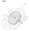
- FIG. 1 is a perspective view of the airflow-adjusting damper 10-1.
- the airflow-adjusting damper 10-1 comprises a hallow cylindrical metallic casing 12 and a vane portion 14 which is rotated in this metallic casing 12 for opening and closing a flow path P.
- the vane portion 14 contains two flat vane plates 16 which are overlaid mutually.
- These vane plates are designed in a size capable of closing a flow path P in the metallic casing 12 and formed in a substantially oval shape in which a long span thereof is longer than a diameter of the casing.
- These vane plates are formed in substantially same shape such that an outside circumference of a vane plate is slightly smaller than that of another vane plate.
- These vane plates 16 have a plurality of holes 18 which are distributed entirely thereon so as to secure opening for airflow.
- the number and shape of the plural holes 18 may be arbitrary and allocation intervals between the holes may be set also arbitrarily. However, because, when the entire flow path is opened or closed, the plural communicating openings are kept open, the number and allocation and the like of the holes must be set so that the communicating openings are fully opened/closed at least by sliding the vane plates. If the opening ratio is set so as to be large, sound deadening effect is high, however, because of a relation with control characteristic depending on air flow amount, the opening ratio is determined taking this into account.
- the hole diameter is desired to vary in plural kinds. This prevents generation of resonance producing a large noise which are caused by airflow having the same frequency. Further, the holes can obtain sound deadening effect only if they are provided in plurality.
- bearings 20 are mounted on two positions facing each other on a circumference which determines substantial diameter of the casing 12.
- a rotary shaft 22 is rotatably supported by this bearing 20. Then, the blade portion 14 is mounted on this rotary shaft and when the rotary shaft is rotated, the blade portion 14 is also rotated so as to open or close the flow path P in the casing 12.
- the blade portion 14 comprises a first and second substantially oval vane plates 16a, 16b.
- the first vane plate 16a is mounted onto the rotary shaft 22 in such a manner it always has a friction thereto so that it idlingly slides, through two metallic band mounting members 24 having a semi-circular portion each.
- the mounting of this vane portion to the rotary shaft may be of any structure as long as the vane portion can idle relative to the rotary shaft and is not restricted to the supporting method of the mounting member 24.
- the mounting member 24 is disposed such that the semi-circular portion thereof steps over the rotary shaft 22 and extension flat portions 26 thereof are fixed by welding or screwing or the like so that the first vane plate 16a is mounted on the rotary shaft idlingly.
- a feature of this embodiment is that the shared driving mechanism 28 which carries out opening/closing of the flow path of airflow and opening/closing of the plurality of the holes provided in the vane portion is provided.
- the rotary shaft 22 is rotatably provided across the aforementioned metallic casing 12 and the blade portion 14 is mounted onto this rotary shaft, so that the opening/closing of the airflow and opening/closing of the plurality of the holes are carried out by rotating the rotary shaft 22. Because this shared driving mechanism 28 enables opening/closing of the flow path P and opening/closing of the plurality of the holes provided in the vane portion by means of a single driving mechanism, material cost and production cost can be reduced. Further, because components can be concentrated on use, it is convenient in viewpoints of sharing, maintenance and administration of part members.
- guide pins 30 are provided so as to stand such that they go to the back of FIG. 2.
- the second vane plate 16a disposed so as to overlay the first vane plate 16b contains guide grooves 32 extending along the rotary shaft at positions corresponding to the fixing positions of the first vane plate 16a.
- the guide pins 30 provided on the mounting members 24 go through the guide grooves 32.
- each of the guide pin 30 is mounted a flat holding member 34 for release stopper which is larger than a width of the guide groove 32. These members hold both the vanes from being released from overlaid condition.
- the guide portion 36 comprises the guide pins 30 and guide grooves 32.
- the rotary shaft 22 has a driving pin 38 which is provided in radius direction of the rotary shaft 22 so as to intersect the length direction of the rotary shaft 22.
- This driving pins 38 are formed so that they goes through the first and second vane plate 16a, 16b while front ends thereof protrude.
- the first vane plate 16a contains a long groove 40 which is provided substantially perpendicular to the length direction of the rotary shaft 22 such that the driving pin 38 goes through the long groove 40.
- the second vane plate 16b also contains a long groove 42 penetrated by the driving pin 38.
- the long groove 42 is formed in a long shape in a direction different from the long groove provided in the first vane portion 16a. That is, the long groove 42 is formed at about 30° relative to the long groove 40 according to this embodiment.
- the blade portion 14 is formed in a substantially oval shape in which a long span thereof is longer than the diameter of the casing.
- the short span is designed to be substantially the same as the diameter of the cylindrical casing 12.
- a wall portion, which the long span contacts is a stopper portion 44.
- This stopper portion determines a position for closing by the blade portion 14. To determine the specified position clearly, it is permissible to mount a stopper member having L-shaped cross-section in the flow path. In particularly when the shape of the vane portion is real circle, this stopper member must be fixed.
- a change in flow rate relative to an angle of the vane portion when the flow path is fully closed is milder as compared to a case when the flow path is closed by positioning the vane portion substantially at right angle, or near proportional thereto thereby improving the flow rate control characteristic.
- the shared driving mechanism 28 comprises the rotary shaft 22 rotatably mounted in the metallic casing 12 and the blade portion 14 mounted on the rotary shaft 22.
- the blade portion 14 comprises the first vane plate 16a mounted idlingly to the rotary shaft 22 and the other vane plate 16b fixed slidably to the first vane plate.
- the shared driving mechanism 28 further comprises long grooves 40, 42 provided in the vane plates 16a, 16b respectively, the driving pin 38 which is fixed on the rotary shaft 22 in radius direction and goes through the long grooves 40, 42 in the overlaid vane plates 16a, 16b, and the stopper portion 44 for specifying a position in which the flow path P is closed by the vane portion 14.
- the shared driving mechanism 28 includes only the rotary shaft 22 and the driving pin 38 which is provided on the rotary shaft. Then, the long grooves 40, 42 are formed in the vane portion 14. Therefore, the structure is very simple and not only production thereof is very easy but also the material cost is cheap.
- the rotary shaft 22 is rotated so as to make the blade portion 14 close the flow path P and next, the rotary shaft is further rotated continuously from this flow path closing state so as to slide the vane plate without any electrical control means, thereby closing the plural holes 18.
- the driving pin 38 is moved in the long groove in the vane plate. Consequently, the vane portion is moved linearly directly by the driving pin 38.
- the mechanism for changing the rotary motion to linear motion is very simple and depends on interlocking motion. Therefore, no gear or belt mechanism is required thereby reducing production cost, facilitating maintenance and inspection, and further assuring the lowest fault ratio.
- a communicating urging member 46 exemplified by a coil spring is provided on the rotary shaft 22.
- This communicating urging member 46 is fit to the vane plates 16a, 16b so as to urge the vane plates 16a, 16b by spring so that the vane plates 16a, 16b overlay each other while the holes 18 correspond to each other to form each communicating hole.
- the vane portion 14 In usual operation for opening or closing of the flow path P, the vane portion 14 is rotated with the plural holes 18 opened and then, the flow path P is fully closed.
- the rotary shaft 22 When the rotary shaft 22 is further rotated, it is rotated against the spring urging force of the communicating urging member 46, so that the second vane plate is slid by the driving pin 38.
- the coil spring is utilized as the urging means in this embodiment, it is permissible to use a structure for applying a urging force in such a direction in which the communicating opening is formed by rubber or pneumatic pressure.
- the communicating urging member 46 is preferred to act also as a pressing spring which presses the first vane plate from above the second vane plate. Consequently, the second vane plate is prevented from slipping out.
- the plural holes 18 provided on the vane plates 16a, 16b are distributed almost entirely thereon. This enables divided slight amount of air to flow to the downstream in the entire flow path thereby preventing drift current in the downstream. Thus, even if this system is provided in the vicinity of an air outlet so that it faces an interior of a building, excellent airflow-adjusting function and rectifying function can be exerted.
- the present invention is basically characterized in that, the metallic casing 12 for forming the air flow path P inside thereof and the blade portion 14 which is rotated in the casing 12 for opening/closing the flow path P, are provided and the vane portion 14 comprises a plurality of the vane plates 16 which are overlaid, slidably mounted and contain a plurality of the holes 18.
- the airflow amount in the entire flow path can be adjusted by opening the vane portions with the holes 18 therein made in communication with each other so as to form communicating openings.
- the entire opening/closing is performed while always allowing fine amounts of airflow to go through those communicating openings. Therefore it is possible to effectively eliminate wind noise or other noises which may be caused by a sudden change of a large opening. Further, no drift current is produced and rectified flow can be allowed to go to the downstream.
- any shape cross section dampers having for example, a rectangular cross section may be used.
- a long circle shape is used in this example for the shape of the vane plate, it is permissible to use a real circle, oval shape, other circular shapes, rectangular, other polygon shape or any other shapes.
- Any driving means may be connected to the end portion protruding from the rotation shaft 22 shown in FIG. 1.
- a manual handle, driving motor or other driving mechanism For example, it is permissible to connect a manual handle, driving motor or other driving mechanism.
- Reference numeral 48 denotes an airflow-detecting sensor.
- the vane portions are held by the urging spring 46 so that the holes in the first vane plate 16a and the holes in the second vane plate 16b form communicating openings.
- the driving pins 38 are located at any of the end portions of the long grooves 40, 42 while penetrating therethrough.
- the vane portion 14 fully opens the flow path P with the first and second vane plates being overlaid, such that the vane portion 14 is set horizontally along the airflow.
- the vane portion 14 is gradually rotated from this state, the vane portion 14 is deviated in such a direction to close the flow path P.
- the bodies of the vane plates 16a, 16b act to decrease the airflow amount by resistance while allowing a slight amount of air to go to the downstream. Therefore, the following has been recognized through experiments. That is, there is not produced a large wind noise which may be caused when a conventional butterfly type vane plate are deviated so as to close the airflow path by throttling two upper and lower openings and a larger amount of airflow can be controlled under the same condition as compared to the conventional case.
- the blade portion 14 closes the flow path in such a manner that it is not at right angle to a flow direction of the flow path but oblique thereto as shown in FIG. 6.
- the respective vane plates 16a, 16b form communicating holes so that air flow can pass therethrough.
- airflow rate control by closing the air path by means of the blade portion 14 is achieved.
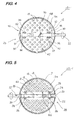
- FIG. 6 show a state in which the entire flow path P is closed but the respective holes 18 are still kept in communication with each other so as to keep opening.
- FIGs. 3, 5 show a complete closing state in which the secondary rotation is completed so that the communicating opening is closed. In an interval of rotation of the rotary shaft from a start of the secondary rotation shown in FIG. 6 to an end thereof, as shown in FIG.
- the driving pin 38 moves in the long grooves 40, 42 of the first and second vane plates 16a, 17b respectively, so that the second vane plate 16b is slid with respect to the first vane plate 16a in the length direction of the rotary shaft. Then, the complete closing state of the flow path as shown in FIG. 3 is obtained. Because during this secondary rotation, a motion of closing the communicating openings successively is carried out, the plural holes are closed in steps thereby making it possible to conduct fine adjustment of airflow accurately. Further, even in a state near complete closing, the fine division airflow is made to go across the entire vane plate and therefore no wind noise is produced, so that the complete closing of the flow path can be conducted silently. Further because until finally, airflow is distributed equally over the entire vane plate while the closing operation is carried out, no drift current is produced in the downstream. Further, the sensor provided in the upstream is not affected seriously, so that that sensor can exert its sensing function at a high precision.
- the airflow-adjusting damper according to the present invention is not restricted to the above-described embodiments.
- the rotary shaft is provided in a direction intersecting the flow path, it is permissible to provide a rotary shaft in the direction of the flow path by using gear system, conversion mechanism or the like.
- the basic structure is satisfied by comprising the casing and the vane portion which is rotated so as to open or close the flow path while the vane portion contains plural vane plates which are overlaid, mounted slidably and have a plurality of holes.
- the rotary shaft and sliding mechanism may be driven by different driving methods.
- Urging of the vane plates with respect to the rotary shaft by a urging spring according to the embodiment may be substituted by any type of spring mechanism.
- any of the vane plates of the vane portion may be provided slidably in a direction intersecting the rotary shaft.
- the number of the vane plates may be not only two but also three or more.
- the shape of the vane plate may be square or other polygonal shape. As already described above, the shape, allocation or the like of the holes may be set arbitrarily.
- the present invention may be applied to the airflow-adjusting damper which comprises the casing, the rotary shaft provided rotatably in the casing and vane portion which is rotated in the casing so as to open or close the flow path, while the vane portion contains vane plates which are overlaid, mounted slidably and have a plurality of holes. Further, it is permissible that each of the vane plates of the vane portion is mounted idlingly on the rotary shaft and an urging spring for urging the vane plates so that the plural holes form communicating openings is provided.
- FIGs. 8-14 an airflow-adjusting damper 10-2 according to a second embodiment of the present invention will be described with reference to FIGs. 8-14. With the same reference numerals applied to the same components, a description thereof is omitted.
- the blade portion 14 is provided on the rotary shaft 22 such that it is slidingly rotatable, the rotary shaft being supported rotatably by the casing 12.
- This vane portion comprises plural vane plates, which are overlaid mutually mounted slidably, and have a plurality of the holes 18.
- the vane plates 50a, 50b of the blade portion 14 are formed in the shape of real circle.
- This embodiment also contains the shared driving mechanism 28.
- This shared driving mechanism 28 comprises the rotary shaft 22 mounted rotatably on the casing 12 and the vane portion 14 mounted on the rotary shaft 22, the vane portion 44 having a first vane plate 50a mounted idlingly on the rotary shaft 22 and another vane plate 50b mounted slidably on the first vane plate, and the shared driving mechanism 28 further comprises long grooves 50a, 50b disposed in the vane plates 50a, 50b respectively, a driving pin 38 which is fixed to the rotary shaft 22 such that it directs in radius direction and an end of which is protruded through the long grooves 52, 54 in the vane plates overlaid, and a stopper portion 44 for determining a position for closing the flow path P by means of the blade portion 14.
- the shared driving mechanism 28 opens/closes the plural holes 18 by further rotating the rotary shaft 22 continuously from a state in which the flow path P is just closed.
- This embodiment is different from the previously described one in that the vane plate of a rotatable side, that is, the second vane plate 50b rotates with respect to the first vane plate 50a in such a manner that the second vane plate 50b slides thereon.
- the vane plates 50a, 50b of the blade portion 14 are formed in a circular shape. Their substantial center is supported by a rivet 51 and both the vane plates are structured so as to rotate relative to each other around this rivet 51 in such a manner that the faces thereof rub each other.
- a long groove 52 is formed at a position apart from the center of the first vane plate 50a by a distance of S in the length direction such that it intersects the rotary shaft. If the S is set so as to be long, the rotation angle of the vane plate becomes small. Thus, this S is determined depending on the size and allocation of the holes provided in the vane plate so as to enable appropriate opening/closing thereto.
- the long groove 54 in the second vane plate 50b which slidingly rotates with respect to the first vane plate 50a is formed so as to be longer than at least the diameter of the driving pin 38 in the radius direction of the second vane plate 50b.
- the plural holes 18 are made to communicated with each other so as to form the communicating openings and after the air path is closed, any of the vane plates is slid so as to close the communicating openings.
- a urging spring is provided between the second and first vane plates or other supporting portion so as to keep the holes 18 always open.
- the blade portion 14 is provided on the rotary shaft 22 rotatably supported by the metallic casing 12 such that the blade portion 14 is slidingly rotatable.
- the vane portion comprises plural vane plates which are overlaid, mounted slidably and contain a plurality of the holes 18 each. Consequently, the operation and effect of the second embodiment are the same in viewpoints of sound deadening effect, fine adjustment of airflow, rectifying function, improvement of sensing performance of an airflow sensor and the like, as the first embodiment.
- opening/closing of the flow path P and opening/closing of the plural holes 18 by only the driving pin can be achieved by a single driving system, so that easiness of production, low material cost, and easiness of modification, maintenance and inspection or the like are attained in the second embodiment, which are the same operation and effect as the first embodiment.
- circular grooves 55 are disposed for guiding the circular rotation of the second vane plate 50b. Then, a flat rivet 57 is inserted into each of the circular grooves and fixed therein and an end of the flat rivet 57 is fixed on the first vane plate 50a.
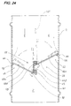
- FIGs. 15-25 An airflow-adjusting damper according to a third embodiment of the present invention will be described with reference to FIGs. 15-25.
- the same reference numerals are attached to the same components and a description thereof is omitted.
- rotary shafts 58, 60 are rotatably journaled so as to cross over the casing.
- Vane portions 62, 64 are attached to the rotary shafts 58, 60.
- the vane portions 62, 64 are journaled on the rotary shafts 58, 60 so as to be able to idle.
- Each of the vane portions is formed in semi-circular shape. They are installed so as to open or close a half of the flow path P in hinge style. That is, the rotary shafts 58, 60 are provided so as to transverse the flow path with respect to the direction of flow in the flow path and these rotary shafts are installed in series with respect to the flow path.
- the vane portions 62, 64 are provided so that they rotate in opposite directions to each other to close the flow path.
- the first and second vane plates 66a, 66b, 68a, 68b of the vane portions 62, 64 at least the first vane plates 66a, 68a are formed so as to contain circular vertexes 70a, 72a formed on each of circumferences, located with a longer distance than a radius of the flow path P.
- the vane portions 62, 64 are rotated from full opening state in which they are in parallel to the flow path to reach full closing state in which they are opened at about 70° with respect to the direction of flow. Therefore, in this embodiment, circular portions formed on the vane portions 62, 64 which make contact with an inside wall of the flow path act as a stopper portion 44 which determines closing positions of the vane portions.
- a stay 65 is stretched between both the rotary shafts so as to clog a gap therebetween.
- the semi-circular vane portions 62, 64 are placed at an interval in the direction of the flow path and these vane portions are opened or closed in hinge style with their journal positions being deviated with an interval. Then, to clog this interval due to the deviation, the stay 65 is provided.
- the flow rate control characteristic can be improved as compared to the case in which the flow path is opened or closed by rotating a single vane portion.
- the aforementioned stay 65 is formed of atypical U-shaped frame plate and mounted on the rotary shafts 58, 60 in such a manner that ends of the stay 65 are fixed by shaft rings 74 which allow the rotary shafts 58, 60 to idlingly rotate, thereby clogging the gap formed between these rotary shafts.
- first vane plates 66a, 66b are fixed to each of the sleeves 76.
- glass wool or foamed material members 78 are fixed to the circular portions of the first vane plates 66a, 66b for air-tightness or noise damping or the like by such a means as adhesive or the like.
- the vane portions 62, 64 are installed on the rotary shafts 58, 60 rotatably supported by the casing 12 such that they are rotatable slidingly relative to each other and the these vane portions are overlaid, mounted slidingly and have a plurality of the vane plates containing a plurality of the holes 18.
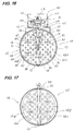
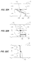
- FIGs. 22, 23 are longitudinal sectional views for describing the operation taken from the downstream of the airflow, that is, the first vane plate side.
- second vane plates 66b, 68b slidingly such that bottom ends thereof are nipped between the rotary shafts 58, 60 and the first vane plates 66a, 68a which close the flow path P at a sharp angle with respect to the direction of air flow from the upstream thereof.
- FIGs. 16, 17 are longitudinal sectional views for describing the operation taken from the upstream of the airflow, that is, the second vane plate side.
- the second vane plates 66b, 68b are provided so as to overlay the first vane plates 66a, 68a so that they can slide smoothly in a direction intersecting the rotary shafts 58, 60.
- the bottom portions of the first and second vane plates 66a, 66b, 68a, 68b or the supported portions by the rotary shafts 58, 60 contain long grooves 84, 86 extending in a direction intersecting the rotary shafts and each of the first and second vane plates have two grooves.
- the long grooves in the first vane plates 66a, 68a which are not slid are set so as to be long enough for the driving pins 38 to move for sliding the second plates.
- the long grooves in the second vane plates 66b, 68b have only to have such a length that the driving pins 38 go therethrough to be able to slide the second vane plates on the first vane plate by hooking.
- Each of the rotary shafts 58, 60 has driving pins 38 which are fixed on these rotary shafts 58, 60 so as to direct in the radius direction and go through each of the long grooves provided in the overlaid plural vane plates so that an end thereof protrudes.
- the rotary shafts 58, 60 have coil springs 88 as an urging spring, which always urge the vane portions 62, 64 in the direction of closing the flow path.
- the coil springs 88 also act at the same time to press the second vane plates against the first vane plates with an end of the first vane plate matching each of the second vane plates 66b, 68b.
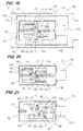
- the long grooves 84, 86 are set to a length including the moving range R1 of the driving pin corresponding to an entire motion of closing the holes 18 fully by making the driving pin hook the second vane plates 66b, 68b so as to slide the second vane plates 66b, 68b. That is, when the driving pin 38 moves from position x to position y in the long groove, the plural holes 18 are closed or opened all at once. The pin 38 closes the holes 18 fully at the position y as shown in FIG. 25B and opens them fully at the position x. When the driving pin 38 further rotates in the direction of opening the holes 38, the flow path is opened while keeping the holes 18 fully open, up to its full opening state.
- the shared driving mechanism 28 is provided so that the rotary shafts 58, 60 are rotatably provided to cross over the casing 12 and the vane portions 62, 64 are provided on the rotary shafts such that by rotating the rotary shafts, opening/closing of the flow path and opening/closing of the plurality of the holes are carried out at the same time.
- opening/closing of the flow path and opening/closing of the plural holes are carried out by rotating the rotary shafts 58, 60 so that they are conducted by a single driving system.
- the basic structure comprises the rotary shafts and driving pins, the structure is very simple, and therefore easy to produce, can be formed with minimized parts, and maintenance and control thereof are very simple.
- the shared driving mechanism 28 comprises the rotary shafts 58, 60 mounted rotatably on the casing 12 and the vane portions 62, 64 mounted on the rotary shafts 58, 60, the vane portions 62, 64 having first vane plates 66a, 68a mounted idlingly on the rotary shafts 58, 60 and another vane plates 66b, 68b mounted slidably on the first vane plates, and the shared driving mechanism 28 further comprises long grooves 84, 86 disposed in the vane plates 66a, 66b, 68a, 68b respectively, driving pins 38 which are fixed to the rotary shafts 58, 60 such that they direct in radius direction and end of which are protruded through the long grooves 84, 86 in the vane plates overlaid, and stopper portions 44 for determining positions for closing the flow path P by means of the blade portions 62, 64.
- An effect of provision of the shared driving mechanism is the same as in the first embodiment. Because opening/closing of the flow path P and opening/closing of the plural holes provided in the vane portions are carried out by a single driving mechanism, material cost and production cost are cheap. Because structure members are concentratedly used, it is convenient in viewpoints of sharing, maintenance and control of the part members.
- the shared driving mechanism 28 basically comprises only the rotation shaft and the driving pin 38 installed on the rotation shaft. Therefore, the structure is very simple, production thereof is easy and the material cost can be reduced to very cheap level.
- the shared driving mechanism 28 rotates the rotary shafts 58, 60 further continuously from the state in which the flow path P has been just closed, so as to slide the vane plates to open/close the plural holes 18. Therefore, there is no waste in motion and the operation thereof is secure. Because the vane portions 62, 64 are rotated in opposite directions to each other to open/close each of half of the flow path. To achieve simultaneous opening/closing of these vane portions, a synchronous opening/closing mechanism 90 is provided.
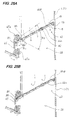
- the synchronous opening/closing mechanism 90 is mounted outside of the metallic casing 12 which contains ends of the rotary shafts 58, 60.
- the synchronous opening/closing mechanism 90 is incorporated in a box formed of a fixing base 92, a frame 94 and a cover 96.
- the synchronous opening/closing mechanism 90 comprises cam members connected to the rotary shafts 58, 60 and slide mechanism which engages the cam member and rotates the same cam member inversely.
- eccentric cams 98 having substantially egg-shaped cross section which are cam members are fixed to end portions of the rotary shafts 58, 60 and an input pin 100 is provided on an isolated end portion of each cam 98 on the external side with respect to the casing 12.
- the input pins are turned in opposite directions to each other with respect to the rotary shafts 58, 60 so that the eccentric cams 98 are rotated just like in crank motion.
- a slide plate 104 as a sliding mechanism is supported by supporting shafts 102 so as to direct along the direction of airflow. That is, the rectangular slide plate 104 has guide long grooves 106 which are formed long in the direction of air flow.
- the supporting shafts 102 installed on the fixing base 92 go through the guide long grooves 106 and are fixed each with a locking head bolt from above the groove 106 in such a condition that a cylinder is provided below and the slide plate 104 is slidably mounted on that cylinder in the flow direction.
- the slide plate 104 contains two engaging grooves 108 which are provided in a direction substantially perpendicular to the sliding direction and at an interval separating them.
- the input pins 100 corresponding to the rotary shafts 58, 60, installed on the eccentric cams 98 go through the engaging grooves 108 so that they protrude. Consequently, when the slide plate 104 is slid in the direction of the air flow, the input pins 100 move within the guide long grooves 106?? so that they take circular motion in the range r around the rotating shafts 58, 60. Then, this range in which the pins 100 move a range in which the rotary shafts 58, 60 are rotated as such a range in which at least the vane plates 62, 64 opens or closes the flow path P.
- the slide drive mechanism 112 based on the slide plate 104 comprises a screw shaft 114 which is mounted on the frame 94 so as to extend in the direction of the sliding motion of the slide plate 104, a nut member 116 which is engaged with this screw shaft 114 so that it advances or retracts in the sliding direction of the slide plate, a slide adjusting plate 118 the substantial center portion of which is supported by a bottom face of the nut member and which is provided in a direction of intersecting the screw shaft 114, and coil springs 120 which are stretched between the slide plate and the slide adjusting plate 118 so as rotate the slide adjusting plate 118 counterclockwise.
- the aforementioned drive receiving pins 110 are located on edges of the slide adjusting plate 118 such that front ends thereof are protruded above the adjusting plate. Therefore, against the pulling force of the coil springs 120, the drive receiving pins 110 hold the adjusting plate 118 in a condition substantially perpendicular to the screw shaft 114. Consequently, the nut member 116 can move linearly along the screw shaft 114 and at the same time, the linear motion of the input pins 100 is converted to rotary motion smoothly while a shock produced by the linear motion is absorbed by the elasticity of the coil springs.
- reference numeral 122 denotes a drive motor the driving shaft of which is fixed on the screw shaft 114.
- Reference numeral 124 denotes an airflow rate detecting sensor which is provided in the upstream relative to the vane portions 62, 64.
- the vane portions 62, 64 are disposed along the flow direction.
- the driving pins 38 are maintained at the position x in the long grooves 84, 86 so as to fully open the holes 18, and then with the holes 18 fully open, the vane portions are rotated from the full open condition to the full close condition.
- the opening/closing operation of the rotary shafts 58, 60 is carried out by the cam members, slide mechanism and slide drive mechanism of the synchronous opening/closing mechanism 90, which rotates the vane portions 62, 64 synchronously in opposite directions to each other so as to open or close the flow path.
- the synchronous opening/closing mechanism is not restricted to a structure of this embodiment but any structure is permitted as long as it can rotate the rotary shafts 58, 60 synchronously in opposite directions to each other.
- the third embodiment comprises the casing in which an air path is formed internally and vane portions which are rotated in the casing so as to open/close the flow path, the vane portions containing a plurality of the vane plates which are overlaid, mounted slidably and have a plurality of the holes. Further, when opening/closing the entire flow path by means of the vane portions, the holes of corresponding vane plates are made to communicate with each other so as to form communicating openings. After the air path is closed, any of the vane plates is slid so as to close the communicating openings.
- the shared driving mechanism is provided in which the rotary shafts are rotatably provided so as to cross over the casing and the vane portions are mounted on the rotary shafts, so that, by rotating the rotary shafts, the opening/closing of the flow path and opening/closing of the plural holes are carried out.
- this shared drive mechanism by rotating further the rotary shafts continuously from the condition in which the flow path is closed, the vane plates are slid to open/close the plurality of the holes.
- the operation and effect of the present embodiment includes ability to prevent generation of wind noise and other noise effectively, improvement of the flow rate control function in the case when the vane portions are almost fully closed, which is the most difficult and important work, ability of preventing drift current, carrying out rectification and being installed near an air conditioner at the end of a system, improvement of airflow rate detecting accuracy, and that not so many sensors are required.
- the same operation and effect as the first embodiment can be obtained.
- two pairs of the vane portions are provided on two rotary shafts, for example, it is permissible to so construct that 3, 4, 5, 6, ...
- pairs of the vane portions which comprise overlaid vane plates having a plurality of holes, are rotatably supported in a casing having a square cross section and opened/closed through link mechanism at the same time while opening/closing of the holes is carried out by sliding the vane plates at the same time when opening/closing of the flow path is carried out.
- the airflow-adjusting damper of the fourth embodiment comprises the casing 12 for forming airflow internally and the vane portions 14 which are rotated in the casing 12 so as to open/close the flow path P, the vane portions 14 containing a plurality of the vane plates 16a, 16b which are overlaid, slidably mounted and have plural holes 18.
- the plural holes 18 are made to communicate with each other so as to form communicating opening and after the air path P is closed, any of the vane plates 16a, 16b is slid to close the communicating opening.
- the shared drive mechanism 28 is provided in which the rotary shafts 22 are rotatably mounted so as to cross over the casing 12 and the vane portion 14 is provided on the rotary shafts 22 and by rotating the rotary shafts 22, opening/closing of the flow path and opening/closing of the plural holes are carried out. Further the shared drive mechanism 28 is so constructed as to slide the vane plates to close the plural holes 18 by rotating further the rotary shafts continuously from the condition in which the flow path is closed.
- the vane portion 14 for opening/closing the flow path P is a pair and the vane plates 16a, 16b which have real circular shape substantially corresponding to an internal diameter of the cylindrical casing are rotated so as to open or close the flow path P.
- the shared drive mechanism 28 comprises the rotary shafts 22 rotatably provided in the casing 12 and the vane portion 14 mounted on the rotary shafts, the vane portion containing the first vane plate 16a which is idlingly mounted on the rotary shaft 22 and the second vane plate 16b which is slidably fixed to the first vane plate 16a.
- the rotary shaft 22 contains a screw portion 126 and further a retracting mechanism 126 which engages this screw portion so as to slide any of the vane plates is provided.
- the rotary shaft 22 is rotatably supported by the bearing 20 fixed on the casing 12 so as to cross over the flow path.
- the first vane plate 16a of the vane portion 14 is idling mounted on this rotary shaft 22 through the mounting member 24 comprising a shaft band.
- a screw groove which is the screw portion 126 and on the right and left sides of the screw portion are mounted sleeves 130 having predetermined length.
- the structure for setting the length of the screw portion is not restricted to this method. It is permissible to disable the motion of the nut member by the length and width of the cutout hole which will be described later, and any other structure may be permitted.
- a rectangular cutout portion 132 is formed at a position corresponding to the screw portion 126 of the rotary shaft 22 of the first vane plate 16a.
- a nut member 134 which engages the screw portion 126 and retracts is provided and the proximal end of this nut member is fixed on the second vane plate 16b through the cutout portion 132.
- a tension spring 138 one end of which is fixed to the first vane plate 16a and the other end of which is fixed to a supporting member 136 provided in the flow path is stretch so that the first vane plate is always urged in the direction of closing the flow path P.
- the stopper member (44) having L-shaped cross section is provided in the flow path so that the vane portion 14 is restricted in a direction perpendicular to the air flow when the flow path is fully closed.
- the tension spring is not restricted to this embodiment and for example, it is permissible to mount the coil spring on the rotary shaft so that the spring end is urged in the direction of closing the flow path.
- the retracting mechanism 128 includes the aforementioned nut member and an urging member 138 exemplified by the tension spring.
- the length of the screw portion 126 must only be set to such a length at least enabling a plurality of the holes 18 provided on the vane plate to be opened or closed.
- the vane portion 14 make contact with the stopper member 44 so that the vane portion 14 is blocked.
- the nut member 134 advances on the screw portion 126, so that the second vane plate 16b is slid along the rotation shaft thereby closing the holes fully.
- the vane plate is slid by advancing or retracting the nut member fixed on the vane plate of the sliding side which engages the screw portion formed on the rotary shaft, thereby opening/closing the plurality of the holes 18.
- the operation thereof is carried out securely.
- the airflow-adjusting damper of this embodiment comprises the casing in which the airflow path is formed internally and the vane portion which is rotated in the casing so as to open/close the flow path, the vane portion containing plural vane plates which are overlaid, slidably mounted and have a plurality of holes; two rotating shafts 58, 60 are provided and two vane portions 62, 64 rotatably supported in the flow path are supported thereon; the vane plates are semi-circular and a length from the proximal portion to the vertex of the circumference is longer than the radius of the flow path and the vane portions are maintained at a sharp angle relative to the direction of flow when the flow path is fully closed; the shared drive mechanism is provided; the shared drive mechanism 28 comprises the rotary shafts 58, 60 rotatably mounted in the casing 12 and the vane portions 62, 64 rotatably mounted on the rotary shafts, the vane portions 62, 64 including the first vane plates
- the shared drive mechanism 28 has double rotary shafts.
- the gear mechanism makes the double shafts carry out the rotation corresponding to the opening/closing of the flow path by the vane portions and rotation corresponding to the opening/closing of the plural vanes of the vane portions in series operation, so that these operations are shifted continuously.
- the motor drive shaft carries out the opening/closing of the flow path and the opening/closing of the plural holes at the same rotation speed.
- a gear mechanism 142 which engages the pinion gear 140 connected to a motor drive shaft (not shown) is mounted on shaft ends of the rotation shafts 58, 60 outside of the casing 12.
- These rotation shafts and gear mechanisms contain the same structure components each, therefore one rotation shaft and gear mechanism will be described.
- the rotation shaft 58 contains double shaft structure comprising a middle shaft 58a and an outer shaft 58b which is mounted on an external circumference thereof and rotated slidingly freely.
- a driving pin 38 is fixed on the middle shaft 58b so as to direct in the radius direction and an end thereof goes through the long grooves 84, 86 of the vane plates 66a, 66b.
- the outer shaft 58b On an external face of the middle shaft 58a is mounted the outer shaft 58b such that it is movable relative to the middle shaft and coaxial therewith.
- the cutout groove 144 is formed at a position corresponding to the drive pin 38 mounting position of the middle shaft 58b as shown in FIG. 38.
- the drive pin 38 of this middle shaft 58a goes through the cutout groove 144 and further goes through the vane plates 66a, 66b so as to protrude. Rotation of this drive pin 38 opens or closes the plural holes 18 in the vane portion.
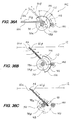
- the gear mechanism 142 installed on an end of the rotation shaft 58 comprises a first gear 146 and a second gear 148.
- the first gear 146 is formed in a substantially fan shape and a circular proximal portion is fixed to the middle shaft 58a.
- An interlocking pin 150 is raised from the first gear 146 (provided on a back side of FIG. 36A). When the second gear is rotated, this interlocking pin is pushed so that the first gear is synchronously rotated in the same direction.
- On a fan-like circular portion of this first gear 146 is formed an engaging portion 152 having gear teeth for engaging a pinion gear 140.
- the middle shaft 58a is also rotated.
- the drive pin 38 is driven so as to rotate the second vane plate 66b which is a sliding vane plate in such a direction that the plural holes 18 are closed.
- the second gear 148 is also formed in the substantially fan-like circular shape and fixed to ends of the rotation shafts such that it overlies the first gear with a gap in the length direction of the rotation shaft 58. That is, the proximal portion of the second gear 148 is fixed to the outer shaft 58b. Then, an engaging portion 154 which will engage the pinion gear 140 is provided on the circumference.
- the interlocking pin 150 of the first gear 146 is installed in a direction intersecting the rotation direction, within a rotation range of the engaging portion 154 of the second gear 148.
- first vane plate 66a is fixed to the outer shaft 58b and the second vane plate 66b is slidably provided in a direction intersecting the rotation shaft such that it overlies the first vane plate 66a.
- the outer shaft is rotated and accompanyingly, the first vane plate 66a is rotated in the flow path.
- the vane portion 62 directs to the upstream of airflow as shown by the solid line such that it is fully opened.
- the drive pin 38 fixed on the middle shaft 58a is located at the left end shown by the solid line.
- the second vane plate 66b of the sliding side is slid so as to open the plural holes 18 fully.
- the engaging portion 154 of the second gear engages the second gear 148 and rotates it in the clockwise direction.
- a strike portion located on an edge of the corner portion of the second gear pushes the interlocking pin 150, so that the first and second gears are rotated synchronously in the clockwise direction without changing the relative position between the middle shaft 58a and outer shaft 58b. Because the relative rotation position between the middle shaft and outer shaft is not changed, the drive pin 38 is not moved in the cutout groove 144 and the vane portion 64 is rotated in the direction of closing the flow path with the plural holes 18 fully open.
- opening of the holes 18 and opening of the flow path are carried out in reverse order and both the gears are returned to the position shown in FIG. 36A.
- opening/closing of the flow path and opening/closing of the plural holes are carried out by interlocking and series operation of the gears, so that the operation of the vane portions is conducted securely thereby achieving high reliability.
- the double shaft structure including the middle shaft and outer shaft is applied in this embodiment, the interlocking of the gears to drive the vane portions in the casing can be performed smoothly.
- the structure for connecting two driving movements in series, particularly a structure for continuously driving the two driving motions is simplified and production of this system is facilitated.
- the structure of the fifth embodiment is the same as that of the third embodiment and the same operation and effect can be attained.
- the flow rate control characteristic can be improved as compared to the case in which a pair of the vane plates are supported so as to open/close the flow path.
- the rotation shafts in series in the flow path, the pressure loss in the flow path P is minimized so as to raise the airflow rate control characteristic.
- the structure in which the vanes are overlaid with each other and the plural vanes can be slidingly opened/closed is the same, and an operation and effect thereof are the same as the first embodiment.
- the same operation and effect as the first embodiment include ability of preventing wind noise and other noise effectively, improvement of flow rate control function in the case when the vane portions are fully closed, which is the most difficult and important point, ability of preventing drift current, carrying out rectification and being installed near an air conditioner at an end of an system, improvement of the airflow detecting accuracy, and that a minimum number of sensors can satisfy requirement.
- FIGs. 39, 42 The structure of the vane portion 14 and the other structure are the same for example, the first embodiment.
- the same reference numerals are attached to the same components and a description thereof is omitted.
- the shared drive mechanism 28 is provided at each vane portion of a multi-vane type damper.
- the damper casing 12 is square and four square vane portions 14 are rotatably supported by the rotation shafts 22 so as to open or close the air flow path having square cross section.
- the multi-vane type damper of this embodiment are provided the vane portions 14 in which the plural vane plates 16a, 16b ... are overlaid so that they are freely slidable.
- FIG. 39 shows multi-vane type damper of opposing vane type in which two vane portions 14 are opened/closed such that they oppose each other.
- Each vane portion contains the shared drive mechanism 28 for carrying out opening/closing of the airflow path and opening/closing of the plural holes 18 by rotating the rotary shaft.
- link mechanism 156 is utilized.
- the rotation shaft 22R is rotated, the rotation shafts 22S, 22T, 22U are synchronized therewith so that the other rotation shafts 22S, 22T are rotated inversely.
- the 22R is connected to a motor drive shaft, the vane portions supported by other rotation shafts are rotated in opposite direction so that the vane plates 16a, 16b are slid thereby opening/closing the plural holes 18.
- the conventional link mechanism is used for synchronous opening/closing, it is permissible to drive each vane plates separately.
- FIG. 40 shows a multi-vane damper of parallel vane type.
- the vane portions are opened or closed synchronously with the link mechanism 156 so as to open/close the plural holes 18.
- the vane plates are slid along the rotation shafts by means of the drive pins in the same manner as the first embodiment.
- the link mechanism 156 of this embodiment may be made to synchronize by using a belt, chain, gear or the like.
- the shared drive mechanism is attached to each vane portion of the multi-vane type damper, it is permissible to construct that the second vane plates are allowed to slide in a direction intersecting the rotary shaft as shown in the third embodiment or it is permissible to form the rotary shaft with multiple shafts so that opening/closing of the airflow path and opening/closing of the plural holes are shifted by the gear mechanism, like the third embodiment.
- the airflow-adjusting damper of the present invention is not restricted to the above described embodiments but any modification may be made within a scope not departing from the gist of the present invention mentioned in claims thereof.
Landscapes
- Engineering & Computer Science (AREA)
- Chemical & Material Sciences (AREA)
- Combustion & Propulsion (AREA)
- Mechanical Engineering (AREA)
- General Engineering & Computer Science (AREA)
- Air-Flow Control Members (AREA)
Priority Applications (1)
| Application Number | Priority Date | Filing Date | Title |
|---|---|---|---|
| EP97122079A EP0924475A1 (fr) | 1997-12-15 | 1997-12-15 | Clapet pour régler le débit d'air |
Applications Claiming Priority (1)
| Application Number | Priority Date | Filing Date | Title |
|---|---|---|---|
| EP97122079A EP0924475A1 (fr) | 1997-12-15 | 1997-12-15 | Clapet pour régler le débit d'air |
Publications (1)
| Publication Number | Publication Date |
|---|---|
| EP0924475A1 true EP0924475A1 (fr) | 1999-06-23 |
Family
ID=8227801
Family Applications (1)
| Application Number | Title | Priority Date | Filing Date |
|---|---|---|---|
| EP97122079A Withdrawn EP0924475A1 (fr) | 1997-12-15 | 1997-12-15 | Clapet pour régler le débit d'air |
Country Status (1)
| Country | Link |
|---|---|
| EP (1) | EP0924475A1 (fr) |
Cited By (19)
| Publication number | Priority date | Publication date | Assignee | Title |
|---|---|---|---|---|
| GB2371357A (en) * | 2000-11-24 | 2002-07-24 | Halton Oy | An air conditioner terminal device with air mixing control for a room |
| US6715538B2 (en) | 2000-11-24 | 2004-04-06 | Halton Oy | Supply air terminal device |
| EP1460352A1 (fr) * | 2003-03-18 | 2004-09-22 | Tri-Air Innovations Limited | Régulateur d'écoulement d'air et registre coupe-feu dans un canal de circulationd'air |
| FR2876434A1 (fr) * | 2004-10-11 | 2006-04-14 | Technofan Sa | Dispositif d'obturation d'une conduite et ensemble de ventilation incluant un tel dispositif |
| DE102006039238B4 (de) * | 2005-08-26 | 2009-04-30 | Smc K.K. | Strömungsmesser |
| US20100126340A1 (en) * | 2008-11-24 | 2010-05-27 | Dust Control Technology, Inc. | System and Method of Controlling Dust and/or Odors with a Blower Unit and a Deployable Baffle Member |
| WO2010110723A1 (fr) * | 2009-03-27 | 2010-09-30 | Inventiair Ab | Dispositif de régulation d'écoulement d'air |
| CN102359606A (zh) * | 2011-09-15 | 2012-02-22 | 上海朗诗建筑科技有限公司 | 带孔风阀 |
| EP2428743A1 (fr) * | 2010-09-10 | 2012-03-14 | TROX GmbH | Boîte de raccordement pour un système de canal d'une installation aéronautique ou climatique |
| US8469783B2 (en) | 2006-01-16 | 2013-06-25 | Halton Oy | Supply air terminal device and method for regulating the airflow rate |
| CN104848510A (zh) * | 2015-04-30 | 2015-08-19 | 华北水利水电大学 | 一种适用于远距离送风的冬夏两用送风口 |
| CN109084070A (zh) * | 2018-11-01 | 2018-12-25 | 山东龙腾电力科技有限公司 | 一种防爆型通风柜风阀传动机构 |
| CN111442149A (zh) * | 2020-05-05 | 2020-07-24 | 合肥丁点网络科技有限责任公司 | 一种消声风管风速均匀处理安装机构 |
| US10989439B2 (en) | 2017-07-13 | 2021-04-27 | Air Distribution Technologies Ip, Llc | Damper assembly |
| EP3916317A1 (fr) * | 2020-05-29 | 2021-12-01 | Rf-Technologies nv | Élément de ventilation comprenant un ou plusieurs volets rotatifs |
| US11402111B2 (en) | 2016-11-03 | 2022-08-02 | Air Distribution Technologies Ip, Llc | Staged damper system |
| US11566794B2 (en) * | 2017-04-28 | 2023-01-31 | Samsung Electronics Co., Ltd. | Air conditioner |
| JP2024031028A (ja) * | 2022-08-25 | 2024-03-07 | 空研工業株式会社 | ダンパ装置 |
| CN119412568A (zh) * | 2025-01-08 | 2025-02-11 | 山东瀚江环保科技有限公司 | 一种自动调压的耐磨阻力平衡器及管路系统 |
Citations (2)
| Publication number | Priority date | Publication date | Assignee | Title |
|---|---|---|---|---|
| JPH08327135A (ja) * | 1995-05-26 | 1996-12-13 | Kyoritsu Eatetsuku Kk | 風量調整ダンパー |
| JPH08327134A (ja) * | 1995-05-26 | 1996-12-13 | Kyoritsu Eatetsuku Kk | 風量調整ダンパー |
-
1997
- 1997-12-15 EP EP97122079A patent/EP0924475A1/fr not_active Withdrawn
Patent Citations (2)
| Publication number | Priority date | Publication date | Assignee | Title |
|---|---|---|---|---|
| JPH08327135A (ja) * | 1995-05-26 | 1996-12-13 | Kyoritsu Eatetsuku Kk | 風量調整ダンパー |
| JPH08327134A (ja) * | 1995-05-26 | 1996-12-13 | Kyoritsu Eatetsuku Kk | 風量調整ダンパー |
Non-Patent Citations (1)
| Title |
|---|
| PATENT ABSTRACTS OF JAPAN vol. 097, no. 004 30 April 1997 (1997-04-30) * |
Cited By (29)
| Publication number | Priority date | Publication date | Assignee | Title |
|---|---|---|---|---|
| US6715538B2 (en) | 2000-11-24 | 2004-04-06 | Halton Oy | Supply air terminal device |
| GB2371357B (en) * | 2000-11-24 | 2004-11-24 | Halton Oy | Supply air terminal device |
| US7000688B2 (en) | 2000-11-24 | 2006-02-21 | Halton Oy | Supply air terminal device |
| GB2371357A (en) * | 2000-11-24 | 2002-07-24 | Halton Oy | An air conditioner terminal device with air mixing control for a room |
| EP1460352A1 (fr) * | 2003-03-18 | 2004-09-22 | Tri-Air Innovations Limited | Régulateur d'écoulement d'air et registre coupe-feu dans un canal de circulationd'air |
| FR2876434A1 (fr) * | 2004-10-11 | 2006-04-14 | Technofan Sa | Dispositif d'obturation d'une conduite et ensemble de ventilation incluant un tel dispositif |
| DE102006039238B4 (de) * | 2005-08-26 | 2009-04-30 | Smc K.K. | Strömungsmesser |
| US8469783B2 (en) | 2006-01-16 | 2013-06-25 | Halton Oy | Supply air terminal device and method for regulating the airflow rate |
| US20100126340A1 (en) * | 2008-11-24 | 2010-05-27 | Dust Control Technology, Inc. | System and Method of Controlling Dust and/or Odors with a Blower Unit and a Deployable Baffle Member |
| US8182585B2 (en) * | 2008-11-24 | 2012-05-22 | Dust Control Technology, Inc. | System and method of controlling dust and/or odors with a blower unit and a deployable baffle member |
| WO2010110723A1 (fr) * | 2009-03-27 | 2010-09-30 | Inventiair Ab | Dispositif de régulation d'écoulement d'air |
| EP2428743A1 (fr) * | 2010-09-10 | 2012-03-14 | TROX GmbH | Boîte de raccordement pour un système de canal d'une installation aéronautique ou climatique |
| US20120060956A1 (en) * | 2010-09-10 | 2012-03-15 | Lukas Zwiernik | Connection box for a duct system in a ventilation or air-conditioning installation |
| CN102563826A (zh) * | 2010-09-10 | 2012-07-11 | 特洛克斯有限责任公司 | 室内空气技术或空气调节技术的设备的通道系统的联接盒 |
| CN102359606A (zh) * | 2011-09-15 | 2012-02-22 | 上海朗诗建筑科技有限公司 | 带孔风阀 |
| CN104848510A (zh) * | 2015-04-30 | 2015-08-19 | 华北水利水电大学 | 一种适用于远距离送风的冬夏两用送风口 |
| CN104848510B (zh) * | 2015-04-30 | 2017-04-05 | 华北水利水电大学 | 一种适用于远距离送风的冬夏两用送风口 |
| US11402111B2 (en) | 2016-11-03 | 2022-08-02 | Air Distribution Technologies Ip, Llc | Staged damper system |
| US12025326B2 (en) | 2016-11-03 | 2024-07-02 | Air Distribution Technologies Ip, Llc | Staged damper system |
| US11566794B2 (en) * | 2017-04-28 | 2023-01-31 | Samsung Electronics Co., Ltd. | Air conditioner |
| US10989439B2 (en) | 2017-07-13 | 2021-04-27 | Air Distribution Technologies Ip, Llc | Damper assembly |
| CN109084070B (zh) * | 2018-11-01 | 2023-10-27 | 山东龙腾电力科技有限公司 | 一种防爆型通风柜风阀传动机构 |
| CN109084070A (zh) * | 2018-11-01 | 2018-12-25 | 山东龙腾电力科技有限公司 | 一种防爆型通风柜风阀传动机构 |
| CN111442149A (zh) * | 2020-05-05 | 2020-07-24 | 合肥丁点网络科技有限责任公司 | 一种消声风管风速均匀处理安装机构 |
| BE1028358B1 (nl) * | 2020-05-29 | 2022-01-10 | Rf Tech Nv | Ventilatie-element met een of meerdere roteerbare klepbladen |
| EP3916317A1 (fr) * | 2020-05-29 | 2021-12-01 | Rf-Technologies nv | Élément de ventilation comprenant un ou plusieurs volets rotatifs |
| JP2024031028A (ja) * | 2022-08-25 | 2024-03-07 | 空研工業株式会社 | ダンパ装置 |
| JP7787522B2 (ja) | 2022-08-25 | 2025-12-17 | 空研工業株式会社 | ダンパ装置 |
| CN119412568A (zh) * | 2025-01-08 | 2025-02-11 | 山东瀚江环保科技有限公司 | 一种自动调压的耐磨阻力平衡器及管路系统 |
Similar Documents
| Publication | Publication Date | Title |
|---|---|---|
| EP0924475A1 (fr) | Clapet pour régler le débit d'air | |
| JPH08327134A (ja) | 風量調整ダンパー | |
| EP4032442B1 (fr) | Rail de guidage de rideau télescopique | |
| CN104006517B (zh) | 出风组件及具有其的空调器 | |
| US5934994A (en) | Damper apparatus including plenum and multiple damper blades | |
| JPH08327135A (ja) | 風量調整ダンパー | |
| CN207815658U (zh) | 导风板组件及空调器 | |
| CN113899030A (zh) | 一种导风结构及除湿机 | |
| CN216409156U (zh) | 一种导风结构及除湿机 | |
| CN209942939U (zh) | 一种半对冲发动机以及动力总成 | |
| TWI642841B (zh) | Power converter with rotational force feedback control speed | |
| CN223596168U (zh) | 挂式空调室内机 | |
| US3296888A (en) | Apparatus for step-driving | |
| CN207864566U (zh) | 一种多功能齿轮装置 | |
| CN111469082B (zh) | 一种气动扳手 | |
| CN221547317U (zh) | 一种带滚筒式风门的静音轴流风机 | |
| KR0165184B1 (ko) | 자동차용 가변식 밸브 개폐시기 조절장치 | |
| LU506937B1 (en) | Temperature control device for offshore wind power quality analysis recorder | |
| CN220896403U (zh) | 一种可调节的电机法兰 | |
| CN222909786U (zh) | 一种联动轮及联动门结构 | |
| CN224073899U (zh) | 一种卧式铣镗床用进料调速装置 | |
| CN220200890U (zh) | 薄膜真空收卷设备 | |
| CN218231170U (zh) | 一种打卷机 | |
| CN223076598U (zh) | 摄像头底座结构 | |
| CN219177757U (zh) | 一种新型调节挡风门 |
Legal Events
| Date | Code | Title | Description |
|---|---|---|---|
| PUAI | Public reference made under article 153(3) epc to a published international application that has entered the european phase |
Free format text: ORIGINAL CODE: 0009012 |
|
| AK | Designated contracting states |
Kind code of ref document: A1 Designated state(s): AT BE CH DE DK ES FI FR GB GR IE IT LI LU MC NL PT SE |
|
| AX | Request for extension of the european patent |
Free format text: AL;LT;LV;MK;RO;SI |
|
| AKX | Designation fees paid | ||
| REG | Reference to a national code |
Ref country code: DE Ref legal event code: 8566 |
|
| STAA | Information on the status of an ep patent application or granted ep patent |
Free format text: STATUS: THE APPLICATION IS DEEMED TO BE WITHDRAWN |
|
| 18D | Application deemed to be withdrawn |
Effective date: 19991224 |