EP0924528A1 - Dispositif électronique pour détecter la défaillance de systèmes électriques - Google Patents
Dispositif électronique pour détecter la défaillance de systèmes électriques Download PDFInfo
- Publication number
- EP0924528A1 EP0924528A1 EP98250435A EP98250435A EP0924528A1 EP 0924528 A1 EP0924528 A1 EP 0924528A1 EP 98250435 A EP98250435 A EP 98250435A EP 98250435 A EP98250435 A EP 98250435A EP 0924528 A1 EP0924528 A1 EP 0924528A1
- Authority
- EP
- European Patent Office
- Prior art keywords
- switching
- electronic device
- circuit arrangement
- evaluation unit
- voltage
- Prior art date
- Legal status (The legal status is an assumption and is not a legal conclusion. Google has not performed a legal analysis and makes no representation as to the accuracy of the status listed.)
- Withdrawn
Links
- 238000011156 evaluation Methods 0.000 claims abstract description 30
- 238000003745 diagnosis Methods 0.000 claims description 9
- 230000036039 immunity Effects 0.000 claims description 3
- 238000002955 isolation Methods 0.000 claims description 3
- 230000001052 transient effect Effects 0.000 claims description 3
- 238000010586 diagram Methods 0.000 description 5
- 238000005259 measurement Methods 0.000 description 4
- 230000005540 biological transmission Effects 0.000 description 3
- 239000003990 capacitor Substances 0.000 description 2
- 238000005516 engineering process Methods 0.000 description 2
- 238000001914 filtration Methods 0.000 description 2
- 238000012544 monitoring process Methods 0.000 description 2
- 238000012545 processing Methods 0.000 description 2
- 238000004458 analytical method Methods 0.000 description 1
- 230000006378 damage Effects 0.000 description 1
- 230000007547 defect Effects 0.000 description 1
- 238000013461 design Methods 0.000 description 1
- 230000004069 differentiation Effects 0.000 description 1
- 230000002349 favourable effect Effects 0.000 description 1
- 239000012530 fluid Substances 0.000 description 1
- 238000009499 grossing Methods 0.000 description 1
- 238000010438 heat treatment Methods 0.000 description 1
- 238000004519 manufacturing process Methods 0.000 description 1
- 238000000034 method Methods 0.000 description 1
- 230000003287 optical effect Effects 0.000 description 1
Images


Classifications
-
- G—PHYSICS
- G01—MEASURING; TESTING
- G01R—MEASURING ELECTRIC VARIABLES; MEASURING MAGNETIC VARIABLES
- G01R31/00—Arrangements for testing electric properties; Arrangements for locating electric faults; Arrangements for electrical testing characterised by what is being tested not provided for elsewhere
- G01R31/327—Testing of circuit interrupters, switches or circuit-breakers
- G01R31/3271—Testing of circuit interrupters, switches or circuit-breakers of high voltage or medium voltage devices
- G01R31/3272—Apparatus, systems or circuits therefor
Definitions
- the invention relates to an electronic device for fault diagnosis of electrical systems, especially electropneumatic braking systems, the monitors the switching and fault status of switching devices, according to the generic term of claim 1.
- Switching devices in the sense of the invention are switches with electrical contacts that close or open a circuit, such as electrically operated relays, manually operated switches, mechanically operated limit switches or fluid operated Pressure switch.
- Such switching devices come in electrical systems - like one electropneumatic brake control for rail vehicles - for use.
- electrically important or safety-relevant Switchgear in the form of electrically operated stopcocks or electrical Monitor pressure switches with regard to their trouble-free operation.
- Each switching device has one assigned intelligent microcontroller-controlled monitoring electronics with integrated evaluation unit.
- the efficient supply via a possibly only two-pole With this solution, however, bus cables require a lot of electronic equipment Compared components with which each switching device is to be equipped.
- the task is based on a facility according to the preamble of Patent claim 1 in connection with its characteristic features solved.
- the invention includes the technical teaching that a switching device in the form of a Changeover switch is formed, on the two of which can be operated alternately Contacts each have a diode attached to its one connector, both are connected antiparallel to each other and their other connection with each other and is connected to a line, and that another line from one Switching contact of the switching device goes out.
- Both lines form one two-pole supply line to the input of an evaluation unit, which is an alternating signal generator includes that with the switchgear to be monitored and one electronic half-wave decoding circuitry forms a signal flow circuit.
- the evaluation unit can, in addition to the signals that characterize the switching state (actuated or not actuated) of the switching device, also output the signals that indicate an error state (short circuit or interruption) as follows: Switching / error status: Transmitted half wave: Evaluation as: Switching device not actuated Positives regular condition Switching device actuated Negatives regular condition Short circuit Positives and negatives error Wire break no error
- the device according to the invention for half-wave decoding comes with a simple electronics with few components and so far inexpensive , which is characterized by an anti-parallel arrangement of diodes.
- Conventional Switchgear can only be equipped with two diodes.
- a relay-like Switchgear for switching loads such as switch protection. are for it the contacts of a free parallel changeover switch can be used.
- With a switching device n kind of a sensor, such as a pressure switch, are as Two-way switch trained signal contacts can be used directly. The sensor signal is filtered out here. All you need is a two-pole cable. The cabling effort in the solution according to the invention is thus conceivable low.
- the contact life is favorable influenced because the duration of the switching arcs, which leads to high heating of the Contact surfaces lead to the period of half a period of the switching frequency is limited. An additional costly "fritting" of the contacts concerned can thus eliminated.
- the half-wave decoding circuit arrangement is preferably composed of two antiparallel switched polarity filters - like diodes - built, each for signal output a means of converting the pulsating DC voltage into a continuous one DC voltage is connected downstream. It can be used as a means of converting the pulsating DC voltage into a continuous DC voltage using a low pass filter with a downstream Schmitt trigger.
- the stop wave decoding circuit arrangement is thus simple in structure and provides A binary signal is available at each of its two outputs.
- This Output signal for example by means of a simple light bulb for display brought, the lighting up of each incandescent lamp would consequently an actuation or Show non-actuation as regular states of the switching device.
- a light up Both light bulbs would not short-circuit and light up Point out the light bulb to a line break.
- the use the Schmitt trigger converts the residual ripple voltage into one defined switching state, so that the output signal from one subsequent digital control can be processed.
- the two polarity filters are each advantageously of the input light-emitting diode an optocoupler formed, via the output-side switching transistor pulsating DC voltage can be generated.
- the low-pass filter can be designed as an RC element, which the Switching transistor of the optocoupler is connected downstream. So come for that Low-pass filtering inexpensive components to use, which is an inexpensive Ensure the manufacture of the evaluation unit.
- the evaluation unit can be connected to a higher-level control unit one via a bus system.
- a dedicated interface consists of an interface logic that is connected downstream with the two Schmitt triggers Latch is connected.
- An advantageous, inexpensive design of the alternating signal generator results by using a flip-flop with push-pull stage, the one Zero-symmetrical alternating signal lying in the range of the low frequency generated.
- the half-wave decoding circuit arrangement at least one of the Number of switching devices have the corresponding number of channels.
- the half-wave decoder circuitry Transient protection circuit in the form of an input filter.
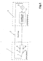
- An electronic device for fault diagnosis in an electrical system Figure 1 consists essentially of a switching device 1, which has a long two-pole supply line 2 is connected to an evaluation unit 3.
- the switching device 1 in the manner of a two-way switch can, for example, the Represent the switching output of a pressure switch that is reached when a defined Pressure in a pressure vessel changes its switching state.
- a diode 6 and 6 'attached with one connection At that alternately operated contacts 4 and 5 of the switching device 1 is a diode 6 and 6 'attached with one connection. the diodes 6 and 6 'are anti-parallel connected to each other and with their other connection with each other and with a Line of the two-pole supply line 2 connected.
- the other line of the bipolar Lead 2 is based on a switch contact 2 of the switching device 1.
- the supply line 2 is led to the evaluation unit 3.
- the evaluation unit 3 contains one Alternating signal generator 8 and a half-wave decoding circuit arrangement 9.
- the switching device 1, the alternating signal generator 8 and the half-wave decoding circuit arrangement 9 form a signal flow circuit in which the alternating signal generator 8 generated zero-symmetrical low-frequency alternating signal of approx. 660 Hz by means of the diodes 6 and 6 'arranged antiparallel in the switching device 1 depending on Switching state undergoes half-wave filtering. From the filtered and over the Lead 2 to the evaluation unit 3 retransmitted positive and negative Half-wave, the half-wave decoding circuit arrangement 9 detects the switching state - actuated or not actuated - of the switching device 1 and provides this for one Further processing available. The half-wave decoding circuit arrangement 9 also analyzes an error state of the switching device 1.
- the Half-wave decoding circuitry 9 Detects the Half-wave decoding circuitry 9 no half-wave, i. H. no Input signal, there is obviously an interruption, for example due to a line break in the long supply line 2. Receives the Half-wave decoding circuit arrangement 9 both half-waves of the low-frequency alternating signal, a short circuit can be concluded in this way.
- the Half-wave decoding circuitry 9 also provides this error condition information for further processing, for example an advertisement in a central diagnostic unit of the electrical system.
- the half-wave decoding circuit arrangement 9 essentially consists of two transmission diodes of optocouplers 10, 10 ', which are likewise connected antiparallel to one another and connected to the inputs E1 and E2, which serve as polarity filters and also the electrical isolation from the inputs E1 and Ensure E2.
- the switching transistors of the optocouplers 10 and 10 ' are each followed by an RC element 11, 11' as a low-pass filter.
- the RC element 11, 11 ' converts the pulsating DC voltage filtered by means of optocouplers 10, 10' into a largely continuous DC voltage.
- the residual ripple of the medium voltage which arises is determined by the frequency of the pulsating DC voltage and by the time constants T E and T L , it holds that T E ⁇ T L.
- the medium voltage is then converted into a unique switching signal by the Schmitt trigger 14, 14 'and transferred to the outputs A1 and A2, so that it can be further processed digitally.
- the evaluation unit 3 sends its zero-symmetrical via the integrated AC signal generator 8 Low frequency alternating signal of approx. 660 Hz via supply line 2 to the switching device 1.
- the input filter 12 includes a transient protection circuit that a sufficient immunity to interference in terms of electromagnetic compatibility (EMC) ensures.
- EMC electromagnetic compatibility
- the input filter 12 are those serving as polarity filters 13, 13 ' anti-parallel connected transmission diodes of the optocouplers 10, 10 '. This deliver a signal that is antivatent when stationary.
- FIG. 4 shows the switch-on behavior of an application circuit using a measurement record.
- FIG. 5 shows the switch-off behavior of the Schmitt trigger 14, measured at the output A1 or A2 of the Schmitt trigger 14, in the application circuit using a further measurement record.
- the limit frequency for switching the switching device 1 in the application circuit is limited to a maximum of 100 Hz.
- the switching frequency of the switching device 1 must always be below its cut-off frequency.
Landscapes
- Physics & Mathematics (AREA)
- General Physics & Mathematics (AREA)
- Arrangements For Transmission Of Measured Signals (AREA)
Applications Claiming Priority (2)
| Application Number | Priority Date | Filing Date | Title |
|---|---|---|---|
| DE1997158101 DE19758101C2 (de) | 1997-12-18 | 1997-12-18 | Elektronische Einrichtung zur Überwachung eines Schaltgerätes in einem elektrischen System |
| DE19758101 | 1997-12-18 |
Publications (1)
| Publication Number | Publication Date |
|---|---|
| EP0924528A1 true EP0924528A1 (fr) | 1999-06-23 |
Family
ID=7853517
Family Applications (1)
| Application Number | Title | Priority Date | Filing Date |
|---|---|---|---|
| EP98250435A Withdrawn EP0924528A1 (fr) | 1997-12-18 | 1998-12-10 | Dispositif électronique pour détecter la défaillance de systèmes électriques |
Country Status (2)
| Country | Link |
|---|---|
| EP (1) | EP0924528A1 (fr) |
| DE (1) | DE19758101C2 (fr) |
Cited By (4)
| Publication number | Priority date | Publication date | Assignee | Title |
|---|---|---|---|---|
| CN102520292A (zh) * | 2011-12-26 | 2012-06-27 | 广州电缆厂有限公司 | 一种多芯电缆试压转换设备 |
| CN106093758A (zh) * | 2016-05-27 | 2016-11-09 | 奇瑞汽车股份有限公司 | 一种汽车制动开关耐久试验监测设备和监测方法 |
| WO2019038122A1 (fr) * | 2017-08-21 | 2019-02-28 | Knorr-Bremse Systeme für Schienenfahrzeuge GmbH | Dispositif d'essai et procédé d'essai pour un système de freinage électropneumatique de trains |
| CN113928365A (zh) * | 2021-11-17 | 2022-01-14 | 中车南京浦镇车辆有限公司 | 一种用于轨道交通车辆可靠输出制动缓解施加状态的电路 |
Families Citing this family (5)
| Publication number | Priority date | Publication date | Assignee | Title |
|---|---|---|---|---|
| DE19947965C2 (de) * | 1999-10-05 | 2003-04-24 | Bosch Gmbh Robert | Kraftfahrzeug-Steuervorrichtung und Verfahren zum Steuern einer Kraftfahrzeug-Funktion |
| DE102004020997A1 (de) † | 2004-04-19 | 2005-11-03 | Pilz Gmbh & Co. Kg | Sicherheitsschalteinrichtung für eine Sicherheitsschaltung |
| DE102006038375A1 (de) * | 2006-08-11 | 2008-02-14 | Valeo Schalter Und Sensoren Gmbh | Schaltungsanordnung |
| DE102006054877A1 (de) * | 2006-11-20 | 2008-05-21 | Endress + Hauser Wetzer Gmbh + Co. Kg | Verfahren und Vorrichtung zur Überwachung einer Schaltereinheit |
| DE102007057990B3 (de) * | 2007-12-03 | 2009-04-16 | Knorr-Bremse Systeme für Nutzfahrzeuge GmbH | Verfahren und Schaltungsanordnung zur Überwachung von durch elektrische Impulse angesteuerten Geräten |
Citations (4)
| Publication number | Priority date | Publication date | Assignee | Title |
|---|---|---|---|---|
| GB2079958A (en) * | 1980-07-10 | 1982-01-27 | Ramage Stanley Leonard | Circuit Breaker Test Apparatus |
| US4628268A (en) * | 1982-11-18 | 1986-12-09 | Mitsubishi Denki Kabushiki Kaisha | Test device for testing an actuator circuit |
| US5506573A (en) * | 1993-05-13 | 1996-04-09 | Server Technology, Inc. | Remote sensor and method for detecting the on/off status of an automatically controlled appliance |
| US5574385A (en) * | 1994-04-28 | 1996-11-12 | Ics Triplex, Inc. | Testable solid state switch and related method |
Family Cites Families (3)
| Publication number | Priority date | Publication date | Assignee | Title |
|---|---|---|---|---|
| DE4012109C2 (de) * | 1990-04-14 | 1999-06-10 | Bosch Gmbh Robert | Vorrichtung zur Funktionsüberwachung eines elektrischen/elektronischen Schaltmittels, seines angeschlossenen Verbrauchers, einer Ansteuerung und seiner Verbindungsleitung |
| DE4443941C2 (de) * | 1994-12-09 | 1998-12-17 | Knorr Bremse Systeme | Verfahren und Vorrichtung zur Überprüfung eines Sensors |
| DE19534665C1 (de) * | 1995-09-19 | 1996-07-25 | Endress Hauser Gmbh Co | Elektronisches Schaltgerät |
-
1997
- 1997-12-18 DE DE1997158101 patent/DE19758101C2/de not_active Expired - Fee Related
-
1998
- 1998-12-10 EP EP98250435A patent/EP0924528A1/fr not_active Withdrawn
Patent Citations (4)
| Publication number | Priority date | Publication date | Assignee | Title |
|---|---|---|---|---|
| GB2079958A (en) * | 1980-07-10 | 1982-01-27 | Ramage Stanley Leonard | Circuit Breaker Test Apparatus |
| US4628268A (en) * | 1982-11-18 | 1986-12-09 | Mitsubishi Denki Kabushiki Kaisha | Test device for testing an actuator circuit |
| US5506573A (en) * | 1993-05-13 | 1996-04-09 | Server Technology, Inc. | Remote sensor and method for detecting the on/off status of an automatically controlled appliance |
| US5574385A (en) * | 1994-04-28 | 1996-11-12 | Ics Triplex, Inc. | Testable solid state switch and related method |
Cited By (7)
| Publication number | Priority date | Publication date | Assignee | Title |
|---|---|---|---|---|
| CN102520292A (zh) * | 2011-12-26 | 2012-06-27 | 广州电缆厂有限公司 | 一种多芯电缆试压转换设备 |
| CN106093758A (zh) * | 2016-05-27 | 2016-11-09 | 奇瑞汽车股份有限公司 | 一种汽车制动开关耐久试验监测设备和监测方法 |
| CN106093758B (zh) * | 2016-05-27 | 2019-03-12 | 奇瑞汽车股份有限公司 | 一种汽车制动开关耐久试验监测设备和监测方法 |
| WO2019038122A1 (fr) * | 2017-08-21 | 2019-02-28 | Knorr-Bremse Systeme für Schienenfahrzeuge GmbH | Dispositif d'essai et procédé d'essai pour un système de freinage électropneumatique de trains |
| EP3871933A1 (fr) * | 2017-08-21 | 2021-09-01 | KNORR-BREMSE Systeme für Schienenfahrzeuge GmbH | Dispositif d'essai et procédé d'essai d'un système de freinage électro-pneumatique des trains |
| CN113928365A (zh) * | 2021-11-17 | 2022-01-14 | 中车南京浦镇车辆有限公司 | 一种用于轨道交通车辆可靠输出制动缓解施加状态的电路 |
| CN113928365B (zh) * | 2021-11-17 | 2024-02-27 | 中车南京浦镇车辆有限公司 | 一种用于轨道交通车辆可靠输出制动缓解施加状态的电路 |
Also Published As
| Publication number | Publication date |
|---|---|
| DE19758101A1 (de) | 1999-07-08 |
| DE19758101C2 (de) | 2002-06-20 |
Similar Documents
| Publication | Publication Date | Title |
|---|---|---|
| EP2980659B1 (fr) | Dispositif et procédé destinés à la surveillance et la commutation d'un circuit de charge | |
| DE19653291C1 (de) | Sensor- und Auswertesystem, insbesondere für Doppelsensoren zur Endlagen- und Grenzwerterfassung | |
| EP2980660B1 (fr) | Procédé et dispositif de surveillance et de commutation d'un circuit de charge | |
| EP0546455B1 (fr) | Unité de commande électronique pour commuter plusieurs charges électriques | |
| DE19758101C2 (de) | Elektronische Einrichtung zur Überwachung eines Schaltgerätes in einem elektrischen System | |
| EP1873916A2 (fr) | Circuit de sortie sécurisé doté d'un raccordement périphérique sur un seul canal pour la sortie d'un utilisateur de bus | |
| DE3347458C2 (fr) | ||
| EP0608477B2 (fr) | Relais semi-conducteur | |
| DE10351873A1 (de) | Vorrichtung und Verfahren zum fehlersicheren Abschalten eines induktiven Verbrauchers | |
| DE19515633A1 (de) | Elektroinstallation für ein Gebäude | |
| DE102006030114B4 (de) | Sichere Eingangsschaltung mit einkanaligem Peripherieanschluss für den Eingang eines Busteilnehmers | |
| EP1917651B1 (fr) | Systeme de controle automatique de batiments ou systeme avertisseur de danger | |
| DE102016121255A1 (de) | Steuermodul für eine elektromechanische Schalteinheit, Relaismodul und Steuervorrichtung | |
| DE102010038459A1 (de) | Sicherheitssystem | |
| AT398501B (de) | Einrichtung zum signaltechnisch sicheren betrieb mehrerer elektrischer verbraucher | |
| EP0034854B1 (fr) | Circuit de surveillance pour circuit de sortie de signal d'une installation de freinage d'un véhicule | |
| DE2922782C2 (de) | Überwachungseinrichtung für zweipolige elektrische Befehlsleitungen | |
| DE19823441C1 (de) | Digitaleingabebaugruppe | |
| DE3029851A1 (de) | Schaltungsanordnung zur signaltechnisch sicheren ansteuerung eines stromverbrauchers | |
| DE102011088521B4 (de) | Erweiterungsmodul für ein Sicherheitssystem | |
| DE19808595B4 (de) | Anordnung mit einem elektrischen Verbraucher in Reihe mit zwei steuerbaren Halbleiteranordnungen | |
| DE102010011199A1 (de) | Schaltungsanordnung zur Spannungsmessung bei einem elektrischen Antrieb | |
| DE69206193T2 (de) | Steuerungsvorrichtung für Verkehrssignalanlagen. | |
| EP0656639B1 (fr) | Entrée numérique pour station de détection | |
| EP1770456A1 (fr) | Unité périphérique pour un système automatisé |
Legal Events
| Date | Code | Title | Description |
|---|---|---|---|
| PUAI | Public reference made under article 153(3) epc to a published international application that has entered the european phase |
Free format text: ORIGINAL CODE: 0009012 |
|
| AK | Designated contracting states |
Kind code of ref document: A1 Designated state(s): AT DE FR GB IT SE |
|
| AX | Request for extension of the european patent |
Free format text: AL;LT;LV;MK;RO;SI |
|
| 17P | Request for examination filed |
Effective date: 19990607 |
|
| AKX | Designation fees paid |
Free format text: AT DE FR GB IT SE |
|
| RAP1 | Party data changed (applicant data changed or rights of an application transferred) |
Owner name: KNORR-BREMSE MRP SYSTEME FUER SCHIENENFAHRZEUGE GM |
|
| STAA | Information on the status of an ep patent application or granted ep patent |
Free format text: STATUS: THE APPLICATION IS DEEMED TO BE WITHDRAWN |
|
| 18D | Application deemed to be withdrawn |
Effective date: 20030701 |