EP0924530A2 - Assemblage de bobines à gradient pour l'imagerie par résonance magnétique - Google Patents
Assemblage de bobines à gradient pour l'imagerie par résonance magnétique Download PDFInfo
- Publication number
- EP0924530A2 EP0924530A2 EP98310334A EP98310334A EP0924530A2 EP 0924530 A2 EP0924530 A2 EP 0924530A2 EP 98310334 A EP98310334 A EP 98310334A EP 98310334 A EP98310334 A EP 98310334A EP 0924530 A2 EP0924530 A2 EP 0924530A2
- Authority
- EP
- European Patent Office
- Prior art keywords
- gradient
- coil
- gradient coil
- magnetic resonance
- resonance imaging
- Prior art date
- Legal status (The legal status is an assumption and is not a legal conclusion. Google has not performed a legal analysis and makes no representation as to the accuracy of the status listed.)
- Withdrawn
Links
Images


Classifications
-
- G—PHYSICS
- G01—MEASURING; TESTING
- G01R—MEASURING ELECTRIC VARIABLES; MEASURING MAGNETIC VARIABLES
- G01R33/00—Arrangements or instruments for measuring magnetic variables
- G01R33/20—Arrangements or instruments for measuring magnetic variables involving magnetic resonance
- G01R33/28—Details of apparatus provided for in groups G01R33/44 - G01R33/64
- G01R33/38—Systems for generation, homogenisation or stabilisation of the main or gradient magnetic field
- G01R33/385—Systems for generation, homogenisation or stabilisation of the main or gradient magnetic field using gradient magnetic field coils
Definitions
- the present invention relates to magnetic resonance imaging. It finds particular application in conjunction with horizontal open magnet imaging equipment of the type used to perform interventional procedures on the torso and head of human subjects and will be described with particular reference thereto. It is to be appreciated, however, that the present invention also finds application in conjunction with imaging and interventional procedures performed on other human body parts and further, in conjunction with the imaging or analysis of non-human and inanimate subjects.
- dipoles are selectively aligned with a primary magnetic field.
- Radio frequency excitation pulses are applied to stimulate resonance in the aligned dipoles and radio frequency magnetic resonance signals are collected from the resonating dipoles.
- Gradient magnetic field pulses are applied to encode spatial position.
- smaller diameter gradient coils have been used, e.g., smaller diameter head or wrist coils.
- Typical head coils are on the order of 30 cm in diameter and wrist coils are smaller yet.
- the gradient coils substantially surround the examined region.
- a physician to gain access to the examined region, such as to perform a biopsy or other interventional procedure, the patient must be removed from within the gradient coil assembly. Moving the patient relative to the gradient coil assembly also moves the patient relative to the resultant image obtained from the coil assembly. The moved patient needs then to be re-registered with the diagnostic image before performing any interventional procedures.
- the local gradient coil is adapted for use with a stereotaxic device and includes an opening in the coil form positioned to minimize the destruction of the gradient fields and a mechanical slide bearing for moving the form with respect to the stereotaxic frame so that the opening may be limited in area and yet provide essentially unrestricted linear access to the patient.
- the windings in the neighbourhood of the opening are diverted by modifying the stream function of the windings in a manner to minimize the effect of the opening on the resultant gradient field.
- Vavrek, et al. one problem with the Vavrek, et al.
- the gradient coil layout in the Vavrek, et al. system is designed or specified using a "forward approach method," thus realizing a coil configuration having a desirable asymmetric current distribution but capable of generating only marginally acceptable levels of gradient strength and slew rate.
- the access holes are quite small and therefore provide only modest access to the patient within the coil.
- the Vavrek, et al. coil design does not allow for building both the X and Y transverse coils on the same coil carrying member radius for improved linearity.
- U.S. Patent No. 5,378,989 to Barber, et al proposes a pair of axially spaced apart cylindrical gradient coil carrying members separated by a distance defining an interventional access area.
- a patient is disposed within the bores of the coil carrying members in axial alignment therewith.
- the Barber. ct al. system is constructed such that large portions of current patterns disposed near the isocentre of the transverse coils are flared radially outward in order to permit an opening at the centre of the magnet and along the axial direction.
- Morich, et al. in their U.S. Patent No. 5,585,724 assigned to the assignee of the present invention propose yet another alternative to the prior closed gradient coil systems wherein an axially directed interstitial gap is provided between a set of coil pairs to define an interventional access area.
- a coil arrangement of the type described in the Morich, et al. patent is particularly well suited for interventional applications in open magnet systems having horizontally directed main magnetic fields.
- the gradient performance of the Morich, et al. design is somewhat limited in both gradient strength and rise time.
- a magnetic resonance imaging apparatus In accordance with the present invention, a magnetic resonance imaging apparatus is provided.
- a primary magnet assembly generates a temporally constant magnetic field through an examination region.
- a gradient coil assembly induces magnetic field gradients across the examination region.
- a radio frequency coil receives resonance signals from the examination region.
- the gradient coil carries first and second spaced apart gradient coil portions which are physically separated from each other on a coil carrying member to define at least one azimuthally directed gap extending along the coil carrying member between the first and second gradient coil portions.
- the first and second gradient coil portions are disposed in the examination region towards opposite top and bottom sides of the examination region.
- Each of the first and second gradient coil portions include internal windings for generating gradient magnetic field components along at least two mutually orthogonal axes in the examination region.
- the gradient coil assembly may be a two-part coil assembly such as a system having a hingeable/removable split top coil to facilitate easy patient receipt and exiting from the magnetic resonance imaging system. Further, the top half of the coil can be easily removed or hinged open to provide surgical access. Such access is invaluable when performing interventional MRI using an open magnet with a horizontally directed field.
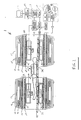
- an open or "double doughnut” type magnetic resonance imaging system 1 includes main or primary magnets 10 , 11 .
- the main or primary magnets are annual superconducting magnets disposed adjacent opposite ends of the assembly within liquid helium cans 12 , 13 .
- the liquid helium cans and the magnets are surrounded by a plurality of cold shields 14 , 15 which assist in maintaining the superconducting magnets at superconducting temperatures while minimizing helium boil off.
- the magnet assemblies are surrounded by a pair of toroidal vacuum dewars 16 , 17 .
- the magnets 10 , 11 are spaced apart to provide access to the patient.
- the helium cans, cold shields, and vacuum dewars are preferably separately closed to maintain their integrity.
- the vacuum dewars and the magnet assemblies define a pair of central bores 20 , 21 .
- a gradient coil assembly, preferably self-shielded whole body gradient coil assemblies 19 , 23 are disposed around an outer periphery of the bore 20 , 21 .
- the whole body gradient coil assemblies 19 , 23 include primary gradient coil assemblies 24 , 25 within the bore which include X, Y, and Z whole body gradient coil windings for generating magnetic field gradients along X, Y, and Z directions.
- a shield gradient coil assembly 26 , 27 is disposed within the vacuum dewar for cancelling the magnetic field gradients emanating toward the main magnetic assembly.
- a radio frequency shield 30 , 31 lines an inner surface of the gradient coil assembly.
- the radio frequency shield is transparent to gradient (kHz) range magnetic fields but is opaque to radio frequency (Mhz) signals.
- Whole body radio frequency coils 32 , 33 are disposed around the inner surface of the radio frequency shield 30 , 31 surrounding the bore 20 , 21 .
- a retractable patient support 39 supports a subject to be examined and an insertable gradient coil assembly 22 formed in accordance with the present invention.
- the patient support includes a supporting surface in a substantially horizontal plane as shown.
- the supporting surface has a longitudinal axis lengthwise along the surface and a perpendicular transverse axis across the surface, both in the horizontal plane.
- the supporting surface is slidably mounted on a patient support frame to provide a means for moving the supported surface in the horizontal plane.
- a motor drive (not shown) is mounted to the frame to drive the patient supporting surface along the frame.
- the insertable gradient coil assembly 22 includes a lower portion 44 which is mounted to the patient support 39 .
- An upper, selectively removable portion 46 is electrically and mechanically interconnected with the lower portion 44 for imaging and is released and removed to facilitate patient access.
- the upper and lower gradient coil assemblies 46 , 44 are constructed on a rigid dielectric former.
- the upper and lower assemblies together carry a pair of X-gradient coil assemblies as illustrated in FIGURES 4 and 7 according to a first preferred embodiment and a pair of Y-gradient coil assemblies also as illustrated in FIGURES 4 and 7 according to a first preferred embodiment.
- the X and Y-gradient coils are arranged on the formers substantially as shown in FIGURES 3 and 6.
- Z-gradient coils in the form of annular loops are also carried by the dielectric formers preferably in a manner as shown in FIGURE 5.
- the X and Y-gradient coils are constructed of copper foil laminated to the dielectric former. Electrical connectors, such as metal pins and sockets, are mounted in the upper and lower former portions for providing electrical continuity between coil portions on the upper and lower coil portions when the coil portions are assembled together.
- a sequence control 71 In operation, a sequence control 71 generates the appropriate gradient and radio frequency pulses of a selected magnetic resonance imaging sequence. More specifically, the characteristics of a selected magnetic resonance imaging sequence are withdrawn from a sequence memory 73 and stored and used to control a radio frequency sequence controller 75 and a gradient pulse controller 77 .
- a common clock 79 clocks the radio frequency and gradient controllers simultaneously.
- the selected radio frequency pulse signals are conveyed to a radio frequency transmitter 81 which is selectively connectable to the whole body radio frequency coil 33 and to an insertable radio frequency coil.
- the insertable radio frequency coil or a surface coil receives the magnetic resonance signal and conveys it to a digital receiver 83 .
- the digital receiver 83 demodulates and digitizes the magnetic resonance signal.
- a reconstruction processor 85 reconstructs the received magnetic resonance signals into a volumetric or slice image representation.
- a volume image memory 87 stores one or a series of image representations from the reconstruction processor.
- a video processor 89 converts the selected portions of the image representation in the image memory 87 into appropriate format for display on a monitor 91 . For example, the video processor may convert selected slices of an imaged volume into appropriate format for display.
- the video processor can select the corresponding slice in a series or temporally displaced images of the heart to provide a cine image representation which simulates a motion picture of the selected slice of the heart as the heart is beating.
- the video processor can assemble a three-dimensional rendering of a selected organ or region.
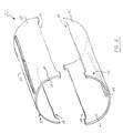
- the insertable gradient coil assembly 22 includes a bottom half gradient coil portion 44 and a top half gradient coil portion 46 as described generally above.
- the top and bottom half portions are substantially separated by a pair of left and right axially extending elongate access apertures 48 , 50 .
- the left and right access apertures are preferably circumferentially spaced apart by about 180° on the cylindrical coil assembly 22 as shown.
- Each of the top and bottom half portions 46 , 44 are additionally respectively substantially bisected by a top axially extending elongate aperture 52 and a bottom axially extending elongate access aperture 54 .
- the top and bottom access apertures are also preferably circumferentially spaced apart by about 180° on the cylindrical coil assembly 22 as shown.
- the top access aperture 52 divides the top half gradient coil portion 46 into a top left coil portion 56 and a mirror image top right coil portion 58 .
- the bottom access aperture 54 divides the bottom half gradient coil portion 44 into a bottom left coil portion 60 and a mirror image bottom right coil portion 62 .
- the apertures are formed by a set of azimuthal gaps defining a set of elongate circumferentially spaced apart ports extending along the entire length of the coil assembly to provide an interventionist access to a patient received within the closed coil assembly.
- the top half portion 46 is electrically and mechanically interconnected with the bottom half portion 44 for imaging and is released and removed to facilitate patient entry and exit from the coil assembly.
- the bottom and top half gradient coil portions 44 , 46 are constructed on a rigid dielectric former.
- each of the bottom and top half gradient coil portions 44 , 46 carry four X-gradient coil members and four Y-gradient coil members, respectively.
- the gradient coil members are constructed from copper sheets which are either machined or etched into the desired patterns as shown.
- the sheets are preferably bonded to an FR-4 backing material and are arranged on the bottom and top half gradient coil portions substantially as shown in the FIGURE.
- the top half gradient coil portion 46 carries four discrete X-gradient coil members 80-83 generally as shown.
- the bottom half gradient coil portion 44 carries a corresponding set of X-gradient coil members 84-87 in a mirror image substantially as shown.
- the preferred bunched coil patterns for the first set of X-gradient coil members 80-83 carried on the top half gradient coil portion 46 are shown in FIGURE 4.
- the other X-gradient coil members 84-87 disposed on the bottom half gradient coil portion 44 are preferably constructed substantially as shown in FIGURE 4 as well.
- the top half gradient coil portion 46 carries four discrete Y-gradient coil members 90-93 generally as shown.
- the bottom half gradient coil portion 44 carries a corresponding set of Y-gradient coil members 94-97 in a mirror image substantially as shown.
- the Y-gradient coil members 90-97 are stacked onto the X-gradient coil members 80-87 .
- the X-gradient coil members may be stacked on the Y-gradient coil members or, as yet another alternative, the stacking arrangement between the X and Y-gradient coil members may be randomly or evenly distributed over the insertable gradient coil assembly 22 .
- the Z-axis coil 100 includes a top set of Z-axis coil members 102 and a corresponding mirror image bottom set of Z-axis coil members 104 . Electric current flowing through the top and bottom set of Z-axis coil members 102 , 104 cooperate to generate the Z-axis gradient field in a well known manner.
- the Z-axis coil is constructed from copper sheets which are either machined or etched into the desired pattern shown. The machined or etched copper sheets are then bonded to an FR-4 backing material and are then rolled or bent into the desired shape shown in FIGURE 5.
- the Z-axis pattern could also be constructed by abrasive water jet cutting or by wire winding or the like.
- FIGURE 5 illustrates a single reversal in the Z-axis windings occurring at the isocentre of the coil, other designs could be easily accommodated.
- the returns are routed along left and right flanges 106 , 108 as shown so that the field from the top and bottom sets 102 , 104 cancel.
- each half of the Z-axis coil will separately generate a net torque, this torque is constrained in the preferred embodiment by alignment pins and latching mechanisms located in the flanges of the gradient coil formers described below in greater detail with reference to FIGURES 8 and 9.
- each of the bottom and top half gradient coil portions 44 , 46 carry four X-gradient coil members and four Y-gradient coil members, respectively.
- both the X and Y-gradient coil members are radially co-located on the gradient coil former in a manner substantially as shown. That is, the coils are constructed to fit upon the same radius.
- One advantage is an increase in the available patient aperture space.
- the radial co-location of the X and Y transverse gradient coil members allows for a decrease in size of the overall gradient coil assembly structure since only a single set of gradient coils need to be constructed rather than two overlapping sets as was traditionally required.
- the top half coil portion 46 carries four discrete X-gradient coil members 80'-83' and four discrete Y-gradient coil members 90'-93' generally as shown.
- the bottom half gradient coil portion 44 carries a corresponding set of X-gradient coil members 84'-87' and a set of Y-gradient coil members 94'-97' in a mirror image substantially as shown.
- the coil members are preferably constructed from machined or etched copper sheets and then bonded together substantially as described above.
- the X and Y-gradient coil members are symmetrically spaced apart and disposed over the gradient coil assembly 22 for the purpose of minimizing the effects of net torque on the coil structures. As shown, the coil members experience no net torque effects. This significantly reduces the coil vibration which is normally present in coil structures having non-symmetric current patterns. As a result, the medical image acquired in the magnetic resonance imaging system 10 has only minimum distortion and minimum ghosting effects.
- the required stored magnetic energy of the present invention is substantially lower than the required stored magnetic energy in prior art systems.
- the octapole gradient coil with azimuthal gap of arbitrary width in accordance with the present invention has double the slew rate on 30% reduced length as compared against the prior art coil assembly of Morich, et al.
- the gradient coil arrangements according to the present invention generate six times the gradient strength and two hundred times the slew rate of the Vavrek, et al. open gradient coil system described generally above.
- the bottom half gradient coil portion 44 is adapted for connection to the patient supporting surface 36 as described above and further includes a pair of left and right connection flanges 110, 112 .
- the left and right connection flanges are adapted to slidingly engage and interlock with a corresponding set of left and right connection flanges 114 , 116 formed on the top half gradient coil portion 46 .
- the left and right connection flanges 114 , 116 are adapted to lock onto the bottom left and right connection flanges using any suitable mechanical connecting means such as the hook members 118 , 120 as shown.
- the hook members extend vertically past the left and right connection flanges 110 , 112 and engage the back sides thereof in a manner substantially as shown.
- alternative sliding connection arrangements are possible as would be understood by those skilled in the art.
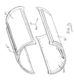
- FIGURE 9 an alternative split top octapole gradient coil connecting system is shown including a pair of left and right connection hinges 122 , 124 which are adapted to connect the bottom and top half gradient coil portions 44, 46 in a manner substantially as shown.
- the bottom half gradient coil portion 44 is connected preferably to the patient supporting surface 36 .
- the left and right hinges enable the top half gradient coil portion 46 to open in a manner as shown to permit easy patient entrance and removal from the gradient coil assembly 22 .
- connection flanges 110-113 are provided on the connection flanges 110-113 in a manner to electrically connect the gradient coil members disposed on the top half gradient coil portion 46 to those disposed on the bottom half gradient coil portion 44 .
- the electrical connection elements are electric contact strips for slidable mechanical and electrical engagement between the corresponding opposed contact members.
- the electrical contact elements are preferably pin and socket members which are adapted for intermateable connection when the top half gradient coil portion 46 is hinged into a closed position with the bottom half gradient coil portion 44 .
- the novel preferred method of generating a discrete transverse current density with coils arranged to define an azimuthal gap of arbitrary width will next be described.
- the technique is based in part on the so-called Turner energy minimization approach.
- an analytical expression for the azimuthal component of the current density, J a / ⁇ is found that both satisfies all the predetermined symmetry conditions which are in accord with the symmetry behaviour of traditional transverse gradient coil geometry, and vanishes on any predetermined azimuthal ( ⁇ ') location.
- the current density J a / ⁇ is symmetric along the z direction.
- the expression for the axial component of the current density is: where a is the radius of the coil in the expression. Both currents are zero for
- I m (kp)K' m (ka) are the modified Bessel functions of the first and second order
- S mab 1 - I'm ( ka ) K'm ( kb ) I'm ( kb ) K'm ( ka ) when shielding coil with radius b is present.
- S mab when only a primary coil is present.
- the expression for the magnetic energy stored in the coil is:
- the expression of the magnetic energy stored in the coil is:
- the functional ⁇ in terms of the stored magnetic energy and the magnetic field is constructed as: where N represents the total number of constraint points in the expression and B zSC ( r j ) is the value of the gradient field at the constrain point r j .
- N represents the total number of constraint points in the expression
- B zSC ( r j ) is the value of the gradient field at the constrain point r j .
- J a is a 1 x M matrix
- C is a M x M matrix
- ⁇ is a 1 x N matrix
- D is a N x M matrix in the expression.
- the Lagrange multipliers are found using the expression of the magnetic field.
- the matrix representation of the magnetic field thus becomes: where B z is a 1 x N matrix in the expression and the superscript t is the symbol for the transpose matrix.
- the expression for the Fourier components of the current for the gradient coil are solved in the straightforward manner described above.
- the continuous distribution of the current density for the coil is generated by substituting the Fourier components of the current back into the expression of the current density J a / ⁇ .
- FIGURES 10 and 11 With reference next to FIGURES 10 and 11, the design of an analytical model construction of an Octapole X-gradient coil with the azimuthal gap according to the present invention will be described.
- the model assumes a cylindrical radius of 191.3 mm and a total length of 60 cm.
- Three constraint points were next selected to specify the quality of the gradient field inside a 23 cm DSV.
- the first constraint point sets the strength of gradient field to 24.5 mT/m
- the second limits the variation of the gradient field along its gradient axis (X) to be within 15% from its ideal value at distance of 0.115m from the geometric centre of the coil
- the third constraint defines a 14% gradient field uniformity inside the 23 cm DSV.
- n P i Z i B zsc ( n ) 1 0.0010 0.000 0.000024530 2 0.1150 0.0000 0.003127600 3 0.0010 0.1150 0.00002085050
- the continuous current distribution for the X-gradient coil are generated. Applying the stream function technique, the discrete current pattern is obtained as shown in FIGURE 11. The common value of the current for the 12 discrete loops is 199.53 Amps.
- the discrete coil pattern is used to calculate the magnetic field via the Biot-Savart law.
- the discretization mechanism is appropriate and the choice of the number of discrete loops is adequate to generate the desired quality of the magnetic field.
- the gradient field of the discrete coil pattern is very linear along its primary gradient axis (X).
- the net gradient field strength at the origin is 24.53 mT/m which is a 0.1% deviation from its constrained value.
- the linearity of the coil inside the 23 cm DSV is 17.89%.
- FIGURE 11 shows the level of uniformity of the gradient field inside the 23 cm DSV. Specifically, for the 12 discrete loop configuration example described here, the overall uniformity of the gradient inside the 23 cm DSV is 14%.
- TABLE 2 illustrates all the properties of the octapole X-gradient coil as well as a comparison against a X-gradient coil with interstitial gap that has the same gradient strength. Comparing both gradients, it is clear that for an input current/voltage of 300A/400V, the slew rate of the octapole gradient coil with the azimuthal gap according to the present invention is twice as fast as the slew rate of a typical prior art X-gradient coil with the interstitial gap.
- a physical prototype X-gradient coil was constructed by applying a 12 AWG insulated wire onto a fibreglass cylindrical tube. The coil interconnects were placed on the tube in a manner that they would not interfere with the azimuthal gap. The measured inductance of the prototype coil was 158 ⁇ H at 1 kHz, which represents only a 2.5% deviation from the theoretical value.
- the gradient field is plotted along its primary X-gradient axis as shown in FIGURE 14.
- TABLE 3 below shows a comparison of the gradient field (mT/m/A) between the numerical and the experimental results at various points along the major X-gradient coil axis.
- the "C" magnet type magnetic imaging system 10' includes a magnetomotive force means A in the form of a pair of resistive magnet drivers 12' , 14' disposed adjacent pole pieces 16' , 18' on opposite ends of a C-shaped ferromagnetic flux path B .
- the magnetomotive force means A together with a magnetic flux stabilizing means C creates and stabilizes a magnetic field across an air gap 20' between the pole faces and along the ferromagnetic flux path B .
- a retractable patient support D selectively supports a patient or subject to be examined, together with an insertable gradient coil 22' in accordance with the present invention in the air gap 20' defined between the pole faces.
- An energizing and calibration system E is used to set up the magnetic field across the air gap 20' .
- Magnetic resonance electronics F selectively induce magnetic resonance of dipoles in the image region and process resultant received magnetic resonance signals to create an image or other diagnostic information.
- the ferromagnetic flux path B includes a C-shaped ferromagnetic member 24' having a first end 26' , a second end 28' , and a middle portion 30' .
- the first pole piece 16' on the first end 26' of the flux path together with the second pole piece 18' on the second end 28' define the air gap 20' therebetween.
- the C-shaped member 24' is configured to minimize the length of the ferromagnetic flux path while spacing the ferromagnetic flux path sufficiently from the gap to minimize distortion to the magnetic field in the air gap.
- the magnetic flux stabilizing means C includes a superconducting cryodriver 32' which encircles a segment of the middle portion 30' of the C-shaped ferromagnetic member 24' .
- the cryodriver 32' includes a cryostat 34' which houses an annular superconductor magnet that encircles the flux path.
- the patient support D includes a patient supporting surface 36' in a substantially horizontal plane.
- the supporting surface has a longitudinal axis lengthwise along the surface and a perpendicular transverse axis across the surface, both in the horizontal plane.
- An elevation adjusting means 38' selectively adjusts the relative height of the supporting surface.
- the supporting surface is slidably mounted on a support frame 40' to provide a means for moving the supporting surface in the horizontal plane.
- a motor drive 42' is mounted to the frame to drive the patient supporting surface along the frame.
- the electronics section F includes a radio frequency transmitter means 60' which selectively applies radio frequency pulses to a radio frequency coil (not shown) to excite magnetic resonance of dipoles in the gap magnetic field.
- a receiver 62' receives magnetic resonance signals from the region of interest using a radio frequency coil (not shown) as an antenna.
- a gradient coil control 64' applies electrical pulses to a gradient field coil (not shown) to cause gradients across the gap magnetic field to encode the magnetic resonance signals.
- An image reconstruction processor 66' performs an inverse two-dimensional Fourier transfer or other known algorithm to reconstruct an image representation from the received magnetic resonance signals. The image representations are stored in a memory 68' , displayed on a video monitor 70' , further processed, communicated to another apparatus, or the like.
- a central magnetic resonance controller 72' controls the excitation power control 74' to the resistive drivers 12' , 14' , the RF transmitter 60' , and the gradient field control 64' to implement a preselected magnetic resonance imaging sequence as is conventional in the art.
- the insertable gradient coil 22' is preferably formed of a bottom half gradient coil portion 44' fixedly attached to the supporting surface and a top half gradient coil portion 46' removable from the bottom half to facilitate patient receipt and exiting from the magnetic resonance imaging system 10' .
- a pair of left and right elongate apertures 48' , 50' extend axially along the length of the insertable gradient coil 22' generally as shown to provide access to a patient received within the closed gradient coil assembly during interventional procedures or the like.
- a pair of top and bottom elongate apertures 52' , 54' are formed in the insertable gradient coil 22' generally as shown in accordance with the present invention to further facilitate access to the patient or specimen during interventional procedures in the magnetic resonance imaging system 10' .
- the left and right apertures 48' , 50' are formed on the separation or parting line between the top and bottom half gradient coil portions 46' , 44' .
- the apertures can be disposed in any circumferentially spaced apart manner on the gradient coil 22' .
- the top and bottom half gradient coil portions 46' , 44' together carry a set X-gradient coil assemblies as illustrated in FIGURES 13 and 14 and a set of Y-gradient coil assemblies as illustrated in FIGURES 15 and 16.
- the X and Y-gradient coils are arranged on the formers of the insertable gradient coil assembly substantially as shown in FIGURES 14 and 16.
- the Z-gradient coil is in the form of annular loops carried by the dielectric formers substantially in the manner as shown above in connection with FIGURE 5.
- the X and Y-gradient coils are constructed of copper foil laminated to the dielectric former. Electrical connectors such as metal pins and sockets, are mounted in the upper and lower former portions as described above, for providing electrical continuity between coil portions on the upper and lower coil portions when the coil members are assembled together.
- each of the top and bottom half gradient coil portions 46' , 44' carry four X-gradient coil members and two Y-gradient coil members, respectively.
- the Y-gradient coils are configured substantially as shown in FIGURE 13 and are arranged on the former member as shown in FIGURE 14.
- FIGURE 13 illustrates a pair of Y-gradient coils. Two pairs of Y-gradient coils are carried on each of the top and bottom coil portions 46' , 44' .
- the X-gradient coils in the alternative preferred embodiment for use in vertically directed main magnetic fields is shown in FIGURE 15.
- the X-gradient coils are disposed on the former member substantially as shown in FIGURE 16.
- each of the top and bottom half gradient coil portions 46' , 44' carry a pair of X-gradient coil members as shown.
- One advantage of the octapole magnetic resonance gradient coil system with elongate azimuthal gap is an improvement in gradient field strength and slew rate whereby the resolution of the imaged subject is greatly improved. Another advantage resides in improved imaging speeds and reduced data acquisition times. Another advantage is that it facilitates access to the examined region of the patient, while the patient is disposed in a known relationship to the gradient magnetic field coils. Yet another advantage is the construction of a gradient magnetic field coil assembly in a snap together shell arrangement whereby the top shell is removable from the bottom shell to facilitate patient receipt and exiting from the magnetic resonance imaging apparatus. Still yet another advantage is an improvement in the linearity of the gradient magnetic field coil assembly due to the transverse coils being disposed at equal radius distances on the coil carrying assembly.
Landscapes
- Physics & Mathematics (AREA)
- Condensed Matter Physics & Semiconductors (AREA)
- General Physics & Mathematics (AREA)
- Magnetic Resonance Imaging Apparatus (AREA)
Applications Claiming Priority (2)
| Application Number | Priority Date | Filing Date | Title |
|---|---|---|---|
| US996435 | 1997-12-22 | ||
| US08/996,435 US5952830A (en) | 1997-12-22 | 1997-12-22 | Octapole magnetic resonance gradient coil system with elongate azimuthal gap |
Publications (2)
| Publication Number | Publication Date |
|---|---|
| EP0924530A2 true EP0924530A2 (fr) | 1999-06-23 |
| EP0924530A3 EP0924530A3 (fr) | 2001-04-11 |
Family
ID=25542914
Family Applications (1)
| Application Number | Title | Priority Date | Filing Date |
|---|---|---|---|
| EP98310334A Withdrawn EP0924530A3 (fr) | 1997-12-22 | 1998-12-16 | Assemblage de bobines à gradient pour l'imagerie par résonance magnétique |
Country Status (3)
| Country | Link |
|---|---|
| US (1) | US5952830A (fr) |
| EP (1) | EP0924530A3 (fr) |
| JP (1) | JP2000107153A (fr) |
Cited By (13)
| Publication number | Priority date | Publication date | Assignee | Title |
|---|---|---|---|---|
| GB2401946A (en) * | 2003-03-25 | 2004-11-24 | Siemens Ag | Gradient and rf coils for MRI apparatus |
| WO2004111670A1 (fr) * | 2003-06-13 | 2004-12-23 | Koninklijke Philips Electronics N.V. | Systeme de connexion pour bobines rf a partie superieure detachee |
| EP2163912A3 (fr) * | 2008-09-11 | 2010-11-24 | Allegheny-Singer Research Institute | IRM hybride |
| US7999544B2 (en) | 2007-04-11 | 2011-08-16 | Allegheny-Singer Research Institute | Rapid MRI dynamic imaging using mach |
| US8131046B2 (en) | 2008-10-29 | 2012-03-06 | Allegheny-Singer Research Institute | Magnetic resonance imager using cylindrical offset region of excitation, and method |
| US8198892B2 (en) | 2009-04-22 | 2012-06-12 | Allegheny-Singer Research Institute | Steady-state-free-precession (SSFP) magnetic resonance imaging (MRI) and method |
| US8219176B2 (en) | 2007-03-08 | 2012-07-10 | Allegheny-Singer Research Institute | Single coil parallel imaging |
| US8339138B2 (en) | 2008-10-15 | 2012-12-25 | University Of Utah Research Foundation | Dynamic composite gradient systems for MRI |
| US8405394B2 (en) | 2009-10-20 | 2013-03-26 | Allegheny-Singer Research Institute | Targeted acquisition using holistic ordering (TACHO) approach for high signal to noise imaging |
| US8688193B2 (en) | 2008-06-26 | 2014-04-01 | Allegheny-Singer Research Institute | Magnetic resonance imager, method and program which continuously applies steady-state free precession to k-space |
| CN103713268A (zh) * | 2012-09-29 | 2014-04-09 | 上海联影医疗科技有限公司 | 一种具有辅助匀场线圈的磁共振系统及匀场方法 |
| EP3047292A4 (fr) * | 2013-09-17 | 2017-03-15 | Synaptive Medical (Barbados) Inc. | Ensemble bobine pour l'imagerie par résonance magnétique |
| CN111352053A (zh) * | 2018-12-20 | 2020-06-30 | 西门子医疗有限公司 | 用于超导磁体的低温恒温器 |
Families Citing this family (40)
| Publication number | Priority date | Publication date | Assignee | Title |
|---|---|---|---|---|
| JP3702106B2 (ja) * | 1998-09-29 | 2005-10-05 | 株式会社東芝 | 磁気共鳴イメージング装置 |
| US6278275B1 (en) | 1999-10-18 | 2001-08-21 | Picker International, Inc. | Gradient coil set with non-zero first gradient field vector derivative |
| US6278276B1 (en) | 1999-11-16 | 2001-08-21 | Picker International, Inc. | Phased array gradient coil set with an off center gradient field sweet spot |
| US6262576B1 (en) | 1999-11-16 | 2001-07-17 | Picker International, Inc. | Phased array planar gradient coil set for MRI systems |
| DE10016229B4 (de) * | 2000-03-31 | 2005-12-22 | Siemens Ag | Polarisierende Antenne für ein Magnetresonanzgerät |
| US6522144B2 (en) * | 2000-12-22 | 2003-02-18 | Ge Medical Systems Global Technology Company, Llc | RF shielding method and apparatus for an open MRI system |
| DE10109543B4 (de) * | 2001-02-28 | 2006-03-30 | Siemens Ag | Verfahren zum Betrieb eines Gradientenspulensystems eines Magnetresonanzgeräts |
| US6538443B2 (en) * | 2001-03-20 | 2003-03-25 | Koninklijke Philips Electronics N.V. | MRI gradient coil with variable field of view and apparatus and methods employing the same |
| DE10120284C1 (de) * | 2001-04-25 | 2003-01-02 | Siemens Ag | Gradientenspulensystem und Magnetresonanzgerät mit dem Gradientenspulensystem |
| DE50210790D1 (de) * | 2001-05-30 | 2007-10-11 | Siemens Ag | Magnetresonanzgerät mit einer verfahrbaren Gradientenspuleneinheit |
| DE10229489B4 (de) * | 2002-07-01 | 2008-04-30 | Siemens Ag | Vorrichtung zum Einbringen einer Gradientenspuleneinheit |
| DE10335789B4 (de) * | 2003-08-05 | 2007-01-04 | Siemens Ag | Magnetresonanzgerät mit einer Höhlung und mit einem in der Höhlung angeordneten Gradientenspulensystem |
| WO2005047915A1 (fr) * | 2003-11-12 | 2005-05-26 | Koninklijke Philips Electronics N.V. | Systeme d'i.r.m. a bobines de reception rf fixees au boitier |
| US7400147B2 (en) * | 2005-11-03 | 2008-07-15 | Uri Rapoport | Self-fastening cage surrounding a magnetic resonance device and methods thereof |
| DE102006000925B4 (de) * | 2006-01-05 | 2007-10-25 | Siemens Ag | Vorrichtung zur Montage einer zylindrischen Gradientenspule in einem zylindrischen Magneten einer Magnetresonanzanlage |
| DE102006005285A1 (de) * | 2006-02-06 | 2007-08-16 | Siemens Ag | Magnetresonanzeinrichtung sowie Verfahren zur Überwachung einer Magnetresonanzeinrichtung |
| DE102006045427A1 (de) * | 2006-09-26 | 2008-04-10 | Siemens Ag | Detektionseinheit zur Anordnung in einer Felderzeugungseinheit eines MR-Geräts |
| DE102006046044B4 (de) * | 2006-09-28 | 2010-04-08 | Siemens Ag | Hochfrequenzsendeanordnung einer Magnetresonanzanlage |
| BRPI0809689B1 (pt) | 2007-04-04 | 2019-03-19 | Koninklijke Philips N.V. | Bobina de gradiente de campo magnético, escâner por ressonância magnética, e, escâner híbrido |
| DE102007059521B4 (de) * | 2007-12-11 | 2016-11-17 | Siemens Healthcare Gmbh | Hochstrom-Koaxialverbindung mit zwei miteinander verbindbaren Steckelementen sowie Gradientenspule mit angeschlossener Hochstrom-Koaxialleitung |
| DE102008025677B4 (de) | 2008-05-29 | 2012-09-27 | Siemens Aktiengesellschaft | Magnetresonanzgerät mit einer PET-Einheit |
| DE102008063629B4 (de) * | 2008-12-18 | 2012-05-24 | Siemens Aktiengesellschaft | Lokalspulenanordnung für Magnetresonanzanwendungen und Patientenliege für eine Magnetresonanzanlage mit integrierten elektrischen Schnittstellen |
| AU2010273298B2 (en) | 2009-07-15 | 2014-10-23 | Viewray Technologies, Inc. | Method and apparatus for shielding a linear accelerator and a magnetic resonance imaging device from each other |
| JP5732065B2 (ja) | 2009-11-20 | 2015-06-10 | ビューレイ・インコーポレイテッドViewRay Incorporated | 自己遮蔽型傾斜コイル |
| EP2388610A1 (fr) * | 2010-05-20 | 2011-11-23 | Koninklijke Philips Electronics N.V. | Bobine de gradient imagerie à résonance magnétique, ensemble d'aimant et système |
| DE102011075454B4 (de) * | 2011-05-06 | 2016-07-21 | Siemens Healthcare Gmbh | Größenverstellbare Kopf-Hals-MR-Oberflächenspule mit klappbarem Oberteil |
| US8981779B2 (en) | 2011-12-13 | 2015-03-17 | Viewray Incorporated | Active resistive shimming fro MRI devices |
| DE102012201370B4 (de) * | 2012-01-31 | 2016-02-11 | Siemens Aktiengesellschaft | Halterung für Double-Loop-Coil (Doppel-Schleifen-Spule) für z.B. MCP-Aufnahmen |
| CN104411237B (zh) * | 2012-06-27 | 2017-05-10 | 株式会社日立制作所 | 倾斜磁场线圈装置及磁共振成像装置 |
| DE102012213594B4 (de) * | 2012-08-01 | 2016-07-28 | Siemens Healthcare Gmbh | MR- Oberflächenspule mit integrierter automatischer Patientenfixierung |
| US9889318B2 (en) | 2012-10-26 | 2018-02-13 | Viewray Technologies, Inc. | Assessment and improvement of treatment using imaging of physiological responses to radiation therapy |
| US9446263B2 (en) | 2013-03-15 | 2016-09-20 | Viewray Technologies, Inc. | Systems and methods for linear accelerator radiotherapy with magnetic resonance imaging |
| CN103202695B (zh) * | 2013-03-20 | 2015-02-18 | 江苏麦格思频仪器有限公司 | 核磁共振成像系统及其方法 |
| US20160069967A1 (en) * | 2014-09-10 | 2016-03-10 | General Electric Company | Apparatus and system for imaging an intubated patient |
| US10228336B2 (en) * | 2015-09-01 | 2019-03-12 | Chevron U.S.A. Inc. | Mobile NMR sensor for analyzing subsurface samples |
| EP3423153B1 (fr) | 2016-03-02 | 2021-05-19 | ViewRay Technologies, Inc. | Thérapie par particules à imagerie par résonance magnétique |
| JP7127126B2 (ja) | 2017-12-06 | 2022-08-29 | ビューレイ・テクノロジーズ・インコーポレイテッド | 放射線治療のシステム、方法およびソフトウェア |
| US11209509B2 (en) | 2018-05-16 | 2021-12-28 | Viewray Technologies, Inc. | Resistive electromagnet systems and methods |
| TW202015621A (zh) | 2018-07-19 | 2020-05-01 | 美商超精細研究股份有限公司 | 在磁共振成像中患者定位之方法及設備 |
| WO2020198395A1 (fr) * | 2019-03-25 | 2020-10-01 | Promaxo, Inc. | Bobines de champ-gradient d'irm rapide monoface et leurs applications |
Family Cites Families (8)
| Publication number | Priority date | Publication date | Assignee | Title |
|---|---|---|---|---|
| US5304933A (en) * | 1991-08-01 | 1994-04-19 | General Electric Company | Surgical local gradient coil |
| US5378989A (en) * | 1993-11-02 | 1995-01-03 | General Electric Company | Open gradient coils for magnetic resonance imaging |
| GB2295020B (en) * | 1994-11-03 | 1999-05-19 | Elscint Ltd | Modular whole - body gradient coil |
| DE19504171C2 (de) * | 1995-02-07 | 1998-04-30 | Siemens Ag | Trennbare, lokale Gradientenspulenanordnung für Kernspintomographiegeräte |
| US5585724A (en) * | 1995-06-12 | 1996-12-17 | Picker International, Inc. | Magnetic resonance gradient coils with interstitial gap |
| US5729141A (en) * | 1996-03-19 | 1998-03-17 | Intermagnetics General Corporation | Split gradient coils for MRI system |
| US5675305A (en) * | 1996-07-17 | 1997-10-07 | Picker International, Inc. | Multiple driven C magnet |
| US5804968A (en) * | 1997-01-29 | 1998-09-08 | Picker International, Inc. | Gradient coils with reduced eddy currents |
-
1997
- 1997-12-22 US US08/996,435 patent/US5952830A/en not_active Expired - Fee Related
-
1998
- 1998-12-16 EP EP98310334A patent/EP0924530A3/fr not_active Withdrawn
- 1998-12-22 JP JP10378254A patent/JP2000107153A/ja active Pending
Cited By (21)
| Publication number | Priority date | Publication date | Assignee | Title |
|---|---|---|---|---|
| GB2401946A (en) * | 2003-03-25 | 2004-11-24 | Siemens Ag | Gradient and rf coils for MRI apparatus |
| US6930482B2 (en) | 2003-03-25 | 2005-08-16 | Siemens Aktiengesellschaft | Time-variable magnetic fields generator for a magnetic resonance apparatus |
| GB2401946B (en) * | 2003-03-25 | 2006-10-04 | Siemens Ag | Generator for time-variable magnetic fields of a magnetic resonance instrument and magnetic resonance instrument with the generator |
| WO2004111670A1 (fr) * | 2003-06-13 | 2004-12-23 | Koninklijke Philips Electronics N.V. | Systeme de connexion pour bobines rf a partie superieure detachee |
| US7288938B2 (en) | 2003-06-13 | 2007-10-30 | Koninklijke Philips Electronics N.V. | Connection system for split-top RF coils |
| CN100516922C (zh) * | 2003-06-13 | 2009-07-22 | 皇家飞利浦电子股份有限公司 | 用于磁共振成像的顶部拼合射频线圈及磁共振成像设备 |
| US8219176B2 (en) | 2007-03-08 | 2012-07-10 | Allegheny-Singer Research Institute | Single coil parallel imaging |
| US7999544B2 (en) | 2007-04-11 | 2011-08-16 | Allegheny-Singer Research Institute | Rapid MRI dynamic imaging using mach |
| US8688193B2 (en) | 2008-06-26 | 2014-04-01 | Allegheny-Singer Research Institute | Magnetic resonance imager, method and program which continuously applies steady-state free precession to k-space |
| EP2163912A3 (fr) * | 2008-09-11 | 2010-11-24 | Allegheny-Singer Research Institute | IRM hybride |
| US8339138B2 (en) | 2008-10-15 | 2012-12-25 | University Of Utah Research Foundation | Dynamic composite gradient systems for MRI |
| US8131046B2 (en) | 2008-10-29 | 2012-03-06 | Allegheny-Singer Research Institute | Magnetic resonance imager using cylindrical offset region of excitation, and method |
| US8198892B2 (en) | 2009-04-22 | 2012-06-12 | Allegheny-Singer Research Institute | Steady-state-free-precession (SSFP) magnetic resonance imaging (MRI) and method |
| US8405394B2 (en) | 2009-10-20 | 2013-03-26 | Allegheny-Singer Research Institute | Targeted acquisition using holistic ordering (TACHO) approach for high signal to noise imaging |
| CN103713268A (zh) * | 2012-09-29 | 2014-04-09 | 上海联影医疗科技有限公司 | 一种具有辅助匀场线圈的磁共振系统及匀场方法 |
| CN103713268B (zh) * | 2012-09-29 | 2016-05-18 | 上海联影医疗科技有限公司 | 一种具有辅助匀场线圈的磁共振系统及匀场方法 |
| EP3047292A4 (fr) * | 2013-09-17 | 2017-03-15 | Synaptive Medical (Barbados) Inc. | Ensemble bobine pour l'imagerie par résonance magnétique |
| CN111352053A (zh) * | 2018-12-20 | 2020-06-30 | 西门子医疗有限公司 | 用于超导磁体的低温恒温器 |
| GB2580047A (en) * | 2018-12-20 | 2020-07-15 | Siemens Healthcare Ltd | Cryostat for superconductive magnet |
| GB2580047B (en) * | 2018-12-20 | 2021-02-24 | Siemens Healthcare Ltd | Cryostat for superconductive magnet |
| US11714148B2 (en) | 2018-12-20 | 2023-08-01 | Siemens Healthcare Limited | Cryostat for superconductive magnet |
Also Published As
| Publication number | Publication date |
|---|---|
| EP0924530A3 (fr) | 2001-04-11 |
| JP2000107153A (ja) | 2000-04-18 |
| US5952830A (en) | 1999-09-14 |
Similar Documents
| Publication | Publication Date | Title |
|---|---|---|
| US5952830A (en) | Octapole magnetic resonance gradient coil system with elongate azimuthal gap | |
| EP0749018B1 (fr) | Un système d'imagerie par résonance magnétique | |
| EP0404461B1 (fr) | Assemblage de bobines à gradient pour générer les gradients d'un champ magnétique à travers un domaine | |
| US5280248A (en) | Biplanar RF coil for magnetic resonance imaging systems | |
| US5185576A (en) | Local gradient coil | |
| US7345483B2 (en) | Cavity resonator for MR systems | |
| US6029082A (en) | Less-claustrophobic, quadrature, radio-frequency head coil for nuclear magnetic resonance | |
| US6011393A (en) | Self-supporting RF coil for MRI | |
| EP0803737A2 (fr) | Bobines de radiofréquences | |
| EP0955554B1 (fr) | Imagerie par résonance magnétique à fréquences multiples | |
| US6262576B1 (en) | Phased array planar gradient coil set for MRI systems | |
| US6078177A (en) | Flared gradient coil set with a finite shield current | |
| US5177441A (en) | Elliptical cross section gradient oil | |
| US5799653A (en) | Magnetic resonance imaging apparatus with decreased patient claustrophobia and increased access to patient | |
| US5293126A (en) | Local transverse gradient coil | |
| US5942898A (en) | Thrust balanced bi-planar gradient set for MRI scanners | |
| US5977771A (en) | Single gradient coil configuration for MRI systems with orthogonal directed magnetic fields | |
| WO2005111646A1 (fr) | Bobine tem a elements courts pour resonance magnetique a champ ultra-eleve | |
| US6278275B1 (en) | Gradient coil set with non-zero first gradient field vector derivative | |
| WO1999054747A1 (fr) | Projection de champ de gradient magnetique | |
| US5576623A (en) | Gradient system for an NMR tomograph | |
| EP1546750B1 (fr) | Ensemble de production de champ magnetique et procede associe | |
| EP1457788A2 (fr) | Aimant de lecture pulsé pour l'IRM | |
| US6100690A (en) | Radio frequency coil for magnetic resonance imaging apparatus | |
| Cœur-Joly et al. | High resolution magnetic resonance imaging at low-field (0.1 Tesla) |
Legal Events
| Date | Code | Title | Description |
|---|---|---|---|
| PUAI | Public reference made under article 153(3) epc to a published international application that has entered the european phase |
Free format text: ORIGINAL CODE: 0009012 |
|
| AK | Designated contracting states |
Kind code of ref document: A2 Designated state(s): DE FR NL |
|
| AX | Request for extension of the european patent |
Free format text: AL;LT;LV;MK;RO;SI |
|
| PUAL | Search report despatched |
Free format text: ORIGINAL CODE: 0009013 |
|
| AK | Designated contracting states |
Kind code of ref document: A3 Designated state(s): AT BE CH CY DE DK ES FI FR GB GR IE IT LI LU MC NL PT SE |
|
| AX | Request for extension of the european patent |
Free format text: AL;LT;LV;MK;RO;SI |
|
| RAP1 | Party data changed (applicant data changed or rights of an application transferred) |
Owner name: MARCONI MEDICAL SYSTEMS, INC. |
|
| 17P | Request for examination filed |
Effective date: 20011003 |
|
| AKX | Designation fees paid |
Free format text: DE FR NL |
|
| 17Q | First examination report despatched |
Effective date: 20020730 |
|
| GRAP | Despatch of communication of intention to grant a patent |
Free format text: ORIGINAL CODE: EPIDOSNIGR1 |
|
| STAA | Information on the status of an ep patent application or granted ep patent |
Free format text: STATUS: THE APPLICATION IS DEEMED TO BE WITHDRAWN |
|
| 18D | Application deemed to be withdrawn |
Effective date: 20040401 |