EP0924535A2 - Capteur opto-électronique - Google Patents
Capteur opto-électronique Download PDFInfo
- Publication number
- EP0924535A2 EP0924535A2 EP98124137A EP98124137A EP0924535A2 EP 0924535 A2 EP0924535 A2 EP 0924535A2 EP 98124137 A EP98124137 A EP 98124137A EP 98124137 A EP98124137 A EP 98124137A EP 0924535 A2 EP0924535 A2 EP 0924535A2
- Authority
- EP
- European Patent Office
- Prior art keywords
- lens
- light
- zone
- multifocus
- receiving element
- Prior art date
- Legal status (The legal status is an assumption and is not a legal conclusion. Google has not performed a legal analysis and makes no representation as to the accuracy of the status listed.)
- Granted
Links
Images


Classifications
-
- G—PHYSICS
- G01—MEASURING; TESTING
- G01S—RADIO DIRECTION-FINDING; RADIO NAVIGATION; DETERMINING DISTANCE OR VELOCITY BY USE OF RADIO WAVES; LOCATING OR PRESENCE-DETECTING BY USE OF THE REFLECTION OR RERADIATION OF RADIO WAVES; ANALOGOUS ARRANGEMENTS USING OTHER WAVES
- G01S7/00—Details of systems according to groups G01S13/00, G01S15/00, G01S17/00
- G01S7/48—Details of systems according to groups G01S13/00, G01S15/00, G01S17/00 of systems according to group G01S17/00
- G01S7/481—Constructional features, e.g. arrangements of optical elements
- G01S7/4811—Constructional features, e.g. arrangements of optical elements common to transmitter and receiver
-
- G—PHYSICS
- G01—MEASURING; TESTING
- G01S—RADIO DIRECTION-FINDING; RADIO NAVIGATION; DETERMINING DISTANCE OR VELOCITY BY USE OF RADIO WAVES; LOCATING OR PRESENCE-DETECTING BY USE OF THE REFLECTION OR RERADIATION OF RADIO WAVES; ANALOGOUS ARRANGEMENTS USING OTHER WAVES
- G01S17/00—Systems using the reflection or reradiation of electromagnetic waves other than radio waves, e.g. lidar systems
- G01S17/02—Systems using the reflection of electromagnetic waves other than radio waves
- G01S17/04—Systems determining the presence of a target
Definitions
- the invention relates to an opto-electronic sensor for monitoring a room area, in particular a reflection light sensor, with a Transmitter for emitting a transmission light beam along a transmission axis, with a receiving optics and with a receiving element.
- Such sensors are used to detect diffusely reflecting or remitting Objects in a region surrounding a section of the transmitted light beam Surveillance area. If one in the surveillance area Object part of the transmitted light in the direction of the receiving optics reflected, this is directed to the receiving element, so that this generates a corresponding received signal.
- the spatial limitation is a disadvantage of known sensors of this type your surveillance area: According to the imaging properties In the receiving optics, objects are only along a restricted path Range of the transmission axis detected. For sensors with pupil division the problem arises that this is from close to the sensor on the transmit axis arranged objects reflected or reflected light Receiving element no longer reached.
- the object is achieved in that the receiving optics to enlarge the surveillance area with a multifocus lens has several zones of different focal points, the one Zone that is used for the mapping of a surveillance close range to the Receiving element is effective, a smaller distance from the transmission axis has as that zone which is used for the imaging of a surveillance remote area is effective on the receiving element, and wherein the multifocus lens is asymmetrical.
- a zone of the multifocus lens for a portion of the surveillance area is effective, the light from one in this section object is reflected or remitted and the zone acted upon by this at least largely on the receiving element redirected.
- the asymmetrical multifocus lens according to the invention has in particular no rotational symmetry with respect to the transmission axis and no mirror symmetry with respect to a plane that is perpendicular to the transmission axis stands.
- such a multifocus lens is still considered to be according to the invention, which is mirror symmetric with respect to a plane parallel to the transmission axis runs or contains it.
- the inventive design of the receiving optics with several the monitoring area becomes spatially separated focal points effectively expanded. Due to the asymmetrical structure of the Multifocus lens can be designed with different zones Focal points in contrast to, for example, rotationally symmetrical Realize multifocus lenses particularly easily.
- the monitoring area can advantageously be particularly advantageous can be expanded effectively in the direction of the sensor.
- the light falls of the reflecting object namely at a small angle relative to the transmission axis on this zone, so that with varying distance of the object a strong change in the deflection angle and thus a Reduction in the amount of light acting on the receiving element is effectively reduced.
- Due to the asymmetrical structure of the multifocus lens can be a small distance between the transmission beam and the zone effective for the imaging of a surveillance close range to suppress the effect of reduced light exposure realize particularly simple way.
- the sensor according to the invention is constructed in pupil division, that is, with different transmission and reception axis, under perception the advantages associated with this structure, such as the exclusion of optical crosstalk through internal reflections and / or by backscattering caused by contamination of the optical Interfaces are caused.
- the sensor according to the invention has the advantage an expansion that has taken place in particular in the direction of the reception optics of the surveillance area.
- the invention further enables the zones of the multifocus lens or to provide their focal points in such a way that spatially essentially mutually spaced sections of the monitoring area arise.
- the multifocus lens integrally formed. It preferably consists of a single, essentially homogeneous material. Such a configuration of the Multifocus lens enables a particularly simple manufacture and Handling the same.
- the multifocus lens can be made from a material of homogeneous Refractive index be made, the different zones with their realized by the respective surface design and thickness differing imaging properties substantially from are delimited from each other.
- the multifocus lens as a gradient lens. In this case there is a continuous transition of the imaging properties from one zone to another zone.
- the invention Sensor has a pilot transmitter, for example a red LED, for transmission of a visible pilot light beam substantially parallel to that Transmitter axis of the transmitter. This enables the sensor or its monitoring area can be adjusted easily.
- the invention Design of the sensor with an asymmetrical multifocus lens facilitated the integration of such a pilot transmitter in the sensor, wherein the pilot light beam with the simplest optical means very close to the Transmission axis can be guided.
- the senor has one Measuring device, for example a time-of-flight measuring device, for determination the distance of an object within the surveillance area from the sensor.
- a Measuring device for example a time-of-flight measuring device, for determination the distance of an object within the surveillance area from the sensor.
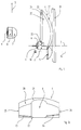
- Fig. 1 shows schematically a perspective side view of parts of a sensor according to the invention.
- the sensor has an infrared laser diode as transmitter 1 with attached collimator lens unit 2 for transmission of a transmission light beam along a transmission axis 3.
- An asymmetrically shaped reception multifocus lens 4 which is essentially a main direction of vertical extension in Fig. 1 5, has at its end facing the transmission axis 3 a semi-cylindrical recess 6. Grips around this recess 6 the multifocus lens 4 the collimator lens unit 2 such that its main direction of extension 5 is substantially perpendicular to the Transmission axis 3.
- the exact structural design of the multifocus lens 4 is explained in more detail below with reference to FIGS. 2a to 2c.
- Transmitter 1 On the opposite side of the multifocus lens 4 Transmitter 1 is a pilot transmitter light-emitting diode 10 with a pilot beam lens 11 arranged to emit a pilot light beam along a pilot beam transmission axis 12, which runs essentially parallel to the transmission axis 3. In the transmission direction of the pilot beam lens 11 and the multifocus lens 4 there is a flat protective disk 13.
- Fig. 1 means not shown in their position relative to each other within of a housing, the front of which is partially covered by the protective pane 13 is formed.
- the sensor shown in Fig. 1 serves as a reflection light scanner for detection of objects within a surveillance area that are essentially with one by imaging the transmitted light beam by the collimator lens unit 2 predetermined lateral extent extends along the transmission axis 3. If an object from the light of the Transmitter 1 is detected, it reflects this diffusely in the direction of Multifocus lens 4. Through its different zones, the reflected Light depending on the distance of the object from the sensor to the Receiving collective lens 7 and deflected by this onto the receiving element 9. This generates depending on the received light intensity an output signal, for example for comparison with a Threshold value forwarded to an evaluation unit, not shown in FIG. 1 can be.
- the mode of operation of the different zones of the multifocus lens 4 is explained below with reference to FIGS. 3a to 5b.
- the receiving collective lens 7 has a short focal length and is immediate arranged in front of the receiving element 9. Your hemispherical The light entry side has an opening area that is significantly larger than the photosensitive surface of the receiving element 9, for example by a factor of 10 to 100. This will change the size of the photosensitive Virtually increased area or can be the photosensitive area of the Receiving elements 9 to achieve a low level of electronic noise be kept really low.
- the reception collective lens enables 7 the compensation of adjustment errors between the transmission axis 3 and the optical axes of the light exit sides 22, 23, 24 of the different zones of the multifocus lens 4 up to ⁇ 3 °, and it allows thus easier and faster assembly of the sensor. Through the Use of the receiving collective lens 7 can also be less Reach the depth of the sensor.
- the pilot transmitter 10, 11 sends a visible pilot light beam along the Axis 12 off, the adjustment of the transmitter 1 and thus the sensor simplified.
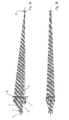
- Figures 2a, 2b and 2c show perspective side views and a view of the underside of the multifocus lens 4 of the sensor according to Fig. 1.
- the multifocus lens 4 has a light entry side 20 with a single aspherical surface. One opposite the light entry side 20
- the light exit side 21 of the multifocus lens 4 has three flat surfaces 22, 23, 24, which are each one for the illustration of a particular one Section of the monitoring area assigned to the effective zone are.
- the plane surface 22 for mapping a remote monitoring area effective zone takes up the majority of the light exit side 21 on.
- This remote plane surface 22 extends essentially within one plane perpendicular to the transmission axis 3 approximately to the level of Recess 6.
- the two close at this end of the plane surface 22 Flat surfaces 23, 24, which those zones of the multifocus lens 4th limit the side for imaging a surveillance close range or extremely close range are effective.
- the two flat surfaces 23, 24 each extend substantially opposite one side of the recess 6 from the end of the distal plane surface 22 the main direction of extent 5 to the height of the transmission axis 3.
- the surface normal of the near plane surface 23 is at an angle of approximately 91 ° to the main direction of extent 5 and closes with the transmission axis 3 an angle of approximately 5 °.
- the surface normal of the extreme near plane surface 24 includes with the main direction of extension 5 Angle of about 91.5 ° and with the transmission axis 3 an angle of about 11 °.
- the edge adjacent to the long plane surface 22 the near plane surface 23 and the extreme near plane surface 24 is in the direction the light entry side 20 of the multifocus lens 4.
- the three flat surfaces 22, 23, 24 are laterally parallel by one both to the transmission axis 3 and to the main direction of extent 5 running flat side surface 25 or 26 limited.
- FIG. 2c shows the underside of the multifocus lens 4 in a view in Main direction of extension 5.
- the underside of the for the illustration of a Zone or an extreme near zone effective zone has in each case roughly the outline of a trapezoid, the one on the light entry side 20 of the multifocus lens 4 adjacent side is curved accordingly the aspherical course of the surface 20.
- the view according to FIG. 2c is also the tilting of the near and extreme near plane surface 23 or 24 with respect to the main direction of extent 5.
- the tendencies the plane surfaces 23, 24 with respect to the transmission axis 3 or the main direction of extension 5 can also be chosen differently, depending on the desired Mapping properties of the corresponding zones.
- Figures 3a and 3b, 4a and 4b, and 5a and 5b each show in schematic side view or top view of the optical system of the 1 and illustrate by the drawn in Hatching the image of reflected or reflected light from a Object 27, which is far from the sensor or close the sensor or in the immediate vicinity of the sensor to which Receiving element 9 of the sensor by means of the respective effective zone Multifocus lens 4.
- the object is in the representation according to FIGS. 3a and 3b 27 in a remote monitoring area.
- the one for the illustration of this Object 27 onto the receiving collective lens 7 or the receiving element 9 effective zone of the multifocus lens 4 includes in particular that area the multifocus lens 4, which extends from the flat surface 22 on the light exit side 21 in the direction of the transmission axis 3 up to the light entry side 20 of the multifocus lens 4 extends.
- the one for imaging is a object 27 located in a surveillance close range Zone of the multifocus lens 4 is formed by that area that from the plane surface 23 parallel to the transmission axis to the light entry side 20 of the multifocus lens 4 extends. According to the representation in 4b, this zone is only within one Side half of the multifocus lens 4.
- FIGS. 3a to 5b the configuration of the Multifocus lens 4 with different zones with different, spatial focal points separated from one another are advantageous in a simple manner Extension of the monitoring area along the transmission axis 3 enables.
- Objects 27 in different sections of the surveillance area are not necessarily exclusively by means of the in each case in the corresponding zone designated above as effective the receiving element 9 is shown; in the transition area between neighboring ones Such sections of the surveillance area Imaging of the light reflected by an object 27 onto the receiving element 9 of the sensor, optionally by means of the two adjacent ones Zones corresponding to surveillance area sections.
- the different Surveillance area sections do not necessarily need to be straight can be arranged along the transmission axis 3, but can also be arranged laterally be staggered.
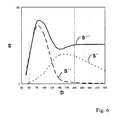
- Fig. 6 shows an example of the course of the in arbitrary units Amount of light S emitted at the receiving element 9 of the sensor according to FIG. 1 is obtained and from the reflection or remission of an object 27 in different sections of the surveillance area.
- the diagram shown is the distance D of in the horizontal direction Object 27 drawn in by the sensor in millimeters.
- the course of the amount of light S 'by imaging the object 27 originating light on the receiving element 9 by means of the only effective zone for the surveillance close range is short shown in dashed lines.
- the long dashed curve shows the amount of light S ", which are the only ones effective for the surveillance extreme close range Zone is mapped to the receiving element 9.
- the solid Line represents the total amount of light S "'that of all three zones the multifocus lens 4 is imaged on the receiving element 9.
- the amount of light S "' is the sum of the amounts of light S', S" and not individually shown amount of light that comes exclusively from the remote monitoring area assigned zone mapped to the receiving element 9 becomes.
- objects 27 are also in the surveillance close range or extremely close range a quantity of light similar to that which for objects 27 in the remote monitoring area at the receiving element 9 is obtained, mapped on this.
- the surveillance area is around the short-range section and the extreme short-range section extended towards the sensor. Only falls directly in front of the sensor the signal with a reduced distance D decreases sharply.
- the design of the multifocus lens 4 can be advantageously simple Be optimized.
- the light entry side 20 of the multifocus lens 4 has all zones common aspherical surface, the curvature of which for illustration of an object 27 within different sections of the surveillance area is optimized for the receiving element 9. Since it is the light entry side 20 around the only curved surface of the multifocus lens 4 acts, their production is very simple.
- the side of the lens In general, it is preferred if the side of the lens, the surface of which is a has a curved shape, has a differentiable course, in particular in cross section along a plane within which the transmission beam runs. This takes place on the corresponding side of the multifocus lens 4 no abrupt change in thickness of the multifocus lens 4, but it has a uniformly smooth surface, making it less is susceptible to contamination.
- the manufacture of the multifocus lens 4 is simplified if a zone of Multifocus lens 4, which in particular has a differentiable course opposite side, is formed as a flat surface.
- a zone of Multifocus lens 4 of the sensor according to FIG. 1 is the light exit side 21 of all zones each designed as a flat surface 22, 23, 24.
- the light exit side of at least one zone be curved, in particular aspherical or spherical surface to be formed enable further optimization of the imaging properties of this zone.
- two zones consists of, in particular, each as a plane surface 22, 23, 24 formed light exit side 21 with respect to one direction to be arranged parallel to the transmission axis 3 spatially offset from one another.
- the optical axis runs for the imaging of a Monitoring remote range provided on the receiving element 9 Zone on the light exit side 21 essentially parallel to the transmission axis 3rd
- the illustration of a surveillance close range or extremely close range the receiving element 9 takes place in the sensor according to FIG. 1 in an advantageously simple manner by the optical axis of the corresponding Zones 23 and 24 of the multifocus lens 4 on the light exit side 21 run at a non-zero angle to the transmission axis.
- the opening area of the light entry side 20 is the one for imaging the Monitoring remote area effective zone of the sensor according to FIG. 1 is significantly larger than the light entry sides 20 for the illustration of a surveillance close range or extremely close range effective Zones of the multifocus lens 4, these zones are each in a similar Solid angle acted upon by the light emitted by objects 27 is reflected in the different surveillance area sections.
- FIG. 6 approximately independent of the distance of the object 27 from the sensor a sufficient amount of light be mapped to the receiving element 9, so that its Sensitivity to this amount of light can be adjusted.
- the Invention also plane surfaces on the light entry side and at least one curved surface can be provided on the light exit side.
Landscapes
- Engineering & Computer Science (AREA)
- Physics & Mathematics (AREA)
- Computer Networks & Wireless Communication (AREA)
- General Physics & Mathematics (AREA)
- Radar, Positioning & Navigation (AREA)
- Remote Sensing (AREA)
- Electromagnetism (AREA)
- Lenses (AREA)
- Photometry And Measurement Of Optical Pulse Characteristics (AREA)
- Optical Radar Systems And Details Thereof (AREA)
- Geophysics And Detection Of Objects (AREA)
Applications Claiming Priority (2)
| Application Number | Priority Date | Filing Date | Title |
|---|---|---|---|
| DE19756541A DE19756541A1 (de) | 1997-12-18 | 1997-12-18 | Opto-elektronischer Sensor |
| DE19756541 | 1997-12-18 |
Publications (3)
| Publication Number | Publication Date |
|---|---|
| EP0924535A2 true EP0924535A2 (fr) | 1999-06-23 |
| EP0924535A3 EP0924535A3 (fr) | 2000-01-05 |
| EP0924535B1 EP0924535B1 (fr) | 2005-02-16 |
Family
ID=7852539
Family Applications (1)
| Application Number | Title | Priority Date | Filing Date |
|---|---|---|---|
| EP98124137A Expired - Lifetime EP0924535B1 (fr) | 1997-12-18 | 1998-12-18 | Capteur opto-électronique |
Country Status (2)
| Country | Link |
|---|---|
| EP (1) | EP0924535B1 (fr) |
| DE (2) | DE19756541A1 (fr) |
Cited By (4)
| Publication number | Priority date | Publication date | Assignee | Title |
|---|---|---|---|---|
| EP2101189A1 (fr) | 2008-03-14 | 2009-09-16 | Firma Pepperl + Fuchs GmbH | Capteur optique |
| EP2681799A4 (fr) * | 2011-03-03 | 2014-08-13 | Taoglas Group Holdings | Antenne à bande ultralarge à angles multiples avec procédés d'assemblage à technologie de montage en surface et kits associés |
| EP3002609A1 (fr) * | 2014-10-01 | 2016-04-06 | Sick Ag | Capteur optoelectronique |
| US9810626B2 (en) | 2015-04-08 | 2017-11-07 | Sick Ag | Optoelectronic sensor and method for the transmission monitoring of a front screen |
Families Citing this family (3)
| Publication number | Priority date | Publication date | Assignee | Title |
|---|---|---|---|---|
| DE10331074A1 (de) * | 2003-07-09 | 2005-02-03 | Conti Temic Microelectronic Gmbh | Sensoranordnung zur Abstands- und/oder Geschwindigkeitsmessung |
| DE102021122418B4 (de) | 2021-08-31 | 2025-01-16 | Sick Ag | Optoelektronischer Sensor und Verfahren zum Erfassen von Objekten in einem Überwachungsbereich |
| DE202021104670U1 (de) | 2021-08-31 | 2022-12-01 | Sick Ag | Optoelektronischer Sensor zum Erfassen von Objekten in einem Überwachungsbereich |
Family Cites Families (9)
| Publication number | Priority date | Publication date | Assignee | Title |
|---|---|---|---|---|
| DE1145365B (de) * | 1959-12-29 | 1963-03-14 | Ernst Befort | Lichtelektrische Abtastvorrichtung |
| DE1883592U (de) * | 1963-09-07 | 1963-11-28 | Erwin Sick | Lichtelektrische abtastvorrichtung. |
| DE1297006C2 (de) * | 1967-12-16 | 1973-12-06 | Endl Alfons | Reflex-Lichtschranke |
| DE3214406C1 (de) * | 1982-04-20 | 1983-06-01 | Elektro-Automation Dipl.-Ing. Joachim Pantel, 8520 Erlangen | Linse für ein Lichtsteuergerät |
| EP0363520A1 (fr) * | 1988-10-14 | 1990-04-18 | Wako Corporation | Détecteur photo-électrique |
| DE69225811T2 (de) * | 1991-09-13 | 1999-01-21 | Denso Corp | Optisches radar |
| GB2286042B (en) * | 1994-01-27 | 1998-07-29 | Security Enclosures Ltd | Wide-angle infra-red detection apparatus |
| DE4402642C2 (de) * | 1994-01-29 | 1995-11-23 | Leuze Electronic Gmbh & Co | Optoelektronische Vorrichtung zum Orten von Hindernissen |
| DE19619308A1 (de) * | 1996-05-13 | 1997-11-20 | Sick Ag | Kombinations-Lichttaster |
-
1997
- 1997-12-18 DE DE19756541A patent/DE19756541A1/de not_active Withdrawn
-
1998
- 1998-12-18 DE DE59812575T patent/DE59812575D1/de not_active Expired - Lifetime
- 1998-12-18 EP EP98124137A patent/EP0924535B1/fr not_active Expired - Lifetime
Cited By (5)
| Publication number | Priority date | Publication date | Assignee | Title |
|---|---|---|---|---|
| EP2101189A1 (fr) | 2008-03-14 | 2009-09-16 | Firma Pepperl + Fuchs GmbH | Capteur optique |
| EP2681799A4 (fr) * | 2011-03-03 | 2014-08-13 | Taoglas Group Holdings | Antenne à bande ultralarge à angles multiples avec procédés d'assemblage à technologie de montage en surface et kits associés |
| EP3002609A1 (fr) * | 2014-10-01 | 2016-04-06 | Sick Ag | Capteur optoelectronique |
| US9810626B2 (en) | 2015-04-08 | 2017-11-07 | Sick Ag | Optoelectronic sensor and method for the transmission monitoring of a front screen |
| EP3078985B1 (fr) * | 2015-04-08 | 2018-03-14 | Sick Ag | Capteur optoelectronique et procede de surveillance de transmission d'un disque frontal |
Also Published As
| Publication number | Publication date |
|---|---|
| DE59812575D1 (de) | 2005-03-24 |
| EP0924535A3 (fr) | 2000-01-05 |
| DE19756541A1 (de) | 1999-06-24 |
| EP0924535B1 (fr) | 2005-02-16 |
Similar Documents
| Publication | Publication Date | Title |
|---|---|---|
| EP1405037B1 (fr) | Dispositif de mesure optique de distance sur une plage de mesure etendue | |
| DE102007036492B4 (de) | Optische Sensorvorrichtung | |
| WO2019037809A1 (fr) | Dispositif d'émission pour un scanner lidar présentant un miroir de balayage recouvert par un élément de recouvrement | |
| DE102015119668B3 (de) | Optoelektronischer Sensor und Verfahren zur Erfassung eines Objekts | |
| DE102007027429B4 (de) | Radareinrichtung und optischer Empfänger dafür | |
| DE69608066T3 (de) | Optisches Gerät zum Abstandsmessen | |
| DE102012212150A1 (de) | Laserradarvorrichtung, die zwischen einem Kennzeichenschild und einemFahrzeugaufbau angeordnet ist | |
| DE4431889B4 (de) | Lichtstreuungstyp-Rauchsensor | |
| DE102005033349A1 (de) | Optischer Sensor | |
| EP0762153A2 (fr) | Système optique | |
| DE102016208713B4 (de) | Optoelektronischer Sensor | |
| DE102007030880B4 (de) | Vorrichtung zur Erfassung einer Objektszene | |
| EP3002609B1 (fr) | Capteur optoelectronique | |
| DE19860464C2 (de) | Laserentfernungsmeßgerät für große Meßbereiche | |
| EP1421430A1 (fr) | Dispositif de balayage | |
| DE102021122418B4 (de) | Optoelektronischer Sensor und Verfahren zum Erfassen von Objekten in einem Überwachungsbereich | |
| EP0924535B1 (fr) | Capteur opto-électronique | |
| EP1695109B1 (fr) | Dispositif pour mesurer la distance a des objets proches et eloignes | |
| EP3229042B1 (fr) | Capteur optoélectronique et procédé de détection et de détermination de distance par rapport à un objet | |
| EP4118405B1 (fr) | Détecteur de mouvement infrarouge | |
| DE102010003544A1 (de) | 3D-TOF-Kamera | |
| DE4407911C2 (de) | Optisches System mit einem Strahlung bündelnden und umlenkenden Optikkörper | |
| EP2737334A1 (fr) | Dispositif de mesure optique pour un véhicule | |
| DE102004003386C5 (de) | Optischer Sensor | |
| EP3553564B1 (fr) | Capteur mesurant la distance |
Legal Events
| Date | Code | Title | Description |
|---|---|---|---|
| PUAI | Public reference made under article 153(3) epc to a published international application that has entered the european phase |
Free format text: ORIGINAL CODE: 0009012 |
|
| AK | Designated contracting states |
Kind code of ref document: A2 Designated state(s): CH DE FR IT LI |
|
| AX | Request for extension of the european patent |
Free format text: AL;LT;LV;MK;RO;SI |
|
| PUAL | Search report despatched |
Free format text: ORIGINAL CODE: 0009013 |
|
| AK | Designated contracting states |
Kind code of ref document: A3 Designated state(s): AT BE CH CY DE DK ES FI FR GB GR IE IT LI LU MC NL PT SE |
|
| AX | Request for extension of the european patent |
Free format text: AL;LT;LV;MK;RO;SI |
|
| 17P | Request for examination filed |
Effective date: 20000211 |
|
| AKX | Designation fees paid |
Free format text: CH DE FR IT LI |
|
| GRAP | Despatch of communication of intention to grant a patent |
Free format text: ORIGINAL CODE: EPIDOSNIGR1 |
|
| GRAS | Grant fee paid |
Free format text: ORIGINAL CODE: EPIDOSNIGR3 |
|
| GRAA | (expected) grant |
Free format text: ORIGINAL CODE: 0009210 |
|
| AK | Designated contracting states |
Kind code of ref document: B1 Designated state(s): CH DE FR IT LI |
|
| REG | Reference to a national code |
Ref country code: CH Ref legal event code: EP |
|
| REF | Corresponds to: |
Ref document number: 59812575 Country of ref document: DE Date of ref document: 20050324 Kind code of ref document: P |
|
| PLBE | No opposition filed within time limit |
Free format text: ORIGINAL CODE: 0009261 |
|
| STAA | Information on the status of an ep patent application or granted ep patent |
Free format text: STATUS: NO OPPOSITION FILED WITHIN TIME LIMIT |
|
| ET | Fr: translation filed | ||
| 26N | No opposition filed |
Effective date: 20051117 |
|
| PGFP | Annual fee paid to national office [announced via postgrant information from national office to epo] |
Ref country code: FR Payment date: 20131213 Year of fee payment: 16 |
|
| PGFP | Annual fee paid to national office [announced via postgrant information from national office to epo] |
Ref country code: CH Payment date: 20141216 Year of fee payment: 17 |
|
| REG | Reference to a national code |
Ref country code: FR Ref legal event code: ST Effective date: 20150831 |
|
| PG25 | Lapsed in a contracting state [announced via postgrant information from national office to epo] |
Ref country code: FR Free format text: LAPSE BECAUSE OF NON-PAYMENT OF DUE FEES Effective date: 20141231 |
|
| PGFP | Annual fee paid to national office [announced via postgrant information from national office to epo] |
Ref country code: DE Payment date: 20151217 Year of fee payment: 18 |
|
| REG | Reference to a national code |
Ref country code: CH Ref legal event code: PL |
|
| PGFP | Annual fee paid to national office [announced via postgrant information from national office to epo] |
Ref country code: IT Payment date: 20151222 Year of fee payment: 18 |
|
| PG25 | Lapsed in a contracting state [announced via postgrant information from national office to epo] |
Ref country code: LI Free format text: LAPSE BECAUSE OF NON-PAYMENT OF DUE FEES Effective date: 20151231 Ref country code: CH Free format text: LAPSE BECAUSE OF NON-PAYMENT OF DUE FEES Effective date: 20151231 |
|
| REG | Reference to a national code |
Ref country code: DE Ref legal event code: R119 Ref document number: 59812575 Country of ref document: DE |
|
| PG25 | Lapsed in a contracting state [announced via postgrant information from national office to epo] |
Ref country code: IT Free format text: LAPSE BECAUSE OF NON-PAYMENT OF DUE FEES Effective date: 20161218 |
|
| PG25 | Lapsed in a contracting state [announced via postgrant information from national office to epo] |
Ref country code: DE Free format text: LAPSE BECAUSE OF NON-PAYMENT OF DUE FEES Effective date: 20170701 |