EP0924543A2 - Câble à fibres optiques avec capacité d'indication de contrainte et méthode pour sa fabrication - Google Patents
Câble à fibres optiques avec capacité d'indication de contrainte et méthode pour sa fabrication Download PDFInfo
- Publication number
- EP0924543A2 EP0924543A2 EP98310199A EP98310199A EP0924543A2 EP 0924543 A2 EP0924543 A2 EP 0924543A2 EP 98310199 A EP98310199 A EP 98310199A EP 98310199 A EP98310199 A EP 98310199A EP 0924543 A2 EP0924543 A2 EP 0924543A2
- Authority
- EP
- European Patent Office
- Prior art keywords
- stress
- layer
- cable
- cladding
- fiber
- Prior art date
- Legal status (The legal status is an assumption and is not a legal conclusion. Google has not performed a legal analysis and makes no representation as to the accuracy of the status listed.)
- Withdrawn
Links
Images

Classifications
-
- G—PHYSICS
- G02—OPTICS
- G02B—OPTICAL ELEMENTS, SYSTEMS OR APPARATUS
- G02B6/00—Light guides; Structural details of arrangements comprising light guides and other optical elements, e.g. couplings
- G02B6/44—Mechanical structures for providing tensile strength and external protection for fibres, e.g. optical transmission cables
- G02B6/4439—Auxiliary devices
- G02B6/4469—Security aspects
-
- G—PHYSICS
- G02—OPTICS
- G02B—OPTICAL ELEMENTS, SYSTEMS OR APPARATUS
- G02B6/00—Light guides; Structural details of arrangements comprising light guides and other optical elements, e.g. couplings
- G02B6/44—Mechanical structures for providing tensile strength and external protection for fibres, e.g. optical transmission cables
- G02B6/4401—Optical cables
- G02B6/4415—Cables for special applications
-
- G—PHYSICS
- G02—OPTICS
- G02B—OPTICAL ELEMENTS, SYSTEMS OR APPARATUS
- G02B6/00—Light guides; Structural details of arrangements comprising light guides and other optical elements, e.g. couplings
- G02B6/46—Processes or apparatus adapted for installing or repairing optical fibres or optical cables
- G02B6/56—Processes for repairing optical cables
- G02B6/562—Processes for repairing optical cables locatable, e.g. using magnetic means
Definitions
- the present invention relates generally to the field of optical fiber waveguides, and more particularly to a means for determining when an optical fiber waveguide has been mishandled and potentially damaged.
- Fiber optic technology is gaining increased attention as communication service providers design their networks to carry high bandwidth signals. Fiber optic technology is so attractive because of the tremendous bandwidth capability of light transmission. Light in the visible and near visible spectrum has characteristic frequencies exceeding hundreds of gigahertz (GHz) allowing information transmission at rates unattainable by traditional, twisted-pair technology.
- GHz gigahertz
- Fiber optic media have very low loss characteristics, particularly when compared to metallic media. Fiber optic cables are essentially immune to electromagnetic interference and do not generate any electromagnetic fields to interfere with other equipment. Inasmuch as fiber optic cables are nonconducting, they do not load electrical equipment - instead, the cables act as an optoisolator. Furthermore, fiber optic cables are small and lightweight and can be installed where twisted-pair copper wires will not fit. Lastly, optical fiber, despite its significant performance advantage, is price competitive with high-end twisted pair cable.
- optical fibers do have some disadvantages.
- Second, fiber optic cables must be treated with care during handling and installation to avoid damaging the waveguide. It has long been believed that the fiber itself is very fragile because it is made of glass. This belief, however, is false. Modern optical fibers have tensile strength ratings ranging from 600,000 - 800,000 pounds per square inch. Nevertheless, optical fibers are highly susceptible to damage when bent.
- the present invention is generally directed to a fiber optic cable having stress indicating means and a method for making same.
- the stress indicating means provides a cost effective method for determining whether an optical cable has been bent, stressed or otherwise mishandled, which may cause optical loss when the cable is placed in service.
- the fiber optic cable according to the instant invention includes an optical fiber, comprised of a core and a cladding, and a stress indicator concentrically disposed about the fiber that changes color when subjected to stress. By examining the color of the stress indicator, a technician can visually identify cables that have been bent or mishandled and subject them to testing before installation.
- the stress indicating means is a layer of multi-phase material, examples of which include polyolefins, properly cooled nylon and selected polymers.
- the stress indicator is concentrically disposed about the jacket of a generic cable or cord providing similar stress identification benefits.
- Optical fibers serve as a medium for transmitting light by virtue of a phenomenon known as total internal reflection.
- the basic fiber optic element comprises a glass or sometimes plastic core 10 that is enveloped by an outer concentric shell or cladding 12.
- Cladding 12 is generally made from glass and has a relatively low index of refraction with respect to core 10. Because of the difference in the index of refraction between the two materials, light rays striking cladding 12 at an angle greater than or equal to the critical angle ( ⁇ c ) will be reflected back into core 10 at an angle of reflection equal to the angle of incidence. Inasmuch as the angles of incidence and reflection are equal, the light ray will continue to zig-zag down the length of the fiber. If a light ray strikes cladding 12 at an angle less than the critical angle, however, the ray will be refracted and pass through cladding 12 thus escaping the fiber.
- FIG. 2 illustrates the adverse effects that bending can have on an optical fiber.
- the light ray would normally strike cladding 12 at an incident angle greater than ⁇ c ; however, the bending of the fiber causes the light ray to strike cladding 12 at an angle ⁇ that is less than ⁇ c causing the light ray to refract and escape the fiber. While it may appear that the fiber can be straightened to correct the problem, that unfortunately is not possible.
- kinks are introduced into the interface between core 10 and cladding 12. Whenever light rays strike these kinks, they are susceptible to escaping the fiber if the angle of incidence is less than the critical angle.
- the present invention provides a stress indication means by which customers and installers can visually identify cables that have been bent or treated roughly and should therefore be tested before being installed into a communication network.
- Fiber optic cables generally come in two varieties: tight-buffered cables and loose-tube cables.
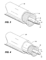
- An exemplary tight-buffered fiber optic cable embodying the principles of the present invention is shown in FIG. 3.
- the cable is comprised of several concentric layers enveloping one another in a cumulative fashion.
- At the center of the cable is an optical fiber comprised of core 10 and cladding 12 as discussed in the foregoing.
- the optical fiber comes in a variety of sizes typically identified using the following convention: core outer diameter/cladding outer diameter.
- a typical size for a single-mode fiber is 9/125 ⁇ m while multimode fibers are common in 50/125 ⁇ m, 62.5/125 ⁇ m and 100/140 ⁇ m sizes.
- cladding 12 is generally coated with an acrylic material cured by ultra-violet (UV) radiation to protect the glass fiber from dust and scratches.
- a thermoplastic buffer 14 Surrounding cladding 12 is a thermoplastic buffer 14 providing protection and forming what is commonly referred to as a "buffered fiber.”
- the outside diameter of buffer 14 is typically 900 ⁇ m, which is a common standard for many connectors and splicing tools.
- Traditional cables are generally completed with a layer of aramid strength material 16 and an outer jacket of polyvinyl chloride (PVC) 18.
- the aramid strength material typically comprises a KEVLAR_ yarn, which provides crush resistance and withstands the tensile stresses applied to the cable.
- Outer jacket 18 is designed to protect against environmental hazards such as abrasion, oil, solvents and other contaminates.
- the jacket generally defines the cable's duty and flammability rating. Obviously, heavy-duty cables will have thicker and tougher jackets than light-duty cables.
- the fiber optic cable according to the present invention includes a layer of stress indicating material 20 between buffer 14 and aramid strength material 16.
- stress indicating material 20 should be made from a multi-phase material. That is, a homogenous material capable of existing in physically distinct domains or states and whose opacity differs between the domains.
- Materials satisfying this criterion include the following: polyolefins (e.g., polyethylene, polypropylene, polybutene), nylon materials properly cooled ( i.e., quenched or annealed) after extrusion, polymethylmethacrylates, polystyrenes, and styrene-acrylonitrile polymers (e.g., acrylonitrile-butadient-styrene polymers). These materials all exhibit the property that physical stretching or bending causes a phase change from one domain to another resulting in a change in opacity and therefore color. When nylon is used, it may be desirable to cool the material via quenching for some applications while annealing will be preferred for other applications.
- polyolefins e.g., polyethylene, polypropylene, polybutene
- polymethylmethacrylates e.g., polysty
- the cooling process chosen will be the one that enhances the qualities desired for the given application (e.g., color, durability, rigidity, etc.).
- the multi-phase material chosen will be one that undergoes an irreversible phase change under stress. If the material returned to its original color after the stress was removed, the aim of providing a visual indicator that identifies potentially damaged products would be defeated.
- stress indicating material 20 is co-extruded on top of buffer 14.
- buffered fibers generally have a standardized outer diameter of 900 ⁇ m to adapt to splicing and connector equipment.
- stress indicating material 20 should be very thin, preferably in the range of 1 - 4 ⁇ m, to allow the buffered fiber to still comport with the tolerances allowed by the aforementioned equipment.
- buffered fibers are frequently color coded to distinguish, for example, between transmit and receive functions. Therefore, stress indicating material 20 is preferably transparent or displays the appropriate color in accordance with any color coding protocol when unstressed.
- buffer 14 itself could be manufactured from a stress indicating material and layer 20 eliminated. In this case, the multi-phase material chosen should be rugged enough to provide physical protection for the enclosed fiber in addition to changing color when placed under stress.
- the layers outside buffer 14 are typically stripped away leaving the buffered fiber to undergo potentially the roughest treatment during splicing and connecting. For that reason, the most common application for the present invention will be in providing stress indication for the buffered fiber, either by using stress indicating material for the buffer layer itself or by extruding a thin layer of stress indicating material outside of the buffer.
- FIG. 4 illustrates the same tight-buffered cable depicted in FIG. 3; however, in this instance, stress indicating material 20 is extruded onto the outside of outer jacket 18.
- outer jacket 18 is usually made from PVC and is designed to provide protection from the surrounding environs, the durability of the multi-phase material chosen for stress indicating material 20 need not be a consideration.
- outer jacket 18 could be eliminated and stress indicating material 20 extruded directly over aramid strength material 16 to fulfill both the stress indication and cable protection roles. In that configuration, a highly durable multi-phase material should be chosen to provide adequate protection for the enclosed fiber.
- FIG. 3 and FIG. 4 can be combined in which a stress indicating layer is provided for both the buffered fiber and the cable as a whole to detect possible mishandling of the cable or the buffered fiber after the outer layers have been stripped.
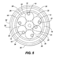
- FIG. 5 A loose-tube type of fiber optic cable is shown in FIG. 5.
- This type of cable is commonly installed outdoors or in harsh environments whereas the tight-buffered cable discussed in the foregoing is generally used for making internal connections inside a building.
- the loose tube cable employs a modular design in which several fibers comprising a core 10 and a cladding 12 are held in a stress indicating buffer tube 22 (only one fiber per tube is illustrated).
- the tube is generally filled with a gel that provides protection from moisture.
- the buffer tube is comprised of a stress indicating material that would provide a visual indication of when the fibers contained therein have been stressed or bent as discussed hereinbefore.
- the buffer tube serves merely to confine a collection of fibers and therefore does not have any strict thickness or dimension requirements.
- the stress indicating material chosen for the buffer tube should be dimensioned to hold the number of fibers that will be grouped together in the tube, should be capable of conforming to any color coding convention that may be required, and, in conjunction with the remaining components of the cable, should provide adequate protection for the fibers. Alternatively, a layer of stress indicating material (not shown) could be extruded onto the thermoplastic buffer tube to accomplish the same result.
- the remainder of the cable is designed with primary emphasis on withstanding the rigors of outdoor deployment.
- Buffer tubes 22 coil around central member 24, which is typically a steel wire or dielectric to act as reinforcement. The combination of buffer tubes 22 and central member 24 are held together by thermoplastic binder 26.
- Binder 26 is filled with an interstitial filling 28 to fill in the empty space between buffer tubes 22.
- a layer of aramid strength material 16 is disposed about binder 26.
- An inner jacket 30 and outer jacket 32 both made from PVC and separated by a layer of steel tape 34, provide sturdy protection from the outside elements. It may be desirable to extrude a layer of stress indicating material onto outer jacket 32 or manufacture outer jacket 32 from a stress indicating material; however, because of the bulk, strength and rigidity of the loose-tube cable, bending is normally not a problem until the outer layers are stripped and the individual buffer tubes 22 are handled to distribute or fan out the fibers to individual connectors. Therefore, buffer tubes 22 and binder 26 are the most likely candidates for use of the stress indicating material in a loose-tube cable.
Landscapes
- Physics & Mathematics (AREA)
- General Physics & Mathematics (AREA)
- Optics & Photonics (AREA)
- Engineering & Computer Science (AREA)
- Computer Security & Cryptography (AREA)
- Ropes Or Cables (AREA)
- Optical Fibers, Optical Fiber Cores, And Optical Fiber Bundles (AREA)
- Testing Of Optical Devices Or Fibers (AREA)
- Insulated Conductors (AREA)
Applications Claiming Priority (2)
| Application Number | Priority Date | Filing Date | Title |
|---|---|---|---|
| US995577 | 1997-12-22 | ||
| US08/995,577 US6108475A (en) | 1997-12-22 | 1997-12-22 | Optical fiber cable products having a stress indicating capability and process for making same |
Publications (2)
| Publication Number | Publication Date |
|---|---|
| EP0924543A2 true EP0924543A2 (fr) | 1999-06-23 |
| EP0924543A3 EP0924543A3 (fr) | 2000-04-26 |
Family
ID=25541956
Family Applications (1)
| Application Number | Title | Priority Date | Filing Date |
|---|---|---|---|
| EP98310199A Withdrawn EP0924543A3 (fr) | 1997-12-22 | 1998-12-11 | Câble à fibres optiques avec capacité d'indication de contrainte et méthode pour sa fabrication |
Country Status (4)
| Country | Link |
|---|---|
| US (1) | US6108475A (fr) |
| EP (1) | EP0924543A3 (fr) |
| JP (1) | JPH11248985A (fr) |
| CA (1) | CA2254805C (fr) |
Cited By (2)
| Publication number | Priority date | Publication date | Assignee | Title |
|---|---|---|---|---|
| EP1217350A1 (fr) * | 2000-12-21 | 2002-06-26 | Alcatel | Détecteur de la force de traction basé sur une insertion periodique des films tactiles changeantes de couleur pour détecter une manipulation incorrecte des fibres optiques |
| EP1942360A1 (fr) * | 2007-01-02 | 2008-07-09 | Teldor Wires and Cables Ltd. | Câbles hautement flexibles anti-rongeurs et étanches à l'eau, particulièrement utiles comme câbles de communication optiques |
Families Citing this family (17)
| Publication number | Priority date | Publication date | Assignee | Title |
|---|---|---|---|---|
| AR022233A1 (es) * | 1999-01-29 | 2002-09-04 | Siemens Ag | Cable de fibras opticas |
| KR20030030584A (ko) * | 2001-10-09 | 2003-04-18 | 글로벌광통신 (주) | 플라스틱 광섬유케이블 |
| US6798956B2 (en) * | 2002-07-16 | 2004-09-28 | Sun Microsystems, Inc. | Optical cable with indicator |
| US7054531B2 (en) * | 2002-12-23 | 2006-05-30 | Corning Cable Systems Llc | High density fiber optic premises cable with easy open units |
| US8992098B2 (en) | 2005-06-08 | 2015-03-31 | Commscope, Inc. Of North Carolina | Methods for forming connectorized fiber optic cabling |
| US7742667B2 (en) * | 2005-06-08 | 2010-06-22 | Commscope, Inc. Of North Carolina | Fiber optic cables and methods for forming the same |
| US7537393B2 (en) | 2005-06-08 | 2009-05-26 | Commscope, Inc. Of North Carolina | Connectorized fiber optic cabling and methods for forming the same |
| US10578812B2 (en) | 2005-06-08 | 2020-03-03 | Commscope, Inc. Of North Carolina | Methods for forming connectorized fiber optic cabling |
| US8043332B2 (en) * | 2006-09-29 | 2011-10-25 | Mattchen Terry M | Surgical cable providing visual indication of tension |
| US7356228B1 (en) * | 2007-01-12 | 2008-04-08 | International Business Machines Corporation | Fiber optic cable systems and methods incorporating a luminescent compound-containing layer to identify cracks |
| US7660893B2 (en) * | 2007-09-04 | 2010-02-09 | International Business Machines Corporation | Method and system for monitoring and instantly identifying faults in data communication cables |
| ES2325942B1 (es) * | 2007-11-08 | 2010-06-01 | Nordix S.A. | Cable de abonado para acometidas de fibra optica con autosoporte dielectrico. |
| NL1034923C2 (nl) * | 2008-01-16 | 2009-07-20 | Draka Comteq Bv | Optische kabel. |
| US20100278492A1 (en) | 2009-04-30 | 2010-11-04 | Bohler Gregory B | Armored Fiber Optic Assemblies and Methods of Forming Fiber Optic Assemblies |
| US9244046B2 (en) | 2012-12-03 | 2016-01-26 | International Business Machines Corporation | System for preventing undue bending of cables |
| CN209167604U (zh) * | 2018-06-27 | 2019-07-26 | 罗森伯格技术(昆山)有限公司 | 一种室外铠装光缆 |
| CN110596838B (zh) * | 2019-10-30 | 2020-06-09 | 江苏华脉光电科技有限公司 | 一种抗冰抗老化自承式光缆 |
Family Cites Families (17)
| Publication number | Priority date | Publication date | Assignee | Title |
|---|---|---|---|---|
| US3923198A (en) * | 1973-09-17 | 1975-12-02 | Minnesota Mining & Mfg | Stress-opacifiable tamper indicator |
| US3999946A (en) * | 1976-02-23 | 1976-12-28 | Allied Chemical Corporation | Time-temperature history indicators |
| US4330173A (en) * | 1976-03-22 | 1982-05-18 | Siemens Aktiengesellschaft | Conductor for optical cables |
| US4792053A (en) * | 1982-11-12 | 1988-12-20 | Tbl Development Corporation | Tamper-indicating capped container with angularly movable tine |
| US4513087A (en) * | 1983-01-31 | 1985-04-23 | The United States Of America As Represented By The Secretary Of The Navy | Reversible optical waveguide vapor sensor |
| US4905851A (en) * | 1983-02-18 | 1990-03-06 | Tri-Tech Systems International, Inc. | Tamper evident closures and packages with color changing means and separable portions of the closures and method of forming the same |
| US4489841A (en) * | 1983-02-18 | 1984-12-25 | Tri-Tech Systems International, Inc. | Tamper evident closures and packages |
| US4557505A (en) * | 1984-01-05 | 1985-12-10 | Minnesota Mining And Manufacturing Company | Stress-opacifying tamper indicating tape |
| DE3513592A1 (de) * | 1985-04-16 | 1986-10-16 | AEG KABEL AG, 4050 Mönchengladbach | Lichtwellenleiter |
| DE3704053C2 (de) * | 1987-02-10 | 1996-07-11 | Siemens Ag | Optische Ader mit einer einen Lichtwellenleiter lose umschließenden Hülle |
| US4864144A (en) * | 1988-08-25 | 1989-09-05 | Mclaughlin William L | Color-matched, ambient-light visual comparator dosimeter |
| US5135262A (en) * | 1990-06-20 | 1992-08-04 | Alcan International Limited | Method of making color change devices activatable by bending and product thereof |
| US5302350A (en) * | 1993-01-26 | 1994-04-12 | Fci - Fiberchem, Inc. | Specific and reversible carbon monoxide sensor |
| US5337376A (en) * | 1993-04-19 | 1994-08-09 | Hughes Aircraft Company | Chemically sensitive fiber optic cable |
| US5347041A (en) * | 1993-06-16 | 1994-09-13 | Edison Polymer Innovation Corporation | Molecular composites |
| US5501945A (en) * | 1994-08-30 | 1996-03-26 | The University Of Akron | Method of using multichromic polymers in packaging |
| US6415085B1 (en) * | 1995-08-01 | 2002-07-02 | At&T Corp. | Sub-miniature optical fiber cables, and apparatuses and methods for making the sub-miniature optical fiber cables |
-
1997
- 1997-12-22 US US08/995,577 patent/US6108475A/en not_active Expired - Fee Related
-
1998
- 1998-11-30 CA CA002254805A patent/CA2254805C/fr not_active Expired - Fee Related
- 1998-12-11 EP EP98310199A patent/EP0924543A3/fr not_active Withdrawn
- 1998-12-22 JP JP10364399A patent/JPH11248985A/ja active Pending
Cited By (4)
| Publication number | Priority date | Publication date | Assignee | Title |
|---|---|---|---|---|
| EP1217350A1 (fr) * | 2000-12-21 | 2002-06-26 | Alcatel | Détecteur de la force de traction basé sur une insertion periodique des films tactiles changeantes de couleur pour détecter une manipulation incorrecte des fibres optiques |
| US6442316B1 (en) | 2000-12-21 | 2002-08-27 | Alcatel | Stress sensor based on periodically inserted color-changing tactile films to detect mishandling of fiber optic cables |
| EP1942360A1 (fr) * | 2007-01-02 | 2008-07-09 | Teldor Wires and Cables Ltd. | Câbles hautement flexibles anti-rongeurs et étanches à l'eau, particulièrement utiles comme câbles de communication optiques |
| US7885501B2 (en) | 2007-01-02 | 2011-02-08 | Teldor Wires & Cables Ltd. | Highly flexible water-proof, rodent-proof cables particularly useful as optical communication cables |
Also Published As
| Publication number | Publication date |
|---|---|
| JPH11248985A (ja) | 1999-09-17 |
| CA2254805C (fr) | 2003-08-05 |
| CA2254805A1 (fr) | 1999-06-22 |
| US6108475A (en) | 2000-08-22 |
| EP0924543A3 (fr) | 2000-04-26 |
Similar Documents
| Publication | Publication Date | Title |
|---|---|---|
| CA2254805C (fr) | Produits de fibre optique pouvant indiquer la contrainte et processus de fabrication | |
| AU2006232206B2 (en) | Fiber optic drop cables suitable for outdoor fiber to the subscriber applications | |
| US8718427B2 (en) | Fiber optic cables and methods for forming the same | |
| US6185352B1 (en) | Optical fiber ribbon fan-out cables | |
| AU2013248177B2 (en) | An optical fiber cable | |
| US6389204B1 (en) | Fiber optic cables with strength members and methods of making the same | |
| CA1251972A (fr) | Cable a fibres optiques pour vide technique | |
| CN102782551B (zh) | 多光纤子单元电缆 | |
| US20050213900A1 (en) | Protective casings for optical fibers | |
| US10481359B2 (en) | Cylindrical enclosure for optical waveguide cable | |
| EP2753965A2 (fr) | Câbles d'intérieur/d'extérieur ou destinés à une installation extérieure compacts et bon marché | |
| EP4239386B1 (fr) | Câble à fibre optique avec éléments de renfort allongés et son procédé de fabrication | |
| EP4421549A2 (fr) | Câble à fibres optiques à chute aérienne | |
| Popescu et al. | Technique for Testing Optical Fibers by Using Electronic Microscopy | |
| Nakahara et al. | Optical cable design and characterization in Japan | |
| Hogari et al. | Novel Optical Fiber Cable with Small Cable Diameter Employing Rollable 20-Fiber Ribbons | |
| Yamada et al. | Ultra-high-density optical fiber cable and its application as pre-connectorized cable with adjustable excess length | |
| HK1124396B (en) | Fiber optic cables and methods for forming the same |
Legal Events
| Date | Code | Title | Description |
|---|---|---|---|
| PUAI | Public reference made under article 153(3) epc to a published international application that has entered the european phase |
Free format text: ORIGINAL CODE: 0009012 |
|
| AK | Designated contracting states |
Kind code of ref document: A2 Designated state(s): DE FR GB |
|
| AX | Request for extension of the european patent |
Free format text: AL;LT;LV;MK;RO;SI |
|
| PUAL | Search report despatched |
Free format text: ORIGINAL CODE: 0009013 |
|
| AK | Designated contracting states |
Kind code of ref document: A3 Designated state(s): AT BE CH CY DE DK ES FI FR GB GR IE IT LI LU MC NL PT SE |
|
| AX | Request for extension of the european patent |
Free format text: AL;LT;LV;MK;RO;SI |
|
| 17P | Request for examination filed |
Effective date: 20001011 |
|
| AKX | Designation fees paid |
Free format text: DE FR GB |
|
| 17Q | First examination report despatched |
Effective date: 20010131 |
|
| STAA | Information on the status of an ep patent application or granted ep patent |
Free format text: STATUS: THE APPLICATION HAS BEEN WITHDRAWN |
|
| 18W | Application withdrawn |
Effective date: 20030930 |