EP0924640A2 - Adapter zum Kontaktieren von Chipkarten - Google Patents
Adapter zum Kontaktieren von Chipkarten Download PDFInfo
- Publication number
- EP0924640A2 EP0924640A2 EP98122337A EP98122337A EP0924640A2 EP 0924640 A2 EP0924640 A2 EP 0924640A2 EP 98122337 A EP98122337 A EP 98122337A EP 98122337 A EP98122337 A EP 98122337A EP 0924640 A2 EP0924640 A2 EP 0924640A2
- Authority
- EP
- European Patent Office
- Prior art keywords
- cover plate
- adapter according
- chip card
- lower cover
- adapter
- Prior art date
- Legal status (The legal status is an assumption and is not a legal conclusion. Google has not performed a legal analysis and makes no representation as to the accuracy of the status listed.)
- Granted
Links
Images

Classifications
-
- G—PHYSICS
- G06—COMPUTING OR CALCULATING; COUNTING
- G06K—GRAPHICAL DATA READING; PRESENTATION OF DATA; RECORD CARRIERS; HANDLING RECORD CARRIERS
- G06K7/00—Methods or arrangements for sensing record carriers, e.g. for reading patterns
- G06K7/0013—Methods or arrangements for sensing record carriers, e.g. for reading patterns by galvanic contacts, e.g. card connectors for ISO-7816 compliant smart cards or memory cards, e.g. SD card readers
- G06K7/0021—Methods or arrangements for sensing record carriers, e.g. for reading patterns by galvanic contacts, e.g. card connectors for ISO-7816 compliant smart cards or memory cards, e.g. SD card readers for reading/sensing record carriers having surface contacts
-
- Y—GENERAL TAGGING OF NEW TECHNOLOGICAL DEVELOPMENTS; GENERAL TAGGING OF CROSS-SECTIONAL TECHNOLOGIES SPANNING OVER SEVERAL SECTIONS OF THE IPC; TECHNICAL SUBJECTS COVERED BY FORMER USPC CROSS-REFERENCE ART COLLECTIONS [XRACs] AND DIGESTS
- Y10—TECHNICAL SUBJECTS COVERED BY FORMER USPC
- Y10S—TECHNICAL SUBJECTS COVERED BY FORMER USPC CROSS-REFERENCE ART COLLECTIONS [XRACs] AND DIGESTS
- Y10S439/00—Electrical connectors
- Y10S439/945—Adapter for pcb or cartridge
Definitions
- the invention relates to an adapter for contacting chip cards a connection, preferably standardized according to the PCMCIA standard Data processing device or the like, consisting of a card-shaped housing with an upper and lower cover plate, the an insertion slot at the end opening into a receiving channel for the inclusion of a chip card and one on the opposite end has arranged connector panel, and from one with the connector panel electrically connected printed circuit board, which is parallel to the receiving channel extends and with contact elements for contacting a chip card is provided.
- a connection preferably standardized according to the PCMCIA standard Data processing device or the like, consisting of a card-shaped housing with an upper and lower cover plate, the an insertion slot at the end opening into a receiving channel for the inclusion of a chip card and one on the opposite end has arranged connector panel, and from one with the connector panel electrically connected printed circuit board, which is parallel to the receiving channel extends and with contact elements for contacting a chip card is provided.
- chip cards in the above sense card-shaped Carrier elements of electronic components, especially microprocessors, on which various, retrievable information can be stored, Understood.
- chip cards are particularly in the area of Computer technology can be found and enjoy one more and more spreading in connection with the authentication of Subjects.
- identity card for, for example, the Operation of access control systems
- chip cards are currently increasingly used in cashless payments, where they for example with credit cards or in the context of POS systems Remove the magnetic stripe card.
- Known reading units for example in the form of an adapter system enable a chip card to a standardized according to PCMCIA standard Connection of a data processing system.
- the state of the art Technology known adapters for this have a PCMCIA connector socket with a PCMCIA slot on the data processing system causes mechanical and electrical contacting. Reading the In this case, the chip card is arranged in the receiving channel for the chip card Contact elements which touch the same or, for example, on optical or magnetic path, contactless.
- a contact unit for card-shaped Carrier elements of electronic assemblies known with a base plate with one for the plane-parallel recording of a card-shaped support element suitable size, at least one substantially parallel to the base plate arranged circuit board with contact elements for the electronic Assemblies of the support element on their surface and with one on one Edge of the base plate arranged connector panel is provided.
- One for Base plate essentially congruent, plate-shaped cover element forms a slot-like insertion channel with the circuit board and is in the area of the connector panel and the corners opposite this at the Base plate attached. The attachment in the area of the connection panel takes place thereby over two webs running to the side of the connection field, which are in one piece are connected to the base plate and the cover element.
- the invention is based on the object of developing an adapter for contacting chip cards with a connection of a data processing device or the like, preferably standardized according to the PCMCIA standard, in such a way that simple and inexpensive production can be achieved, which is economical in mass production in view of the increasingly extensive use guaranteed card systems.
- an adapter of the type mentioned according to the invention in that the top and bottom cover are two separate congruent components, and that an intermediate element is provided between the upper and lower cover plate, at least that thisête each other.
- An adapter designed in this way is simple and inexpensive manufacture and therefore allows mass production in the aforementioned Sense. This is due to the fact that, on the one hand, due to the two-part design with an upper and lower cover plate a simple Assembly results and secondly due to the connection of the cover plates a need-based use also via the intermediate elements different materials with little manufacturing effort can be achieved. Possible areas of application for the latter can for example in the need-based use of non-conductive or conductive materials for the cover plates with regard to a required Shielding, static dissipation and the like exist.
- the upper cover plate is with a provide upper and lower cover plates with lower intermediate elements, which are connected to each other at their opposite contact surfaces are.
- This has the advantage that the respective cover plates and associated intermediate elements can be prefabricated, so that after completed with a simple circuit board and connector panel Connection of the same upper and lower intermediate elements possible is.
- at the top and the lower intermediate elements correspondingly designed pins and Openings are arranged for easy and quick centering of the to achieve intermediate elements to be arranged, which then by means of ultrasonic welding, gluing or other material bonding with each other can be connected.
- the upper and the lower intermediate elements with correspondingly designed pins and Provide openings in the form of a plug connection and detachable with each other connected.
- the upper and lower ones Intermediate elements injection molded plastic parts by injection molding on the respective upper and lower cover plate can be fastened so that both simple and inexpensive manufacture of the intermediate elements as well as a reliable connection of the latter with the cover plates can be achieved.
- the upper and the lower are expedient Cover plate each provided with molded cramps, which in the upper and the respective lower intermediate elements are cast to a to ensure reliable, integral connection.
- the upper intermediate element formed as a substantially U-shaped frame
- the outer contour of the the upper cover plate follows and its inner contour clamping and Guide sections for receiving the circuit board between the two Has legs of the frame.
- the surface of the receiving channel facing in the region of the insertion slot arranged base of the frame on a Provide side with a flat recess This allows something slanted and thus easy insertion of a chip card into the slot of the adapter.
- the lower intermediate elements are approximately the height of a chip card having spacing segments that on the one hand in the front area of the chip card in the direction of insertion Form housing closed side walls of the slot and on the other hand, leaving the slot at the side subsequent receiving channel arranged on both sides of the connector panel are. In this way, safe guidance and contacting a Chip card ensured in the adapter.
- the side enables Release according to PCMCIA standard of type I, II, III or IV Dimensions of the card-shaped housing.
- the spacer segments are in one piece with one to the lower one Cover plate formed congruent base plate.
- the on both sides of the Terminal field arranged spacing segments on their opposite Inner surfaces of clamping sections for fixing the connection panel, so that simple and quick installation is guaranteed.
- the spacing segment arranged in the region of the insertion slot Inlet bevels for a chip card to be inserted and the on both sides of the Connection field arranged spacing segments with the insertion depth of one Chip card stops on the corner, which have a shape at the corner have the contour adapted to the chip card.
- the top cover plate on the insertion slot having a front face by several recessed, partially circular Has recesses formed contour.
- the ergonomic handling further favored in that the lower cover plate on the Insertion slot end face in at least one of the two outer, part-circular recesses of the upper cover plate opposite area pulled out like a lower lip Has surface on which at least one clamping cam is arranged by the together with the stops formed on the spacer segments the chip card can be secured. This also helps to ensure contact security is significantly increased.
- the upper and lower cover plates are made of metal, in addition to a good shielding to achieve robust and durable construction.
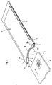
- the adapter shown in Fig. 1 has a housing 1, the Dimensions correspond to those of a Type II PCMCIA plug-in card.
- the Housing 1 is on its narrower end with a PCMCIA connector 2 provided, which - as can be seen from Fig. 3 - is completely housed in the housing 1.
- the housing 1 points to the Plug connection socket 2 opposite end face an insertion slot 3rd for a chip card 4, which is in a laterally open receiving channel 5 transforms.
- the chip card 4 is provided with a flat contact field 6 and can be inserted into the housing 1 in the direction of the double arrow shown or pull out.
- the side walls 7 are in the The area of the insertion slot 3 with frontal bevels 8 and the the receiving channel 5 facing ceiling surface with a sloping Provide allowable recess 9.
- An easy removal of one inserted chip card 4 is replaced by several recessed, Partially circular recesses 10, 10a on the contour of the insertion slot 3 end face and the recesses 10a opposite, surfaces 11 drawn out in the manner of a lower lip, which provide a user with cheap access to chip card 4.
- the Surfaces 11 serve at the same time as support surfaces for the chip card 4 Introduce, making this much easier.
- the surfaces 11 are also included slightly raised clamp cams 12 provided one insert the inserted chip card 4 in the receiving channel 5 and thus insert it Prevent unwanted slipping out.
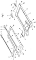
- the housing 1 consists of an upper Cover plate 13 and a lower cover plate 14 through Intermediate elements 15, 16, 17, 17a are connected to one another.
- Sheet metal stamped cover plates 13, 14 are orthogonal angled staples 18, 18a, 18b on during the manufacture of the Intermediate elements 15 to 17a by plastic injection molding them be included so that a simple yet resilient Connection of intermediate elements 15 to 17a and cover elements 13, 14 is ensured despite different materials.
- the intermediate element 15 arranged on the upper cover plate 13 is as formed a substantially U-shaped frame, the legs of their inner contour clamping and guide sections 19, 20 for receiving a Have circuit board 21, while the base of the intermediate element 15 with the previously mentioned inlet slopes 8, the recess 9 and the Recesses 10, 10a is provided. Due to the frame-like design of the intermediate element 15 is a high torsional rigidity of the housing 1 guaranteed.
- the trained as spacer segments Intermediate elements 16 to 17a have one of a chip card 4 approximately appropriate height and thereby form the receiving channel 5.
- the im Area of the insertion slot 3 arranged intermediate element 16 has a Base plate on the front of the contour of the lower cover plate 14 follows and thereby also the previously mentioned surfaces 11, on which the Metal or plastic existing clamping cams 12 as separate parts or are arranged in one piece, forms.
- the in the field of Plug connection socket 2 arranged intermediate elements 17, 17a assign the clamping sections 19 corresponding clamping sections 19a, the together with the aforementioned those with the circuit board 21 electrically Take the connected plug socket 2.
- a chip card 4 front end of the intermediate elements 17, 17a Stops 24 with a contour adapted to the corner shape of a chip card 4 provided that limit the insertion depth of a chip card 4 on the corner.
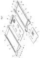
- the lower cover plate 14 has a Recess 25 in which a reinforcing plate 26 is arranged.
- the intermediate elements 16 to 17a are in one piece with one embodiment Bottom plate 27 formed, the 18c with the lower Cover plate 14 is connected.
- the necessary torsional rigidity of the housing 1 on the base plate 27 reached so that on the reinforcing plate 26 and the necessary Indentation 25 in the lower cover plate 14 can be dispensed with if necessary can.
- the adapter described above is suitable for connection to a PCMCIA interface of a computer or the like, the Recording channel 5 for a chip card 4 standardized according to DIN ISO 7816 is designed. That arranged on the top of the chip card 4 Contact field 6 comes with chip card 4 inserted into the adapter to lie opposite contact elements 28, so that contacting is ensured. Because of the suitability of the adapter for a DIN ISO 7816 standardized chip cards 4, in which the card width is the width of the PCMCIA standard conforming to housing 1 is a side Leaving the recording channel 5 indispensable.
- a contingent Impairment of the torsional rigidity and robustness of the housing 1 is by the design of the upper intermediate element 15 as in essential U-shaped frame and the provision of the stiffening plate 26 minimized so that they are largely excluded in practice can be.
- By providing pins 23 and more Corresponding openings 22 will be quick and easy to install Production achieved that is suitable for economical mass production and in the case of a detachable plug-in connection, it is also recycling-related Meets requirements.
Landscapes
- Engineering & Computer Science (AREA)
- Artificial Intelligence (AREA)
- Computer Vision & Pattern Recognition (AREA)
- Physics & Mathematics (AREA)
- General Physics & Mathematics (AREA)
- Theoretical Computer Science (AREA)
- Coupling Device And Connection With Printed Circuit (AREA)
- Credit Cards Or The Like (AREA)
- Details Of Connecting Devices For Male And Female Coupling (AREA)
Abstract
Description
- Fig. 1
- in einer perspektivischen Ansicht einen Adapter und eine Chipkarte;
- Fig. 2
- eine Explosionsdarstellung von einer oberen und einer unteren Abdeckplatte mit jeweils zugehörigen Zwischenelementen;
- Fig. 3
- in einer perspektivischen Ansicht eine mit einem Anschlußfeld versehene Leiterplatte sowie mit den Zwischenelementen verbundene obere und untere Abdeckplatte und
- Fig. 4
- eine Explosionsdarstellung von oberer und unterer Abdeckplatte mit zugehörigen Zwischenelementen in einer alternativen Ausführungsform.
- 1
- Gehäuse
- 2
- Steckanschlußbuchse
- 3
- Einschubschlitz
- 4
- Chipkarte
- 5
- Aufnahmekanal
- 6
- Kontaktfeld
- 7
- Wandung
- 8
- Einlaufschräge
- 9
- Ausnehmung
- 10
- Aussparung
- 10a
- Aussparung
- 11
- Fläche
- 12
- Klemmnocken
- 13
- obere Abdeckplatte
- 14
- untere Abdeckplatte
- 15
- Zwischenelement
- 16
- Zwischenelement
- 17
- Zwischenelement
- 17a
- Zwischenelement
- 18
- Krampen
- 18a
- Krampen
- 18b
- Krampen
- 18c
- Krampen
- 19
- Klemmabschnitt
- 19a
- Klemmabschnitt
- 20
- Führungsabschnitt
- 21
- Leiterplatte
- 22
- Öffnung
- 23
- Zapfen
- 24
- Anschlag
- 25
- Vertiefung
- 26
- Verstärkungsplatte
- 27
- Bodenplatte
- 28
- Kontaktelemente
Claims (17)
- Adapter zum Kontaktieren von Chipkarten (4) mit einem vorzugsweise nach PCMCIA-Standard genormten Anschluß eines Datenverarbeitungsgeräts oder dergleichen, bestehend aus einem steckkartenförmigen Gehäuse (1) mit einer oberen und unteren Abdeckplatte (13, 14), das einen stirnseitigen, in einen Aufnahmekanal (5) mündenden Einschubschlitz (3) für die Aufnahme einer Chipkarte (4) und ein an der gegenüberliegenden Stirnseite angeordnetes Anschlußfeld (2) aufweist, sowie aus einer mit dem Anschlußfeld (2) elektrisch verbundenen Leiterplatte (21), die sich parallel zum Aufnahmekanal (5) erstreckt und mit Kontaktelementen (28) zum Kontaktieren einer Chipkarte (4) versehen ist,
dadurch gekennzeichnet,
daß die obere und untere Abdeckplatte zwei getrennte, deckungsgleiche Bauteile sind, und daß zwischen oberer und unterer Abdeckplatte wenigstens ein Zwischenelement vorgesehen ist, welche diese miteinander verbindet. - Adapter nach Anspruch 1, dadurch gekennzeichnet, daß die obere Abdeckplatte (13) mit einem oberen (15) und die untere Abdeckplatte (14) mit unteren (16 bis 17a) Zwischenelementen versehen ist, die an ihren gegenüberliegenden Berührungsflächen miteinander verbunden sind.
- Adapter nach Anspruch 2, dadurch gekennzeichnet, daß an dem oberen (15) und den unteren (16 bis 17a) Zwischenelementen korrespondierend ausgebildete Zapfen (23) und Öffnungen (22) angeordnet sind.
- Adapter nach Anspruch 3, dadurch gekennzeichnet, daß das obere (15) und die unteren (16 bis 17a) Zwischenelemente mit korrespondierend ausgebildeten Zapfen (23) und Öffnungen (22) in Form einer Steckverbindung versehen und lösbar miteinander verbunden sind.
- Adapter nach einem der Ansprüche 1 bis 4, dadurch gekennzeichnet, daß das obere (15) und die unteren (16 bis 17a) Zwischenelemente Kunststoff-Spritzteile sind, die mittels Spritzgießen an der jeweiligen oberen und unteren Abdeckplatte (13, 14) befestigbar sind.
- Adapter nach Anspruch 5, dadurch gekennzeichnet, daß die obere und die untere Abdeckplatte (13, 14) jeweils mit angeformten Krampen (18 bis 18c) versehen sind, die in dem oberen und dem jeweiligen unteren Zwischenelementen (15 bis 17a) eingegossen sind.
- Adapter nach einem der Ansprüche 1 bis 6, dadurch gekennzeichnet, daß das obere Zwischenelement (15) als im wesentlichen U-förmiger Rahmen ausgebildet ist, dessen Außenkontur der der oberen Abdeckplatte (13) folgt und dessen Innenkontur Klemm- und Führungsabschnitte (19, 20) zur Aufnahme der Leiterplatte (21) zwischen den beiden Schenkeln des Rahmens aufweist.
- Adapter nach Anspruch 7, dadurch gekennzeichnet, daß die dem Aufnahmekanal (5) zugewandte Fläche der im Bereich des Einschubschlitzes (3) angeordneten Basis des Rahmens an einer Seite mit einer flächigen Ausnehmung (9) versehen ist.
- Adapter nach einem der Ansprüche 1 bis 8, dadurch gekennzeichnet, daß die unteren Zwischenelemente (16 bis 17a) annähernd die Höhe einer Chipkarte (4) aufweisende Abstandssegmente sind, die einerseits im in Einschubrichtung einer Chipkarte (4) vorderen Bereich des Gehäuses (1) geschlossene seitliche Wandungen (7) des Einschubschlitzes (3) bilden und andererseits unter seitlichem Freilassen des sich an den Einschubschlitz (3) anschließenden Aufnahmekanals (5) beidseitig des Anschlußfelds (2) angeordnet sind.
- Adapter nach Anspruch 9, dadurch gekennzeichnet, daß das im Bereich den Einschubschlitzes (3) angeordnete Abstandssegment (16) einstückig mit einer Bodenplatte ausgebildet ist, deren Außenkontur der der unteren Abdeckplatte (14) entspricht.
- Adapter nach Anspruch 10, dadurch gekennzeichnet, daß die untere Abdeckplatte (14) mit einer Vertiefung (25) versehen ist, in der eine vorzugsweise metallene Verstärkungsplatte (26) angeordnet ist.
- Adapter nach Anspruch 9, dadurch gekennzeichnet, daß die Abstandssegmente (16 bis 17a) einstückig mit einer zur unteren Abdeckplatte (14) deckungsgleichen Bodenplatte (27) ausgebildet sind.
- Adapter nach einem der Ansprüche 9 bis 12, dadurch gekennzeichnet, daß die beidseitig des Anschlußfeldes (2) angeordneten Abstandssegmente (17, 17a) an ihren gegenüberliegenden Innenflächen Klemmabschnitte (19a) zur Fixierung des Anschlußfeldes (2) aufweisen.
- Adapter nach einem der Ansprüche 9 bis 13, dadurch gekennzeichnet, daß das im Bereich des Einschubschlitzes (3) angeordnete Abstandssegment (16) mit Einlaufschrägen (8) für eine einzuführende Chipkarte (4) und die beidseitig des Anschlußfeldes (2) angeordneten Abstandssegmente (17, 17a) mit die Einstecktiefe einer Chipkarte (4) eckseitig begrenzenden Anschlägen (24), welche eine an die Eckenform der Chipkarte (4) angepaßte Kontur aufweisen, versehen sind.
- Adapter nach einem der Ansprüche 1 bis 14, dadurch gekennzeichnet, daß die obere Abdeckplatte (13) an der den Einschubschlitz (3) aufweisenden Stirnseite eine durch mehrere zurückspringende, teilkreisförmige Aussparungen (10, 10a) gebildete Kontur aufweist.
- Adapter nach Anspruch 15, dadurch gekennzeichnet, daß die untere Abdeckplatte (14) an der den Einschubschlitz (13) aufweisenden Stirnseite in zumindest einem der beiden äußeren teilkreisförmigen Aussparungen (10a) der oberen Abdeckplatte (13) gegenüberliegenden Bereich eine nach Art einer Unterlippe hervorgezogene Fläche (11) aufweist, auf der wenigstens ein Klemmnocken (12) angeordnet ist, durch den zusammen mit den an den Abstandssegmenten (17, 17a) ausgebildeten Anschlägen (24) die Chipkarte (4) sicherbar ist.
- Adapter nach einem der vorhergehenden Ansprüche, dadurch gekennzeichnet, daß die obere und die untere Abdeckplatte (13, 14) aus Metall gefertigt sind.
Applications Claiming Priority (2)
| Application Number | Priority Date | Filing Date | Title |
|---|---|---|---|
| DE29722142U DE29722142U1 (de) | 1997-12-16 | 1997-12-16 | Adapter zum Kontaktieren von Chipkarten |
| DE29722142U | 1997-12-16 |
Publications (3)
| Publication Number | Publication Date |
|---|---|
| EP0924640A2 true EP0924640A2 (de) | 1999-06-23 |
| EP0924640A3 EP0924640A3 (de) | 2000-10-11 |
| EP0924640B1 EP0924640B1 (de) | 2005-05-18 |
Family
ID=8049992
Family Applications (1)
| Application Number | Title | Priority Date | Filing Date |
|---|---|---|---|
| EP98122337A Expired - Lifetime EP0924640B1 (de) | 1997-12-16 | 1998-11-25 | Adapter zum Kontaktieren von Chipkarten |
Country Status (4)
| Country | Link |
|---|---|
| US (1) | US6272017B1 (de) |
| EP (1) | EP0924640B1 (de) |
| JP (1) | JP2000003416A (de) |
| DE (2) | DE29722142U1 (de) |
Cited By (3)
| Publication number | Priority date | Publication date | Assignee | Title |
|---|---|---|---|---|
| EP1143371A3 (de) * | 2000-04-04 | 2002-10-30 | J.S.T. Mfg. Co., Ltd. | Elektrischer Verbinder |
| WO2003107254A1 (de) * | 2002-06-13 | 2003-12-24 | Stocko Contact Gmbh & Co. Kg | Chipkartenleser im pc kartenformat |
| AU2009200080B2 (en) * | 1999-11-01 | 2011-09-22 | Respironics, Inc | Method and apparatus for monitoring and controlling a medical device |
Families Citing this family (33)
| Publication number | Priority date | Publication date | Assignee | Title |
|---|---|---|---|---|
| US6522299B2 (en) * | 1999-04-08 | 2003-02-18 | Cypress Semiconductor Corp. | PC card retractable antenna |
| JP2000305662A (ja) * | 1999-04-23 | 2000-11-02 | Jst Mfg Co Ltd | カード接続用アダプタ |
| DE29909222U1 (de) * | 1999-05-28 | 1999-08-05 | STOCKO Contact GmbH & Co. KG, 42327 Wuppertal | PC-Card Chipkartenleser |
| JP2000357548A (ja) * | 1999-06-16 | 2000-12-26 | Kel Corp | カード用コネクタ |
| US6470284B1 (en) * | 1999-08-05 | 2002-10-22 | 02 Micro International Limited | Integrated PC card host controller for the detection and operation of a plurality of expansion cards |
| JP5201543B2 (ja) * | 2000-09-06 | 2013-06-05 | 日立マクセル株式会社 | Icカードのリーダ・ライタ |
| US6760229B2 (en) * | 2000-10-18 | 2004-07-06 | Hewlett-Packard Development Company, L.P. | System for protecting electronic components |
| US6498731B1 (en) * | 2000-10-18 | 2002-12-24 | Compaq Computer Corporation | System for protecting electronic components |
| JP4763223B2 (ja) * | 2001-01-26 | 2011-08-31 | ソニー株式会社 | Icカード |
| US6461170B1 (en) * | 2001-05-17 | 2002-10-08 | 3Com Corporation | Stacked electronic integrated card assembly with multi-function shared interface |
| JP3894031B2 (ja) * | 2001-05-22 | 2007-03-14 | 株式会社村田製作所 | カード型携帯装置 |
| DE20117188U1 (de) * | 2001-10-19 | 2002-01-03 | STOCKO Contact GmbH & Co. KG, 42327 Wuppertal | Adapter zum Kontaktieren von Chipkarten |
| TW534499U (en) * | 2001-11-07 | 2003-05-21 | Hon Hai Prec Ind Co Ltd | Smart card adapter |
| DE20201237U1 (de) * | 2002-01-28 | 2002-06-13 | SCM Microsystems GmbH, 85737 Ismaning | Chipkartenlesegerät |
| JP4019965B2 (ja) * | 2003-02-10 | 2007-12-12 | ソニー株式会社 | Icカードのアダプタ装置 |
| US20040229511A1 (en) * | 2003-05-16 | 2004-11-18 | Yuan-Hua Chen | Memory card adapter |
| JP2005005104A (ja) * | 2003-06-11 | 2005-01-06 | Hirose Electric Co Ltd | カード用電気コネクタ装置 |
| FR2858866B1 (fr) * | 2003-08-14 | 2005-12-02 | Datacard Inc | Element d'adaptation pour supports electroniques programmables et utilisation dans une machine de personnalisation universelle |
| US20050083662A1 (en) * | 2003-10-15 | 2005-04-21 | Huei-Chen Wong | Wireless LAN PC card casing |
| JP4485173B2 (ja) * | 2003-11-19 | 2010-06-16 | モレックス インコーポレイテド | メモリーカード用アダプタ |
| US7102883B2 (en) * | 2003-12-19 | 2006-09-05 | Hewlett-Packard Development Company, L.P. | Memory package |
| DE202004000179U1 (de) * | 2004-01-09 | 2004-03-18 | Stocko Contact Gmbh & Co. Kg | Kontaktiereinheit für ein kartenförmiges Trägerelement elektronischer Baugruppen |
| US20050213299A1 (en) * | 2004-03-29 | 2005-09-29 | Hardt Thomas T | Memory package |
| USD529029S1 (en) * | 2004-06-11 | 2006-09-26 | J.S.T. Mfg. Co., Ltd. | Memory card adapter |
| US7097512B1 (en) * | 2005-11-07 | 2006-08-29 | Chip Hope Co., Ltd. | Mini memory card adapter |
| DE102005061688A1 (de) * | 2005-12-21 | 2007-07-05 | Stocko Contact Gmbh & Co. Kg | Kontaktiereinheit |
| US7070453B1 (en) * | 2006-01-03 | 2006-07-04 | Kingconn Technology Co., Ltd. | Slim five-in-one memory card adapter |
| US7505277B2 (en) | 2007-01-31 | 2009-03-17 | Hewlett-Packard Development Company, L.P. | System comprising a slot configurable to receive a device having an interface type that differs from the interface type of the slot |
| USD615983S1 (en) | 2007-12-06 | 2010-05-18 | Sony Corporation | Adapter for memory card |
| US8406001B2 (en) * | 2009-02-27 | 2013-03-26 | Dualsonic, Inc. | Electronic housing, assemblies therefor and methods of making same |
| USD642578S1 (en) * | 2009-09-30 | 2011-08-02 | Sony Corporation | Memory card adapter |
| JP5523243B2 (ja) * | 2010-08-06 | 2014-06-18 | 日本圧着端子製造株式会社 | カード用コネクタ |
| EP2421243A1 (de) | 2010-08-20 | 2012-02-22 | SmarDTV S.A. | Verfahren zur Anordnung eines Gehäuses für eine Schnittstellenvorrichtung mit einem Modul für bedingten Zugriff |
Family Cites Families (16)
| Publication number | Priority date | Publication date | Assignee | Title |
|---|---|---|---|---|
| CA2083017C (en) | 1992-11-16 | 1999-02-09 | Alan Walter Ainsbury | Tandem circuit cards |
| DE9304034U1 (de) | 1993-03-18 | 1993-09-23 | Zenke, Werner, 82538 Geretsried | Adapter zur aufnahme mehrerer steckkarten nach pcmcia-standard |
| US5397857A (en) | 1993-07-15 | 1995-03-14 | Dual Systems | PCMCIA standard memory card frame |
| US5457601A (en) * | 1993-12-08 | 1995-10-10 | At&T Corp. | Credit card-sized modem with modular DAA |
| GB9400344D0 (en) | 1994-01-10 | 1994-03-09 | Amp Gmbh | Smart card connector |
| FR2717625B1 (fr) * | 1994-03-21 | 1996-06-28 | Pontarlier Connectors | Boîtier pour lecteur de carte à microcircuit. |
| JP3559319B2 (ja) * | 1994-09-29 | 2004-09-02 | 株式会社東芝 | Icカード情報処理装置 |
| US5748443A (en) | 1995-01-04 | 1998-05-05 | International Business Machines Corporation | Mating adapter between a module and chassis of a computer processing system |
| JP3078197B2 (ja) * | 1995-01-24 | 2000-08-21 | 株式会社東芝 | Icカード読取書込装置 |
| DE29505678U1 (de) | 1995-04-01 | 1995-06-14 | Stocko Metallwarenfabriken Henkels Und Sohn Gmbh & Co, 42327 Wuppertal | Kontaktiereinheit für kartenförmige Trägerelemente |
| US5574628A (en) | 1995-05-17 | 1996-11-12 | The Whitaker Corporation | Rigid PCMCIA frame kit |
| TW310872U (en) | 1995-09-22 | 1997-07-11 | View Technology Co Ltd 3 | Improved structure of housing cover for PCMCIA card |
| JP3292803B2 (ja) * | 1995-12-28 | 2002-06-17 | 山一電機株式会社 | カードイン形コネクタ |
| FR2747847B1 (fr) * | 1996-04-18 | 1998-07-03 | Itt Composants Instr | Boitier de raccordement electronique, a un ordinateur individuel, equipe d'un connecteur pour une carte a puce |
| DE29622184U1 (de) | 1996-12-20 | 1997-02-27 | Siemens AG, 80333 München | Einrichtung zur Halterung einer PCMCIA-Card |
| US5955722A (en) * | 1997-08-14 | 1999-09-21 | A K Stamping Co. Inc. | Smart card reader |
-
1997
- 1997-12-16 DE DE29722142U patent/DE29722142U1/de not_active Expired - Lifetime
-
1998
- 1998-11-25 EP EP98122337A patent/EP0924640B1/de not_active Expired - Lifetime
- 1998-11-25 DE DE59812806T patent/DE59812806D1/de not_active Expired - Lifetime
- 1998-12-15 JP JP10355639A patent/JP2000003416A/ja active Pending
- 1998-12-16 US US09/212,846 patent/US6272017B1/en not_active Expired - Fee Related
Cited By (3)
| Publication number | Priority date | Publication date | Assignee | Title |
|---|---|---|---|---|
| AU2009200080B2 (en) * | 1999-11-01 | 2011-09-22 | Respironics, Inc | Method and apparatus for monitoring and controlling a medical device |
| EP1143371A3 (de) * | 2000-04-04 | 2002-10-30 | J.S.T. Mfg. Co., Ltd. | Elektrischer Verbinder |
| WO2003107254A1 (de) * | 2002-06-13 | 2003-12-24 | Stocko Contact Gmbh & Co. Kg | Chipkartenleser im pc kartenformat |
Also Published As
| Publication number | Publication date |
|---|---|
| US6272017B1 (en) | 2001-08-07 |
| DE59812806D1 (de) | 2005-06-23 |
| EP0924640B1 (de) | 2005-05-18 |
| JP2000003416A (ja) | 2000-01-07 |
| DE29722142U1 (de) | 1998-02-12 |
| EP0924640A3 (de) | 2000-10-11 |
Similar Documents
| Publication | Publication Date | Title |
|---|---|---|
| EP0924640B1 (de) | Adapter zum Kontaktieren von Chipkarten | |
| EP0866413B1 (de) | Adapter für die Kontaktierung von kartenförmigen Trägerelementen | |
| DE60025936T2 (de) | Umschalteinrichtung für kartenverbinder | |
| DE69411218T2 (de) | Halter für abgeschirmte Speicherkarte | |
| EP1418528B1 (de) | Chipkartenleser | |
| DE69112154T2 (de) | Aufnahmevorrichtung für eine Speicherkarte. | |
| DE19703122C1 (de) | Verfahren zur Herstellung von Datenträgern | |
| EP1056032B1 (de) | Chipkartenleser | |
| DE19846366C2 (de) | Steckkarte für elektronische Geräte | |
| EP1008280B1 (de) | Kontaktiereinheit für ein kartenförmiges trägerelement elektronischer baugruppen, insbesondere nach pcmcia-norm | |
| DE19817850A1 (de) | Baugruppe mit elektronischen Bauelementen | |
| DE69937103T2 (de) | Tragbare Chipkarten-Leseanordnung | |
| EP1512111A1 (de) | Chipkartenleser im pc kartenformat | |
| DE29718773U1 (de) | Chipkarten-Kontaktiereinheit | |
| DE20201237U1 (de) | Chipkartenlesegerät | |
| EP1553663A2 (de) | Kontaktiereinheit für ein kartenförmiges Trägerelement elektronischer Baugruppen | |
| EP1004116A1 (de) | Compactdisc im scheck- oder visitenkartenformat | |
| EP1172832B1 (de) | Tastatur, vorzugsweise für Datenkassen | |
| EP1436765B1 (de) | Adapter zum kontaktieren von chipkarten | |
| WO1998048368A1 (de) | Schnittstellen-vorrichtung für chipkarten | |
| DE29615553U1 (de) | Gehäuse für Personal-Computer-Karten (PC-Cards) | |
| EP1058202A3 (de) | Doppel-SIM-Kartenleser | |
| DE19833248A1 (de) | Vorrichtung zum Führen und Massekontaktieren von Leiterplatten | |
| EP1282067B1 (de) | Einteilige Halterung in dünner Bauweise aus einem Stanz-Biegeteil zur einfachen Aufnahme bzw. Entnahme der SIM-Karte | |
| DE102004032104B4 (de) | Kontaktiereinheit zum Lesen und/oder Beschreiben von Chipkarten |
Legal Events
| Date | Code | Title | Description |
|---|---|---|---|
| PUAI | Public reference made under article 153(3) epc to a published international application that has entered the european phase |
Free format text: ORIGINAL CODE: 0009012 |
|
| AK | Designated contracting states |
Kind code of ref document: A2 Designated state(s): DE FR GB IT |
|
| AX | Request for extension of the european patent |
Free format text: AL;LT;LV;MK;RO;SI |
|
| PUAL | Search report despatched |
Free format text: ORIGINAL CODE: 0009013 |
|
| AK | Designated contracting states |
Kind code of ref document: A3 Designated state(s): AT BE CH CY DE DK ES FI FR GB GR IE IT LI LU MC NL PT SE |
|
| AX | Request for extension of the european patent |
Free format text: AL;LT;LV;MK;RO;SI |
|
| RIC1 | Information provided on ipc code assigned before grant |
Free format text: 7G 06K 7/00 A |
|
| 17P | Request for examination filed |
Effective date: 20010220 |
|
| AKX | Designation fees paid |
Free format text: DE FR GB IT |
|
| GRAP | Despatch of communication of intention to grant a patent |
Free format text: ORIGINAL CODE: EPIDOSNIGR1 |
|
| RAP1 | Party data changed (applicant data changed or rights of an application transferred) |
Owner name: STOCKO CONTACT GMBH & CO. KG |
|
| GRAS | Grant fee paid |
Free format text: ORIGINAL CODE: EPIDOSNIGR3 |
|
| GRAA | (expected) grant |
Free format text: ORIGINAL CODE: 0009210 |
|
| AK | Designated contracting states |
Kind code of ref document: B1 Designated state(s): DE FR GB IT |
|
| REG | Reference to a national code |
Ref country code: GB Ref legal event code: FG4D Free format text: NOT ENGLISH |
|
| REF | Corresponds to: |
Ref document number: 59812806 Country of ref document: DE Date of ref document: 20050623 Kind code of ref document: P |
|
| GBT | Gb: translation of ep patent filed (gb section 77(6)(a)/1977) |
Effective date: 20050818 |
|
| ET | Fr: translation filed | ||
| PLBE | No opposition filed within time limit |
Free format text: ORIGINAL CODE: 0009261 |
|
| STAA | Information on the status of an ep patent application or granted ep patent |
Free format text: STATUS: NO OPPOSITION FILED WITHIN TIME LIMIT |
|
| 26N | No opposition filed |
Effective date: 20060221 |
|
| PGFP | Annual fee paid to national office [announced via postgrant information from national office to epo] |
Ref country code: FR Payment date: 20141119 Year of fee payment: 17 Ref country code: GB Payment date: 20141119 Year of fee payment: 17 Ref country code: DE Payment date: 20141125 Year of fee payment: 17 |
|
| PGFP | Annual fee paid to national office [announced via postgrant information from national office to epo] |
Ref country code: IT Payment date: 20141127 Year of fee payment: 17 |
|
| REG | Reference to a national code |
Ref country code: DE Ref legal event code: R119 Ref document number: 59812806 Country of ref document: DE |
|
| GBPC | Gb: european patent ceased through non-payment of renewal fee |
Effective date: 20151125 |
|
| PG25 | Lapsed in a contracting state [announced via postgrant information from national office to epo] |
Ref country code: IT Free format text: LAPSE BECAUSE OF NON-PAYMENT OF DUE FEES Effective date: 20151125 |
|
| REG | Reference to a national code |
Ref country code: FR Ref legal event code: ST Effective date: 20160729 |
|
| PG25 | Lapsed in a contracting state [announced via postgrant information from national office to epo] |
Ref country code: DE Free format text: LAPSE BECAUSE OF NON-PAYMENT OF DUE FEES Effective date: 20160601 Ref country code: GB Free format text: LAPSE BECAUSE OF NON-PAYMENT OF DUE FEES Effective date: 20151125 |
|
| PG25 | Lapsed in a contracting state [announced via postgrant information from national office to epo] |
Ref country code: FR Free format text: LAPSE BECAUSE OF NON-PAYMENT OF DUE FEES Effective date: 20151130 |