EP0924711A2 - Câble électrique multiconducteur - Google Patents
Câble électrique multiconducteur Download PDFInfo
- Publication number
- EP0924711A2 EP0924711A2 EP98305946A EP98305946A EP0924711A2 EP 0924711 A2 EP0924711 A2 EP 0924711A2 EP 98305946 A EP98305946 A EP 98305946A EP 98305946 A EP98305946 A EP 98305946A EP 0924711 A2 EP0924711 A2 EP 0924711A2
- Authority
- EP
- European Patent Office
- Prior art keywords
- copolymers
- electrical cable
- group
- armour
- alloys
- Prior art date
- Legal status (The legal status is an assumption and is not a legal conclusion. Google has not performed a legal analysis and makes no representation as to the accuracy of the status listed.)
- Withdrawn
Links
- 239000004020 conductor Substances 0.000 claims abstract description 34
- 239000012530 fluid Substances 0.000 claims abstract description 32
- 230000004888 barrier function Effects 0.000 claims abstract description 20
- 239000013536 elastomeric material Substances 0.000 claims abstract description 15
- 238000000576 coating method Methods 0.000 claims abstract description 14
- 238000005260 corrosion Methods 0.000 claims abstract description 14
- 239000011248 coating agent Substances 0.000 claims abstract description 13
- 229920001187 thermosetting polymer Polymers 0.000 claims abstract description 10
- 239000012815 thermoplastic material Substances 0.000 claims abstract description 9
- 239000012774 insulation material Substances 0.000 claims abstract description 8
- 239000000203 mixture Substances 0.000 claims description 36
- -1 fluroelastomers Polymers 0.000 claims description 33
- 229920001577 copolymer Polymers 0.000 claims description 30
- 239000000463 material Substances 0.000 claims description 26
- 229910045601 alloy Inorganic materials 0.000 claims description 20
- 239000000956 alloy Substances 0.000 claims description 20
- KAKZBPTYRLMSJV-UHFFFAOYSA-N Butadiene Chemical compound C=CC=C KAKZBPTYRLMSJV-UHFFFAOYSA-N 0.000 claims description 16
- 239000004698 Polyethylene Substances 0.000 claims description 13
- 239000004743 Polypropylene Substances 0.000 claims description 13
- 229920000573 polyethylene Polymers 0.000 claims description 13
- 229920001155 polypropylene Polymers 0.000 claims description 13
- 229920001084 poly(chloroprene) Polymers 0.000 claims description 10
- NLHHRLWOUZZQLW-UHFFFAOYSA-N Acrylonitrile Chemical compound C=CC#N NLHHRLWOUZZQLW-UHFFFAOYSA-N 0.000 claims description 8
- 239000004952 Polyamide Substances 0.000 claims description 8
- 229920002647 polyamide Polymers 0.000 claims description 8
- 239000004721 Polyphenylene oxide Substances 0.000 claims description 7
- 239000007769 metal material Substances 0.000 claims description 7
- 229920000570 polyether Polymers 0.000 claims description 7
- 239000004696 Poly ether ether ketone Substances 0.000 claims description 6
- 229920002530 polyetherether ketone Polymers 0.000 claims description 6
- 229920006124 polyolefin elastomer Polymers 0.000 claims description 6
- 239000004593 Epoxy Substances 0.000 claims description 4
- 229920000459 Nitrile rubber Polymers 0.000 claims description 4
- 239000004962 Polyamide-imide Substances 0.000 claims description 4
- 239000004734 Polyphenylene sulfide Substances 0.000 claims description 4
- 150000001241 acetals Chemical class 0.000 claims description 4
- 239000004676 acrylonitrile butadiene styrene Substances 0.000 claims description 4
- 125000003700 epoxy group Chemical group 0.000 claims description 4
- 229920000090 poly(aryl ether) Polymers 0.000 claims description 4
- 229920001643 poly(ether ketone) Polymers 0.000 claims description 4
- 229920002492 poly(sulfone) Polymers 0.000 claims description 4
- 229920002312 polyamide-imide Polymers 0.000 claims description 4
- 229920006260 polyaryletherketone Polymers 0.000 claims description 4
- 229920000647 polyepoxide Polymers 0.000 claims description 4
- 229920000728 polyester Polymers 0.000 claims description 4
- 229920006393 polyether sulfone Polymers 0.000 claims description 4
- 229920000069 polyphenylene sulfide Polymers 0.000 claims description 4
- 229920006395 saturated elastomer Polymers 0.000 claims description 4
- 150000003457 sulfones Chemical class 0.000 claims description 4
- 229920001897 terpolymer Polymers 0.000 claims description 4
- 229920000181 Ethylene propylene rubber Polymers 0.000 claims description 3
- 239000004812 Fluorinated ethylene propylene Substances 0.000 claims description 3
- 239000002033 PVDF binder Substances 0.000 claims description 3
- 239000004642 Polyimide Substances 0.000 claims description 3
- HQQADJVZYDDRJT-UHFFFAOYSA-N ethene;prop-1-ene Chemical group C=C.CC=C HQQADJVZYDDRJT-UHFFFAOYSA-N 0.000 claims description 3
- 229920009441 perflouroethylene propylene Polymers 0.000 claims description 3
- 229920001721 polyimide Polymers 0.000 claims description 3
- 239000004810 polytetrafluoroethylene Substances 0.000 claims description 3
- 229920001343 polytetrafluoroethylene Polymers 0.000 claims description 3
- 229920002620 polyvinyl fluoride Polymers 0.000 claims description 3
- 229920002981 polyvinylidene fluoride Polymers 0.000 claims description 3
- 230000008961 swelling Effects 0.000 abstract description 15
- 230000007797 corrosion Effects 0.000 abstract description 9
- XLYOFNOQVPJJNP-UHFFFAOYSA-N water Substances O XLYOFNOQVPJJNP-UHFFFAOYSA-N 0.000 abstract description 8
- 229930195733 hydrocarbon Natural products 0.000 abstract description 7
- 150000002430 hydrocarbons Chemical class 0.000 abstract description 7
- 238000010521 absorption reaction Methods 0.000 abstract description 2
- 230000002939 deleterious effect Effects 0.000 abstract 1
- 239000011810 insulating material Substances 0.000 description 7
- 230000001681 protective effect Effects 0.000 description 5
- CURLTUGMZLYLDI-UHFFFAOYSA-N Carbon dioxide Chemical compound O=C=O CURLTUGMZLYLDI-UHFFFAOYSA-N 0.000 description 4
- 239000007789 gas Substances 0.000 description 4
- 239000007788 liquid Substances 0.000 description 4
- RYGMFSIKBFXOCR-UHFFFAOYSA-N Copper Chemical compound [Cu] RYGMFSIKBFXOCR-UHFFFAOYSA-N 0.000 description 3
- 229920002943 EPDM rubber Polymers 0.000 description 3
- 229910001335 Galvanized steel Inorganic materials 0.000 description 3
- 150000001875 compounds Chemical class 0.000 description 3
- 229910052802 copper Inorganic materials 0.000 description 3
- 239000010949 copper Substances 0.000 description 3
- 239000008397 galvanized steel Substances 0.000 description 3
- 238000005086 pumping Methods 0.000 description 3
- RWSOTUBLDIXVET-UHFFFAOYSA-N Dihydrogen sulfide Chemical compound S RWSOTUBLDIXVET-UHFFFAOYSA-N 0.000 description 2
- ATJFFYVFTNAWJD-UHFFFAOYSA-N Tin Chemical compound [Sn] ATJFFYVFTNAWJD-UHFFFAOYSA-N 0.000 description 2
- 230000015572 biosynthetic process Effects 0.000 description 2
- 239000012267 brine Substances 0.000 description 2
- 229910002092 carbon dioxide Inorganic materials 0.000 description 2
- 239000001569 carbon dioxide Substances 0.000 description 2
- 230000015556 catabolic process Effects 0.000 description 2
- 239000003795 chemical substances by application Substances 0.000 description 2
- 238000006731 degradation reaction Methods 0.000 description 2
- 238000005755 formation reaction Methods 0.000 description 2
- 229910000037 hydrogen sulfide Inorganic materials 0.000 description 2
- 229920001652 poly(etherketoneketone) Polymers 0.000 description 2
- HPALAKNZSZLMCH-UHFFFAOYSA-M sodium;chloride;hydrate Chemical compound O.[Na+].[Cl-] HPALAKNZSZLMCH-UHFFFAOYSA-M 0.000 description 2
- 229920001169 thermoplastic Polymers 0.000 description 2
- 239000004416 thermosoftening plastic Substances 0.000 description 2
- 229910000881 Cu alloy Inorganic materials 0.000 description 1
- 229920008285 Poly(ether ketone) PEK Polymers 0.000 description 1
- 229910000831 Steel Inorganic materials 0.000 description 1
- 230000005540 biological transmission Effects 0.000 description 1
- 230000000254 damaging effect Effects 0.000 description 1
- 230000007812 deficiency Effects 0.000 description 1
- 230000000593 degrading effect Effects 0.000 description 1
- 238000001125 extrusion Methods 0.000 description 1
- 239000000835 fiber Substances 0.000 description 1
- 239000000945 filler Substances 0.000 description 1
- 239000010419 fine particle Substances 0.000 description 1
- NBVXSUQYWXRMNV-UHFFFAOYSA-N fluoromethane Chemical compound FC NBVXSUQYWXRMNV-UHFFFAOYSA-N 0.000 description 1
- 229920002313 fluoropolymer Polymers 0.000 description 1
- 239000004811 fluoropolymer Substances 0.000 description 1
- 238000009413 insulation Methods 0.000 description 1
- 230000007774 longterm Effects 0.000 description 1
- 238000004519 manufacturing process Methods 0.000 description 1
- 239000002184 metal Substances 0.000 description 1
- 229910052751 metal Inorganic materials 0.000 description 1
- 238000000034 method Methods 0.000 description 1
- 238000012986 modification Methods 0.000 description 1
- 230000004048 modification Effects 0.000 description 1
- 230000001012 protector Effects 0.000 description 1
- 230000000452 restraining effect Effects 0.000 description 1
- 239000010959 steel Substances 0.000 description 1
Images
Classifications
-
- H—ELECTRICITY
- H01—ELECTRIC ELEMENTS
- H01B—CABLES; CONDUCTORS; INSULATORS; SELECTION OF MATERIALS FOR THEIR CONDUCTIVE, INSULATING OR DIELECTRIC PROPERTIES
- H01B7/00—Insulated conductors or cables characterised by their form
- H01B7/17—Protection against damage caused by external factors, e.g. sheaths or armouring
- H01B7/28—Protection against damage caused by moisture, corrosion, chemical attack or weather
- H01B7/282—Preventing penetration of fluid, e.g. water or humidity, into conductor or cable
-
- H—ELECTRICITY
- H01—ELECTRIC ELEMENTS
- H01B—CABLES; CONDUCTORS; INSULATORS; SELECTION OF MATERIALS FOR THEIR CONDUCTIVE, INSULATING OR DIELECTRIC PROPERTIES
- H01B3/00—Insulators or insulating bodies characterised by the insulating materials; Selection of materials for their insulating or dielectric properties
- H01B3/18—Insulators or insulating bodies characterised by the insulating materials; Selection of materials for their insulating or dielectric properties mainly consisting of organic substances
- H01B3/30—Insulators or insulating bodies characterised by the insulating materials; Selection of materials for their insulating or dielectric properties mainly consisting of organic substances plastics; resins; waxes
- H01B3/44—Insulators or insulating bodies characterised by the insulating materials; Selection of materials for their insulating or dielectric properties mainly consisting of organic substances plastics; resins; waxes vinyl resins; acrylic resins
- H01B3/441—Insulators or insulating bodies characterised by the insulating materials; Selection of materials for their insulating or dielectric properties mainly consisting of organic substances plastics; resins; waxes vinyl resins; acrylic resins from alkenes
-
- H—ELECTRICITY
- H01—ELECTRIC ELEMENTS
- H01B—CABLES; CONDUCTORS; INSULATORS; SELECTION OF MATERIALS FOR THEIR CONDUCTIVE, INSULATING OR DIELECTRIC PROPERTIES
- H01B7/00—Insulated conductors or cables characterised by their form
- H01B7/04—Flexible cables, conductors, or cords, e.g. trailing cables
- H01B7/046—Flexible cables, conductors, or cords, e.g. trailing cables attached to objects sunk in bore holes, e.g. well drilling means, well pumps
-
- H—ELECTRICITY
- H01—ELECTRIC ELEMENTS
- H01B—CABLES; CONDUCTORS; INSULATORS; SELECTION OF MATERIALS FOR THEIR CONDUCTIVE, INSULATING OR DIELECTRIC PROPERTIES
- H01B7/00—Insulated conductors or cables characterised by their form
- H01B7/17—Protection against damage caused by external factors, e.g. sheaths or armouring
- H01B7/28—Protection against damage caused by moisture, corrosion, chemical attack or weather
- H01B7/2806—Protection against damage caused by corrosion
-
- Y—GENERAL TAGGING OF NEW TECHNOLOGICAL DEVELOPMENTS; GENERAL TAGGING OF CROSS-SECTIONAL TECHNOLOGIES SPANNING OVER SEVERAL SECTIONS OF THE IPC; TECHNICAL SUBJECTS COVERED BY FORMER USPC CROSS-REFERENCE ART COLLECTIONS [XRACs] AND DIGESTS
- Y02—TECHNOLOGIES OR APPLICATIONS FOR MITIGATION OR ADAPTATION AGAINST CLIMATE CHANGE
- Y02A—TECHNOLOGIES FOR ADAPTATION TO CLIMATE CHANGE
- Y02A30/00—Adapting or protecting infrastructure or their operation
- Y02A30/14—Extreme weather resilient electric power supply systems, e.g. strengthening power lines or underground power cables
Definitions
- the present invention relates to multiconductor electrical cables and, more particularly, to multiconductor electrical cables for use in subterranean wellbores.
- high temperature means temperatures of greater than about 180 F and as high as about 500 F.
- high pressure means pressures as high as about 5,000 psi.
- corrosive fluids means liquids and gases, such as liquids and/or gases containing hydrogen sulfide, carbon dioxide, brine and the like, which can cause degradation to cable insulating materials and/or corrosion to the electrical conductors.
- Prior cables include several layers of different materials to either protect the copper conductors from mechanical damage and/or from damage from corrosive fluids.
- the copper conductors are sheathed in one or more layers of insulating materials, such as ethylene propylene diene methylene terpolymer ("EPDM"), and a thin sheath of extruded lead to act as a fluid barrier.
- EPDM ethylene propylene diene methylene terpolymer
- a jacket of EPDM or nitrile rubber is then applied around the conductors.
- an outer metallic armour is applied over the jacket and the electrical conductors.
- An outer metallic armour is used to protect the electrical cable from physical damage and to restrain the swelling of the cable.
- the armour provides hoop strength to retain a uniform outer diameter of the cable.
- the armour is usually made from helically wrapped and interlocking metal material, such as galvanized steel.
- a problem encountered in certain wellbore environments is that the metallic armour will corrode, which greatly reduces the armours ability to maintain the outer diameter of the cable and contain the swelling jacket of elastomeric material. Once significant corrosion has occurred, the armour fails, and the cable is then free to swell, thereby directly leading to mechanical and electrical failures of the cable.
- the present invention has been contemplated to overcome the foregoing deficiencies and meet the above described needs.
- the present invention is a multiconductor electrical cable for use in a subterranean wellbore that has increased resistance to swelling by preventing hydrocarbons or water from contacting the jacket of elastomeric material, and/or by preventing corrosion of the metallic outer protective armour so that any swelling will be contained.
- the cable of the present invention generally comprises a plurality of electrical conductors with at least one layer of an insulation material surrounding each of the electrical conductors.
- a jacket of elastomeric material surrounds the insulated electrical conductors.
- a fluid barrier surrounds the jacket; and an outer protective armour surrounds the fluid barrier.
- the fluid barrier such as a wrap of a fluorocarbon material, prevents hydrocarbons and water from being absorbed into the jacket of elastomeric material, thereby preventing the swelling of the cable.
- the outer protective armour can include at least one layer of a thermoset or thermoplastic coating to prevent corrosion of the metallic armour.
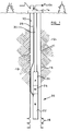
- Figure 1 is a cross-sectional, elevational view of an electric submergible pumping system (ESP) suspended within a subterranean wellbore.
- ESP electric submergible pumping system
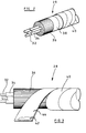
- Figure 2 is a cross-sectional, perspective view of one preferred embodiment of a multi-conductor electrical cable of the present invention.
- Figure 3 is a cross-sectional side view of an alternate preferred embodiment of a multi-conductor electrical cable of the present invention.
- the present invention comprises a multiconductor electrical cable for use in subterranean wellbores.
- the electrical cable of the present invention is made to withstand relatively high temperatures, high pressures and corrosive fluids encountered within subterranean wellbores; however, it should be understood that the electrical cable of the present invention can also be used in less difficult applications, such as surface power transmission, under water uses, and the like.
- high temperature means temperatures of greater than about 180 F and as high as about 500 F.
- high pressure means pressures as high as about 5,000 psi.
- corrosive fluids means liquids and gases which can cause degradation to insulating materials and/or corrosion to the electrical conductors, such as liquids and/or gases containing certain hydrocarbons, hydrogen sulfide, carbon dioxide, brine, and the like.
- Figure 1 shows a wellbore 10, used for recovering fluids such as water and/or hydrocarbons, that penetrates one or more subterranean earthen formations 12.
- the wellbore 10 includes a wellhead 14 removably connected to an upper portion of a production tubing and/or casing string 16, as is well known to those skilled in the art. If the casing string 16 extends across a fluid producing subterranean formation 12, then the casing string 16 can include at least one opening or perforations 18 for permitting fluids to enter the interior thereof.
- An electric submergible pumping system (“ESP”) 20 is shown suspended within the casing string 16, and generally includes an electric motor 22, an oil-filled motor protector 24, and a pump 26.
- ESP electric submergible pumping system
- the ESP 20 is shown in Figure 1 as deployed in a "conventional” configuration, with the motor 22 below the pump 26; however, it should be understood that the present invention can be used when the ESP 20 is in an "upside down” configuration, commonly known as a “bottom intake system.”
- the terms “upper” and “lower”, “above” and “below”, “uphole” and “downhole”, and “upwardly” and “downwardly” are relative terms to indicate position and direction of movement in easily recognized terms. Usually, these terms are relative to a line drawn from an upmost position at the surface of the earth to a point at the center of the earth, and would be appropriate for use in relatively straight, vertical wellbores. However, when the wellbore is highly deviated, such as from about 60 degrees from vertical, or horizontal, these terms do not make sense and therefore should not be taken as limitations. These terms are only used for ease of understanding as an indication of what the position or movement would be if taken within a vertical wellbore.
- a multiconductor cable 28 extends from a source of electrical power (not shown) at the earth's surface, through the casing 16, and is operatively connected to the motor 22.
- the cable 28 is preferably banded or strapped at intervals to a conduit 30, which is used to convey fluids from the pump 26 to the wellhead 14 at the earth's surface.
- the conduit 30 can be jointed tubing or coiled tubing, as is desired.
- Figure 2 shows one preferred embodiment of an electrical cable 28 of the present invention with three electrical conductors 32 in a round configuration.
- the cable 28 also can be formed to have a relatively flat configuration, with the electrical conductors 32 in parallel and side-by-side relationship.
- the electrical conductors 32 are single drawn wires of copper or copper alloys, or are formed from a twist of several wires.
- the conductors 32 are single drawn wires having a diameter or gauge thickness of from about 0.160" (6 AWG) to about 0.414" (2/0 AWG).
- each of the conductors 32 can have a relatively thin coating (not shown) of lead, tin or alloys thereof, hot dipped, heat extruded, or electroplated thereon.
- One or more ground wires may be included, as well as other wires, conductors, conduits, fibre optics, and the like, as may be used to transmit fluids and/or information and command signals through the power cable 28.
- At least one of the electrical conductors 32, and preferably all of the conductors 32, is sheathed in at least one layer of an insulating material 34, selected from the group consisting of polyolefin elastomers, ethylene propylene diene methylene, ethylene propylene rubber, polychloroprene, polyimide, fluroelastomers, polypropylene, polyethylene, polyether, and copolymers, mixtures, blends and alloys thereof.
- an insulating material 34 selected from the group consisting of polyolefin elastomers, ethylene propylene diene methylene, ethylene propylene rubber, polychloroprene, polyimide, fluroelastomers, polypropylene, polyethylene, polyether, and copolymers, mixtures, blends and alloys thereof.
- polyetherketone PEEK
- PEEK polyetheretherketone
- PEKK polyetherketoneketone
- PEKEKK polyetherketoneetherketoneketone
- the insulating material 34 is applied to the conductor 32 by spiral or longitudinal wrapping, or preferably by heat extrusion, as is well known to those skilled in the art.
- a fluid barrier (not shown) may be applied to the outer surface of the insulating material 34.
- the fluid barrier can be spirally wrapped or extruded non-metallic materials, such as polyethylene, polypropylene, polyvinyl fluoride, polyvinylidene fluoride, fluorinated ethylene propylene, polytetrafluoroethylene, or blends, mixtures or alloys thereof.
- the fluid barrier is preferably one or more extruded layers of a metal, such as lead, tin, and/or alloys thereof.
- a jacket 36 of elastomeric material is applied around the insulated conductors 32.
- the jacket 36 preferably comprises one or more extruded layers of nitrile rubber, ethylene propylene, ethylene propylene diene methylene terpolymer, polychloroprene, polyolefin elastomer, polyethylene, polypropylene, polyether, and copolymers, mixtures, blends and alloys thereof.
- the fluid barrier 38 comprises at least one layer of wrapped or extruded material selected from the group consisting essentially of polyethylene, polypropylene, polyvinyl fluoride, polyvinylidene fluoride, fluorinated ethylene propylene, polytetrafluoroethylene, and blends, mixtures and alloys thereof.
- the fluid barrier 38 is a helical wrap of TEFLON-brand fluoropolymer tape, having a thickness of application of from about 2 mils to about 6 mils.
- an outer protective armour 40 is applied over the fluid barrier 38 and the jacket 36, as is well known to those skilled in the art.
- the armour 40 is formed from a helical wrap of a band of metallic material, such as galvanized steel.
- Another important part of the present invention is the use of materials to prevent corrosion from degrading the ability of the armour 40 from restraining the swelling of the jacket 36.
- Materials used in one preferred embodiment of the present invention include one or more layers of non-metallic coatings, such as thermoplastic and/or thermoset materials.
- the resulting armour 40 is referred to as "coated armour.”
- the coated armour 40 of the present invention comprises a band of metallic material 42, such as steel or galvanized steel, and one or more layers of coating material 44, that is wrapped, sprayed, sintered, or extruded onto the metallic material 42.
- the preferred thickness of the coating 44 is from about 0.1 mils to about 70.0 mils.
- the coating material 44 can be one or more layers of one or more thermoplastic materials.
- Preferred thermoplastic materials are acrylonitrile-butadiene-styrene (ABS) copolymers, acetals, tetrafluroethylene-propylene copolymers, hexafluropropylene-vinylidene copolymers, polyamides, arimids, polyaryl sulfones, polyaryl ethers, polyesters, polyether sulfones, polyamides, polyamide-imides, polyphenylene sulfide, poly sulfones, polyetherketones, polyetheretherketones, polyetherketonesetheretherketones, polyaryletherketones, polyethylenes, polypropylenes, epoxies, and copolymers, mixtures, blends and alloys thereof.
- ABS acrylonitrile-butadiene-styrene
- thermoset materials are copolymers of acrylonitrile and butadiene, saturated copolymers of acrylonitrile and butadiene, fluroelastomers, polychloroprenes, and copolymers, mixtures, blends and alloys thereof.
- the present invention is a multiconductor electrical cable for use in a subterranean wellbore that has increased resistance to swelling by preventing hydrocarbons or water from contacting the jacket of elastomeric material, and/or by preventing corrosion of the metallic outer protective armour so that any swelling will be contained.
Landscapes
- Physics & Mathematics (AREA)
- Spectroscopy & Molecular Physics (AREA)
- Insulated Conductors (AREA)
Applications Claiming Priority (2)
| Application Number | Priority Date | Filing Date | Title |
|---|---|---|---|
| US99437197A | 1997-12-19 | 1997-12-19 | |
| US994371 | 1997-12-19 |
Publications (2)
| Publication Number | Publication Date |
|---|---|
| EP0924711A2 true EP0924711A2 (fr) | 1999-06-23 |
| EP0924711A3 EP0924711A3 (fr) | 1999-07-07 |
Family
ID=25540588
Family Applications (1)
| Application Number | Title | Priority Date | Filing Date |
|---|---|---|---|
| EP98305946A Withdrawn EP0924711A3 (fr) | 1997-12-19 | 1998-07-27 | Câble électrique multiconducteur |
Country Status (3)
| Country | Link |
|---|---|
| EP (1) | EP0924711A3 (fr) |
| CA (1) | CA2255482A1 (fr) |
| NO (1) | NO985776L (fr) |
Cited By (6)
| Publication number | Priority date | Publication date | Assignee | Title |
|---|---|---|---|---|
| EP2204823A1 (fr) * | 2009-01-06 | 2010-07-07 | BP Exploration Operating Company Limited | Câble |
| WO2011144933A1 (fr) * | 2010-05-18 | 2011-11-24 | Tyco Electronics Uk Ltd | Bande isolante à haute température et fil ou câble revêtu par celle-ci |
| WO2015100342A1 (fr) * | 2013-12-23 | 2015-07-02 | General Cable Technologies Corporation | Câble à haute visibilité |
| WO2017080621A1 (fr) * | 2015-11-13 | 2017-05-18 | Prysmian S.P.A. | Câble électrique à armure résistant à la corrosion |
| CN106920591A (zh) * | 2017-05-11 | 2017-07-04 | 南京全信传输科技股份有限公司 | 核动力装备用低烟无卤阻燃交联橡皮绝缘耐辐照电缆 |
| US11072999B2 (en) | 2016-12-30 | 2021-07-27 | Metrol Technology Ltd. | Downhole energy harvesting |
Family Cites Families (5)
| Publication number | Priority date | Publication date | Assignee | Title |
|---|---|---|---|---|
| US4214693A (en) * | 1978-05-30 | 1980-07-29 | Smith William D | Method of making wireline apparatus for use in earth boreholes |
| US4658089A (en) * | 1985-05-28 | 1987-04-14 | Hughes Tool Company | Electrical cable with fabric layer |
| US5146982A (en) * | 1991-03-28 | 1992-09-15 | Camco International Inc. | Coil tubing electrical cable for well pumping system |
| FR2709592B1 (fr) * | 1993-09-02 | 1996-02-02 | Pirelli Cables | Câble résistant aux agressions chimiques. |
| US5426264A (en) * | 1994-01-18 | 1995-06-20 | Baker Hughes Incorporated | Cross-linked polyethylene cable insulation |
-
1998
- 1998-07-27 EP EP98305946A patent/EP0924711A3/fr not_active Withdrawn
- 1998-12-10 NO NO985776A patent/NO985776L/no not_active Application Discontinuation
- 1998-12-10 CA CA002255482A patent/CA2255482A1/fr not_active Abandoned
Cited By (10)
| Publication number | Priority date | Publication date | Assignee | Title |
|---|---|---|---|---|
| EP2204823A1 (fr) * | 2009-01-06 | 2010-07-07 | BP Exploration Operating Company Limited | Câble |
| WO2011144933A1 (fr) * | 2010-05-18 | 2011-11-24 | Tyco Electronics Uk Ltd | Bande isolante à haute température et fil ou câble revêtu par celle-ci |
| CN102883882A (zh) * | 2010-05-18 | 2013-01-16 | 泰科电子英国有限公司 | 高温绝缘带和用其覆套的电线或电缆 |
| WO2015100342A1 (fr) * | 2013-12-23 | 2015-07-02 | General Cable Technologies Corporation | Câble à haute visibilité |
| US10147520B2 (en) | 2013-12-23 | 2018-12-04 | General Cable Technologies Corporation | High visibility cable |
| WO2017080621A1 (fr) * | 2015-11-13 | 2017-05-18 | Prysmian S.P.A. | Câble électrique à armure résistant à la corrosion |
| US10692626B2 (en) | 2015-11-13 | 2020-06-23 | Prysmian S.P.A. | Electric cable with corrosion resistant armor |
| US11072999B2 (en) | 2016-12-30 | 2021-07-27 | Metrol Technology Ltd. | Downhole energy harvesting |
| EP3563028B1 (fr) * | 2016-12-30 | 2022-08-17 | Metrol Technology Ltd | Dispositif de récupération d'énergie en fond de trou |
| CN106920591A (zh) * | 2017-05-11 | 2017-07-04 | 南京全信传输科技股份有限公司 | 核动力装备用低烟无卤阻燃交联橡皮绝缘耐辐照电缆 |
Also Published As
| Publication number | Publication date |
|---|---|
| NO985776L (no) | 1999-06-21 |
| CA2255482A1 (fr) | 1999-06-19 |
| EP0924711A3 (fr) | 1999-07-07 |
| NO985776D0 (no) | 1998-12-10 |
Similar Documents
| Publication | Publication Date | Title |
|---|---|---|
| CA2241639C (fr) | Armure non metallique de cable electrique | |
| US4665281A (en) | Flexible tubing cable system | |
| US6555752B2 (en) | Corrosion-resistant submersible pump electric cable | |
| EP1854107B1 (fr) | Cables electriques de puits de forage ameliores | |
| CA2417067C (fr) | Cable electrique et methode connexe | |
| CA2135380C (fr) | Cable a armure double avec ligne auxiliaire | |
| US4515993A (en) | Low profile submersible electrical cable | |
| US7763802B2 (en) | Electrical cable | |
| EP0670577A1 (fr) | Isolation pour câble à base de polyéthylène réticulé | |
| US20140102749A1 (en) | Electric Submersible Pump Cables for Harsh Environments | |
| US20140238718A1 (en) | Protective armor for cabling | |
| WO1999048111A1 (fr) | Cable de manipulation conducteur | |
| GB2115972A (en) | Oil well cable | |
| CA2599836C (fr) | Tuyau souple d'application pour hydrocarbures | |
| US20090067776A1 (en) | Optical fibers | |
| EP0924711A2 (fr) | Câble électrique multiconducteur | |
| US4214693A (en) | Method of making wireline apparatus for use in earth boreholes | |
| EP3045794B1 (fr) | Câble de fond de trou avec un tube non métallique intégré | |
| US4137762A (en) | Wireline apparatus for use in earth boreholes | |
| WO2016148673A1 (fr) | Câble de puissance haute température résistant à la pénétration de fluides | |
| EP0930622A1 (fr) | Moteur submersible électrique avec protection interne contre la corrosion | |
| EP0887807A1 (fr) | Câble électrique multibrin | |
| US20010050111A1 (en) | Flat pack encapsulated tubing package for well control cable | |
| EP0907188A1 (fr) | Câble électrique multiconducteur | |
| CA2238120A1 (fr) | Cable electrique multiconducteur |
Legal Events
| Date | Code | Title | Description |
|---|---|---|---|
| PUAI | Public reference made under article 153(3) epc to a published international application that has entered the european phase |
Free format text: ORIGINAL CODE: 0009012 |
|
| PUAL | Search report despatched |
Free format text: ORIGINAL CODE: 0009013 |
|
| AK | Designated contracting states |
Kind code of ref document: A2 Designated state(s): DE FR GB |
|
| AX | Request for extension of the european patent |
Free format text: AL;LT;LV;MK;RO;SI |
|
| AK | Designated contracting states |
Kind code of ref document: A3 Designated state(s): AT BE CH CY DE DK ES FI FR GB GR IE IT LI LU MC NL PT SE |
|
| AX | Request for extension of the european patent |
Free format text: AL;LT;LV;MK;RO;SI |
|
| 17P | Request for examination filed |
Effective date: 19990812 |
|
| AKX | Designation fees paid |
Free format text: DE FR GB |
|
| STAA | Information on the status of an ep patent application or granted ep patent |
Free format text: STATUS: THE APPLICATION HAS BEEN WITHDRAWN |
|
| 18W | Application withdrawn |
Withdrawal date: 20000428 |