EP0924728A2 - Hoghspannungsschalter für hohen Nennstrom - Google Patents
Hoghspannungsschalter für hohen Nennstrom Download PDFInfo
- Publication number
- EP0924728A2 EP0924728A2 EP98204267A EP98204267A EP0924728A2 EP 0924728 A2 EP0924728 A2 EP 0924728A2 EP 98204267 A EP98204267 A EP 98204267A EP 98204267 A EP98204267 A EP 98204267A EP 0924728 A2 EP0924728 A2 EP 0924728A2
- Authority
- EP
- European Patent Office
- Prior art keywords
- circuit breaker
- spring
- insulator
- opening
- actuating
- Prior art date
- Legal status (The legal status is an assumption and is not a legal conclusion. Google has not performed a legal analysis and makes no representation as to the accuracy of the status listed.)
- Granted
Links
Images


Classifications
-
- H—ELECTRICITY
- H01—ELECTRIC ELEMENTS
- H01H—ELECTRIC SWITCHES; RELAYS; SELECTORS; EMERGENCY PROTECTIVE DEVICES
- H01H33/00—High-tension or heavy-current switches with arc-extinguishing or arc-preventing means
- H01H33/02—Details
- H01H33/42—Driving mechanisms
Definitions
- the present invention relates to a circuit breaker for high-voltage currents.
- circuit breakers for high-voltage currents must be actuated quickly and promptly.
- the use of direct actuators of the electromechanical type would entail devices of unacceptable size; accordingly, systems for accumulating mechanical energy are generally used. Energy accumulation occurs over a few hundred seconds. Energy is then used and delivered over a few tens of milliseconds.
- Main aim of the present invention is to provide a circuit breaker for high-voltage currents which allows to eliminate the complicated stroke multiplying mechanisms required to transmit motion to the movable parts of the pole of the circuit breaker.
- an object of the present invention is to provide a circuit breaker for high-voltage currents which allows to reduce the energy required to transmit motion to the movable contacts of said circuit breaker so as to improve its performance in terms of speed and promptness of intervention.
- Another object of the present invention is to provide a circuit breaker for high-voltage currents with a pole having a smaller number of components, a reduced weight and, insulation levels being equal, smaller size.
- a circuit breaker for high-voltage currents which comprises a vertical rod-like insulator, at least one arcing chamber arranged inside said insulator and containing fixed contacts and movable contacts, said movable contacts being connected to actuation means for opening and closing the circuit breaker, characterized in that it comprises first and second elastic means, for opening and for closing respectively, which are made of insulating material and are arranged inside said insulator, and means for actuating the circuit breaker which are coupled to the base of said insulator.
- the circuit breaker according to the invention comprises a pole which is constituted by an insulator 4, by fixed contacts 1 and by movable contacts 2.
- An electric power tap 3 protrudes from the insulator and supports a movable contact holder 10 by means of an intermediate flange 11.
- elastic means which are conveniently constituted by two springs 6 and 7, respectively for opening and for closure, which are made of insulating material.
- the opening spring 6 one end is connected to a movable drive rod 5, which is also made of insulating material and which, by actuating the movable contacts 2, allows to open and close the circuit breaker, and the other end is fixed to the flange 11.
- the closure spring 7 one end is coupled to sliding support means 12 which are connected, by means of a tube 13, to circuit breaker actuation means 8, and the other end is connected to the flange 11.
- the tube 13 is coupled to the drive rod 5 through engagement means 16 which are fixed to the tube 13 and have a pawl that engages a slot formed in the rod 5.
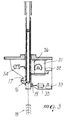
- the circuit breaker actuation means 8 comprise a gearmotor 31, a worm screw 36, two electrical engagement devices 34 and 35, and two engagement means 19 and 20 and are directly connected to the flange 9 of the insulator 4 by means of the flange 14. In this manner they are rigidly coupled to the base of the insulator 4.
- the gearmotor 31 starts by means of the stroke limiter switch 32 and can reload the closure spring 7 which, at the end of its loading, engages the engagement means 19; the wheel of the gearmotor disengages from the worm screw 36 and the gearmotor stops due to the stroke limiter 33.
- Opening of the contacts which can be performed if necessary also during the reloading of the closure spring, occurs by energizing the electromagnet 34. In this manner, the engagement means 20 are released and the opening spring 6, as it is released, pushes down the rod 5, which opens the contacts.
- circuit breaker according to the invention it is possible to perform quick opening-closure-opening with the following sequence.
- the engagement means 19 are released and the circuit breaker, as described above, closes. In this situation, the opening spring is loaded and the insulating rod 5 is engaged with the engagement means 20.
- the circuit breaker By re-energizing the electromagnet 34, the circuit breaker reopens.
- Auxiliary contacts 18 of the insulator are switched at each actuation.
- FIG. 4 A second embodiment of the circuit breaker according to the invention is now described with reference to Figure 4.
- the opening and closure springs now designated by the reference numerals 3 and 4 are contained in the insulator 5 of the pole of the circuit breaker and are made of insulating material.
- one end is fixed to a flange 30 and the other end is fixed to an insulating rod 50 which, by actuating the movable contacts 2, allows to open and close the circuit breaker.
- the closure spring 4 one end is fixed to the flange 30, while the other end is connected to a system constituted by a linkage 61 and a lever 62.
- the actuating means comprise two electric engagement devices 39 and 41 and a gearmotor 42.
- the closure spring 4 is loaded (compressed) and the opening spring 3 is released, energization of the electrical engagement device 40 releases the kinematic chain 62, 61 and 4.
- the closure spring 4 is released and, by elongating, pushes the lever 62 which, by means of the linkage 63 and the levers 64 and 65, moves upward the rod 50, which causes the closure of the contacts and the loading (by compression) of the opening spring 3.
- the lever 64 engages the electrical engagement device 41; at the same time, the lever 66 disengages the lever 64 from the lever 62, making the opening mechanism independent of the closure mechanism.
- the gearmotor 42 can thus reload the closure spring 4.
- the spring 4 engages the electrical engagement device 40 and the gearmotor 42 disengages from the lever 62 by means of a disengagement device 43.
- the opening of the contacts which can be performed if necessary also during reloading of the closure spring, occurs by energizing the electrical engagement device 41, which releases the lever 64.
- the opening spring 3 is no longer retained and is released, pushing the rod 50, which opens the contacts.
- circuit breaker according to the invention is the fact that the insulator of the pole is monolithically made of composite material coated with polymeric material. Accordingly, this allows to reduce the number of components of the pole, its weight and, insulation levels being equal, its size.
- circuit breaker thus conceived is susceptible of numerous modifications and variations, all of which are within the scope of the inventive concept; all the details may also be replaced with other technically equivalent elements.
- the materials and the dimensions may be any according to requirements and to the state of the art.
Landscapes
- Driving Mechanisms And Operating Circuits Of Arc-Extinguishing High-Tension Switches (AREA)
- Circuit Arrangements For Discharge Lamps (AREA)
- Oscillators With Electromechanical Resonators (AREA)
- Relay Circuits (AREA)
- Circuit Breakers (AREA)
Applications Claiming Priority (2)
| Application Number | Priority Date | Filing Date | Title |
|---|---|---|---|
| ITMI972795 | 1997-12-17 | ||
| ITMI972795 IT1296880B1 (it) | 1997-12-17 | 1997-12-17 | Interruttore per correnti ad alta tensione |
Publications (3)
| Publication Number | Publication Date |
|---|---|
| EP0924728A2 true EP0924728A2 (de) | 1999-06-23 |
| EP0924728A3 EP0924728A3 (de) | 2001-03-28 |
| EP0924728B1 EP0924728B1 (de) | 2007-01-24 |
Family
ID=11378388
Family Applications (1)
| Application Number | Title | Priority Date | Filing Date |
|---|---|---|---|
| EP19980204267 Expired - Lifetime EP0924728B1 (de) | 1997-12-17 | 1998-12-16 | Hochspannungsschalter für hohen Nennstrom |
Country Status (3)
| Country | Link |
|---|---|
| EP (1) | EP0924728B1 (de) |
| DE (1) | DE69836952T2 (de) |
| IT (1) | IT1296880B1 (de) |
Cited By (4)
| Publication number | Priority date | Publication date | Assignee | Title |
|---|---|---|---|---|
| DE102015208268A1 (de) * | 2015-05-05 | 2016-11-10 | Siemens Aktiengesellschaft | Elektrisches Schaltgerät und entsprechende Schaltungsanlage |
| WO2016190827A1 (en) * | 2015-05-28 | 2016-12-01 | Sfa Elektromekani̇k Elektri̇k Sanayi̇ Ve Ti̇caret Anoni̇m Şi̇rketi̇ | Switching mechanism comprising the combination of breaker, separator and grounding apparatus |
| WO2017050561A1 (de) * | 2015-09-25 | 2017-03-30 | Siemens Aktiengesellschaft | Antrieb und verfahren zum antreiben eines leistungsschalters |
| CN110462776A (zh) * | 2017-03-28 | 2019-11-15 | Ls产电株式会社 | 高速开关 |
Family Cites Families (5)
| Publication number | Priority date | Publication date | Assignee | Title |
|---|---|---|---|---|
| CH660256A5 (de) * | 1983-01-25 | 1987-03-31 | Sprecher Energie Ag | Antriebsanordnung fuer einen hochspannungsschalter. |
| FR2589001A1 (fr) * | 1985-10-23 | 1987-04-24 | Alsthom | Dispositif de manoeuvre d'un disjoncteur et disjoncteur muni de ce dispositif |
| US5508487A (en) * | 1994-03-30 | 1996-04-16 | Abb Power T&D Company Inc. | High voltage circuit interrupting device operating mechanism including trip latch assembly |
| US5504289A (en) * | 1994-03-30 | 1996-04-02 | Abb Power T&D Company Inc. | Circuit switching mechanism and charging system therefor |
| IT1282078B1 (it) * | 1996-02-02 | 1998-03-09 | Abb Research Ltd | Interruttore per corrente ad alta tensione |
-
1997
- 1997-12-17 IT ITMI972795 patent/IT1296880B1/it active IP Right Grant
-
1998
- 1998-12-16 DE DE69836952T patent/DE69836952T2/de not_active Expired - Fee Related
- 1998-12-16 EP EP19980204267 patent/EP0924728B1/de not_active Expired - Lifetime
Cited By (7)
| Publication number | Priority date | Publication date | Assignee | Title |
|---|---|---|---|---|
| DE102015208268A1 (de) * | 2015-05-05 | 2016-11-10 | Siemens Aktiengesellschaft | Elektrisches Schaltgerät und entsprechende Schaltungsanlage |
| WO2016190827A1 (en) * | 2015-05-28 | 2016-12-01 | Sfa Elektromekani̇k Elektri̇k Sanayi̇ Ve Ti̇caret Anoni̇m Şi̇rketi̇ | Switching mechanism comprising the combination of breaker, separator and grounding apparatus |
| WO2017050561A1 (de) * | 2015-09-25 | 2017-03-30 | Siemens Aktiengesellschaft | Antrieb und verfahren zum antreiben eines leistungsschalters |
| CN110462776A (zh) * | 2017-03-28 | 2019-11-15 | Ls产电株式会社 | 高速开关 |
| EP3605576A4 (de) * | 2017-03-28 | 2020-04-08 | LSIS Co., Ltd. | Hochgeschwindigkeitsschalter |
| US10818454B2 (en) | 2017-03-28 | 2020-10-27 | Lsis Co., Ltd. | High speed switch |
| CN110462776B (zh) * | 2017-03-28 | 2022-04-29 | Ls产电株式会社 | 高速开关 |
Also Published As
| Publication number | Publication date |
|---|---|
| ITMI972795A1 (it) | 1999-06-17 |
| EP0924728B1 (de) | 2007-01-24 |
| DE69836952T2 (de) | 2007-11-08 |
| DE69836952D1 (de) | 2007-03-15 |
| IT1296880B1 (it) | 1999-08-02 |
| EP0924728A3 (de) | 2001-03-28 |
Similar Documents
| Publication | Publication Date | Title |
|---|---|---|
| US5504290A (en) | Remote controlled circuit breaker with recharging cam | |
| US5604340A (en) | Gas insulated switchgear insertion resistor and main contacts operating mechanism having time delay feature | |
| US4049936A (en) | Quick-acting movable operating-column tripping device | |
| US7115828B2 (en) | Internally switched electric power interrupter | |
| US20010017288A1 (en) | Electromagnet and operating mechanism of switch therewith | |
| CN101425422B (zh) | 气体绝缘断路器 | |
| US5859398A (en) | Sequential isolating circuit breaker and actuator | |
| US9184014B2 (en) | Electrical operator for circuit breaker and method thereof | |
| EP0924728B1 (de) | Hochspannungsschalter für hohen Nennstrom | |
| RU2613329C2 (ru) | Устройство защитного отключения коммутационного прибора | |
| US4114003A (en) | Quick-acting movable operating-column tripping device | |
| US3234803A (en) | Spring operator means | |
| AU2003261668B2 (en) | Drive mechanism for switching installation and method for operating it | |
| US8183486B2 (en) | Spring arrangement for spring drive unit and spring drive unit comprising spring arrangement | |
| US20120168293A1 (en) | Spring housing unit connected with spring actuator for switchgear | |
| US7557682B2 (en) | Inertial solenoid delay for the opening of medium voltage circuit breakers | |
| RU2237309C1 (ru) | Вакуумный выключатель внутренней установки | |
| US20240312751A1 (en) | Electric switching device with improved actuation mechanism | |
| RU2040817C1 (ru) | Высоковольтный вакуумный выключатель | |
| US4204103A (en) | Driving apparatus for electric power circuit breakers | |
| RU2134464C1 (ru) | Привод выключателя нагрузки | |
| CN119852126B (zh) | 基于磁控操动机构的直动式互锁装置 | |
| EP4521433A1 (de) | Schwungrad mit einer schalteinrichtung zur regelung einer einschaltgeschwindigkeit von schaltkontakten eines leistungsschalters | |
| SU1210152A1 (ru) | Вакуумный выключатель | |
| RU2040815C1 (ru) | Вакуумный выключатель |
Legal Events
| Date | Code | Title | Description |
|---|---|---|---|
| PUAI | Public reference made under article 153(3) epc to a published international application that has entered the european phase |
Free format text: ORIGINAL CODE: 0009012 |
|
| AK | Designated contracting states |
Kind code of ref document: A2 Designated state(s): CH DE FR GB IT LI |
|
| AX | Request for extension of the european patent |
Free format text: AL;LT;LV;MK;RO;SI |
|
| PUAL | Search report despatched |
Free format text: ORIGINAL CODE: 0009013 |
|
| AK | Designated contracting states |
Kind code of ref document: A3 Designated state(s): AT BE CH CY DE DK ES FI FR GB GR IE IT LI LU MC NL PT SE |
|
| AX | Request for extension of the european patent |
Free format text: AL;LT;LV;MK;RO;SI |
|
| RIC1 | Information provided on ipc code assigned before grant |
Free format text: 7H 01H 33/42 A, 7H 01H 33/40 B |
|
| 17P | Request for examination filed |
Effective date: 20010920 |
|
| AKX | Designation fees paid |
Free format text: CH DE FR GB IT LI |
|
| RAP1 | Party data changed (applicant data changed or rights of an application transferred) |
Owner name: ABB TRASMISSIONE & DISTRIBUZIONE SPA |
|
| GRAP | Despatch of communication of intention to grant a patent |
Free format text: ORIGINAL CODE: EPIDOSNIGR1 |
|
| GRAS | Grant fee paid |
Free format text: ORIGINAL CODE: EPIDOSNIGR3 |
|
| GRAA | (expected) grant |
Free format text: ORIGINAL CODE: 0009210 |
|
| RAP1 | Party data changed (applicant data changed or rights of an application transferred) |
Owner name: ABB POWER TECHNOLOGIES S.P.A. |
|
| AK | Designated contracting states |
Kind code of ref document: B1 Designated state(s): CH DE FR GB IT LI |
|
| PG25 | Lapsed in a contracting state [announced via postgrant information from national office to epo] |
Ref country code: LI Free format text: LAPSE BECAUSE OF FAILURE TO SUBMIT A TRANSLATION OF THE DESCRIPTION OR TO PAY THE FEE WITHIN THE PRESCRIBED TIME-LIMIT Effective date: 20070124 Ref country code: CH Free format text: LAPSE BECAUSE OF FAILURE TO SUBMIT A TRANSLATION OF THE DESCRIPTION OR TO PAY THE FEE WITHIN THE PRESCRIBED TIME-LIMIT Effective date: 20070124 |
|
| REG | Reference to a national code |
Ref country code: GB Ref legal event code: FG4D |
|
| REG | Reference to a national code |
Ref country code: CH Ref legal event code: EP |
|
| REF | Corresponds to: |
Ref document number: 69836952 Country of ref document: DE Date of ref document: 20070315 Kind code of ref document: P |
|
| ET | Fr: translation filed | ||
| REG | Reference to a national code |
Ref country code: CH Ref legal event code: PL |
|
| PLBE | No opposition filed within time limit |
Free format text: ORIGINAL CODE: 0009261 |
|
| STAA | Information on the status of an ep patent application or granted ep patent |
Free format text: STATUS: NO OPPOSITION FILED WITHIN TIME LIMIT |
|
| 26N | No opposition filed |
Effective date: 20071025 |
|
| PG25 | Lapsed in a contracting state [announced via postgrant information from national office to epo] |
Ref country code: IT Free format text: LAPSE BECAUSE OF FAILURE TO SUBMIT A TRANSLATION OF THE DESCRIPTION OR TO PAY THE FEE WITHIN THE PRESCRIBED TIME-LIMIT Effective date: 20070124 |
|
| GBPC | Gb: european patent ceased through non-payment of renewal fee |
Effective date: 20071216 |
|
| PG25 | Lapsed in a contracting state [announced via postgrant information from national office to epo] |
Ref country code: DE Free format text: LAPSE BECAUSE OF NON-PAYMENT OF DUE FEES Effective date: 20080701 |
|
| REG | Reference to a national code |
Ref country code: FR Ref legal event code: ST Effective date: 20081020 |
|
| PG25 | Lapsed in a contracting state [announced via postgrant information from national office to epo] |
Ref country code: GB Free format text: LAPSE BECAUSE OF NON-PAYMENT OF DUE FEES Effective date: 20071216 |
|
| PG25 | Lapsed in a contracting state [announced via postgrant information from national office to epo] |
Ref country code: FR Free format text: LAPSE BECAUSE OF NON-PAYMENT OF DUE FEES Effective date: 20071231 |