EP0924731A2 - Disjoncteur avec logement pour accessoire avec couvercle et accessoire avec verrouillage et tirette - Google Patents
Disjoncteur avec logement pour accessoire avec couvercle et accessoire avec verrouillage et tirette Download PDFInfo
- Publication number
- EP0924731A2 EP0924731A2 EP98123905A EP98123905A EP0924731A2 EP 0924731 A2 EP0924731 A2 EP 0924731A2 EP 98123905 A EP98123905 A EP 98123905A EP 98123905 A EP98123905 A EP 98123905A EP 0924731 A2 EP0924731 A2 EP 0924731A2
- Authority
- EP
- European Patent Office
- Prior art keywords
- module
- disposed
- recess
- combination
- locking
- Prior art date
- Legal status (The legal status is an assumption and is not a legal conclusion. Google has not performed a legal analysis and makes no representation as to the accuracy of the status listed.)
- Granted
Links
Images




Classifications
-
- H—ELECTRICITY
- H01—ELECTRIC ELEMENTS
- H01H—ELECTRIC SWITCHES; RELAYS; SELECTORS; EMERGENCY PROTECTIVE DEVICES
- H01H71/00—Details of the protective switches or relays covered by groups H01H73/00 - H01H83/00
- H01H71/02—Housings; Casings; Bases; Mountings
- H01H71/0207—Mounting or assembling the different parts of the circuit breaker
- H01H71/0228—Mounting or assembling the different parts of the circuit breaker having provisions for interchangeable or replaceable parts
Definitions
- circuit interrupters generally and more particularly to accessory modules.
- the present invention provides an improvement over the invention of U.S. patent 4,503,408 issued March 5, 1985 to Mrenna et al entitled "Molded Case Circuit Breaker Apparatus Having Trip Bar With Flexible Armor Interconnection" which is assigned at this time to the assignee of the present application and which is incorporated by reference herein.
- Accessories for molded case circuit breakers have been known for a long time. Generally in the past the accessories have been mounted externally of the internal portion of the circuit breaker. An example of such an accessory is found in U.S.
- an electrical circuit interrupter has a housing base having a first locking opening therein.
- a module useful for performing a desirable function is deposed within that housing base.
- the module has a second locking device which is complimentary with the first locking opening.
- the first and second locking devices cooperate with each other to secure the module to the housing base.
- the circuit breaker also has an operating mechanism and first and second main contacts disposed therein for opening and closing.
- that housing base has a recess therein, the recess having a locking opening therein.
- the aforementioned module has a locking protrusion which is complimentary with the locking opening.
- the other parts of the circuit breaker interrupter are basically the same.
- the locking protrusion is flexible and may contain a longitudinal slot to accommodate flexion.
- the module may have a tab attached thereto which may be tugged upon to pull the module from the case when it is desired to remove the module.
- a secondary cover is placed over the module once it is locked in place within the housing base.
- Molded case circuit breaker 10 includes a lower base portion 14 mechanically interconnected with a primary cover 18. Disposed on top of the primary cover 18 is an auxiliary or secondary cover 22.
- the secondary cover 22 may be removed from the circuit breaker rendering some internal portions of the circuit breaker available for maintenance and the like without disassembling the entire circuit breaker.
- the secondary cover 22 may shield auxiliary devices or modules such as under-voltage relays, bell alarms, shunt trips and auxiliary switches. Holes or openings 26 are provided in the secondary cover 22 for accepting screws for fastening the auxiliary or secondary cover 22 to the primary cover 18.
- Additional holes 30 which feed through the auxiliary cover 22, the primary cover 18 and the base 14 are provided for bolting the entire circuit breaker assembly onto a wall, into a DIN rail back panel or into a load center or the like.
- the primary cover has a recess 18 therein for receiving a drop-in module as will be described hereinafter.
- the auxiliary cover 22 includes an auxiliary cover handle opening 34.
- the primary or main cover 18 includes a primary cover handle opening 38.
- There is provided a handle 42 which protrudes through the aforementioned auxiliary cover handle opening 34 and the primary cover handle opening 38.
- the handle 42 is utilized in the normal manner to open and close the contacts of the circuit breaker manually and to reset the circuit breaker when it has been tripped.
- circuit breaker It may also be provided as an indication of the status of the circuit breaker, that is whether the circuit breaker is ON, OFF or TRIPPED disposition.
- three load conductor openings 46 which shield and protect load terminals 50 (not shown).
- the circuit breaker depicted is a three-phase circuit breaker. However, the invention is not limited to three-phase operation.
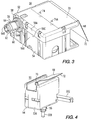
- Drop-in module 50 may comprise two or more snap together portions 52 and 54.
- the bottom most portion of modular element 50 comprises a locking protrusion 56.
- Locking protrusion 56 may include a widened base 58 which is integral with the bottom portions 59A and 59B of the sections 52 and 54 respectively.
- the locking protrusion 56 is made flexible to accommodate insertion into a locking opening as will be described hereinafter. The flexibility may be provided by the inherit resiliency of the material of the protrusion 56 and one or more longitudinal slots 64 in the protrusion 56.
- there are four non-limiting slots 64 two of which 64A and 64B, roughly align with the dividing line region 59C between the case portion 52 and the case portion 54.
- half of the locking protrusion 56 may be constructed when the module or case portion 52 is being constructed and the other half may be constructed as part of the construction of the modular case portion 54.
- a pull tab 68 having a region 70 for attachment to the module 50 and a region 72 which may be tugged upon or pulled in order to remove the shunt trip case or module 50 from its locked-in position in the circuit breaker in a manner which will be described hereinafter.
- Pull tab 68 may be attached to the module 50 by way of holes or opening 74 in region 70 through which protrusions 74A in the section 52 of the module 50 may protrude.
- the module 50 represents a case for a shunt trip apparatus of the kind described in co-pending application serial no 08/864,104 (96-PDC-547).
- the combination auxiliary switch bell alarm module 90 is depicted.
- it may comprise two or more joinable sections 326 and 94 which are joined together to form the module 90 and which are lockably inserted into the circuit breaker 10 a manner which will be described hereinafter.
- a pull tab 68 similar to that shown with respect to Figure 3, having two sections 70 and 72 is also depicted.
- Pull tab 68 may be conveniently attached to the case 90 in a manner similar to that shown in Figure 3.
- the locking protrusion 56 is shown depending from the bottom of the case of the auxiliary module 90.
- locking protrusion 56 may be exactly the same as shown with respect to the module 50 shown in Figure 3.
- auxiliary switch rider 328 Protruding there through is an auxiliary switch rider 328 which may move up and down in a manner to be described with respect to the description associated with Figure 6.
- a cradle follower 332 which protrudes at a right angle relative to the cam follower 328 from the other side of the enclosure 326 interacts with a bell alarm device 324 as shown in Figure 4.
- the case module 90 is pulled upwardly as a result of tugging on its tab 68 so that that the flexible protrusion 56 flexes inwardly at the slots or opening 64 to disengage it from the locking opening 100.
- the tabs of the locking member 56 are depressed or flexed inwardly during the insertion process so that the enlarged region 60 is made circumferentially smaller so that the locking opening 100 may capture the locking protrusion 56 between its enlarged portion 60 and its base portion 68 such as is shown in Figure 3 for example.
- auxiliary switch 320 and a bell alarm 324 are shown.
- the module 90 shown partially broken away inside of which the auxiliary switch 320 is shown.
- a pair of auxiliary switches 320 or a pair of bell alarms 324 may be disposed within the enclosure 326 or the disposition of the auxiliary switch 320 and bell alarm 324 may be reversed.
- the bell alarm 324 is disposed in the same housing 326 on the other side of an insulating auxiliary wall 325.
- Switch 320 has protruding from the bottom thereof the axially movable cam follower 328 which follows the upper cam surface 100A of a cross bar assembly 100 of the circuit breaker.
- the assembly 100 When the contacts of the circuit breaker are closed, the assembly 100 is in one disposition and when the contacts are open, the assembly is in a second disposition.
- the difference between the dispositions is tracked by the cam follower 328.
- the cam follower 328 interconnects with contacts (not shown) in the auxiliary switch 320 such that normally open contact 320A is in one disposition when the contacts are open and in the opposite disposition when the contacts are closed.
- the complimentary set of contacts 320B are in the opposite dispositions at these times.
- Appropriate power for causing certain desirable functions as a result of the status and/or change of status of the auxiliary switch 320 may be provided by a set of wires.
- cradle follower 332 which protrudes at a right angle relative to the cam follower 328 from the other side of the module 90 for interacting with or actuating the bell alarm 324.
- This arrangement may be used to alert operating personnel that the circuit breaker has tripped and the contacts are opened.
- Both the auxiliary switch 320 and alarm 324 are contained within one enclosure 326 - 94 (see Fig 4) which is independently removable from the circuit breaker mechanism without complete disassembly thereof by removal of the aforementioned secondary or auxiliary cover 22 (not shown) and subsequent removal of the module 90. Insertion of the module 90 may occur in a similar but reverse manner.
- modules 50and 90 may be utilized to-show casings for shunt trip apparatus, auxiliary switches and bell alarms, such cases may be also be used for under voltage relays and the like.
- apparatus which may be disposed within the case depending upon the desirability of the electrical function to be performed and the availability of space.
- the apparatus taught with respect to the embodiments of this invention has many advantages.
- One advantage lies in the fact that the locking arrangement shown herein provides a secure way to affix or maintain an auxiliary module or the like within a circuit breaker case so as to prevent ejection therefrom by the build up of hot gases which may permeate the circuit breaker case under pressure during a circuit interrupting operation.
- the gases which are permitted to reach the accessories due to the conflicting need to seal the breaker yet still permit access to the operating mechanism to actuate the accessories, could propel the module outwardly against the secondary or auxiliary cover 22 shown in Figure 1, thus perhaps causing damage to the cover or destroying its structural integrity.
Landscapes
- Switch Cases, Indication, And Locking (AREA)
- Breakers (AREA)
Applications Claiming Priority (2)
| Application Number | Priority Date | Filing Date | Title |
|---|---|---|---|
| US994633 | 1997-12-19 | ||
| US08/994,633 US5921380A (en) | 1997-12-19 | 1997-12-19 | Circuit interrupter with covered accessory case with accessory having lock-in feature and pull tab |
Publications (3)
| Publication Number | Publication Date |
|---|---|
| EP0924731A2 true EP0924731A2 (fr) | 1999-06-23 |
| EP0924731A3 EP0924731A3 (fr) | 2000-12-20 |
| EP0924731B1 EP0924731B1 (fr) | 2007-01-17 |
Family
ID=25540873
Family Applications (1)
| Application Number | Title | Priority Date | Filing Date |
|---|---|---|---|
| EP98123905A Expired - Lifetime EP0924731B1 (fr) | 1997-12-19 | 1998-12-16 | Disjoncteur avec logement pour accessoire avec couvercle et accessoire avec verrouillage et tirette |
Country Status (5)
| Country | Link |
|---|---|
| US (1) | US5921380A (fr) |
| EP (1) | EP0924731B1 (fr) |
| CA (1) | CA2256205C (fr) |
| DE (1) | DE69836900T2 (fr) |
| SG (1) | SG76576A1 (fr) |
Cited By (3)
| Publication number | Priority date | Publication date | Assignee | Title |
|---|---|---|---|---|
| EP1098339A3 (fr) * | 1999-11-05 | 2002-11-20 | Siemens Energy & Automation, Inc. | Disjoncteur à boítier moulé avec systeme auxiliaire |
| CZ300119B6 (cs) * | 2006-01-25 | 2009-02-11 | Oez, S. R. O. | Soustava elektrických prístroju, zvlášte výkonového jistice a doplnkových modulu |
| CN107799366A (zh) * | 2017-12-01 | 2018-03-13 | 江苏创能电器有限公司 | 一种万能式断路器 |
Families Citing this family (3)
| Publication number | Priority date | Publication date | Assignee | Title |
|---|---|---|---|---|
| DE19906236A1 (de) * | 1999-02-15 | 2000-08-17 | Abb Patent Gmbh | Elektrisches Installationsschaltgerät |
| US6137385A (en) * | 1999-08-18 | 2000-10-24 | Eaton Corporation | Circuit breaker with side wall opening for a separate auxiliary device actuation lever |
| EP2109129B1 (fr) * | 2008-04-11 | 2016-03-30 | ABB Technology AG | Disjoncteur à moyenne tension doté d'une unité de protection électronique intégrée |
Family Cites Families (10)
| Publication number | Priority date | Publication date | Assignee | Title |
|---|---|---|---|---|
| US4503408A (en) * | 1982-11-10 | 1985-03-05 | Westinghouse Electric Corp. | Molded case circuit breaker apparatus having trip bar with flexible armature interconnection |
| JPS6068524A (ja) * | 1983-09-21 | 1985-04-19 | 三菱電機株式会社 | 回路しや断器 |
| US4757294A (en) * | 1986-07-07 | 1988-07-12 | General Electric Company | Combined trip unit and accessory module for electronic trip circuit breakers |
| US5001315A (en) * | 1988-07-08 | 1991-03-19 | Square D Company | Circuit breaker auxiliary device snap-on package and method of assembling same |
| DE8905506U1 (de) * | 1989-05-02 | 1990-09-06 | Siemens AG, 1000 Berlin und 8000 München | Handbetätigbarer Schutzschalter |
| US5204798A (en) * | 1991-07-22 | 1993-04-20 | General Electric Company | Metering accessory for molded case circuit breakers |
| ES2113566T3 (es) * | 1993-04-21 | 1998-05-01 | Sace Spa | Disyuntor con circuitos auxiliares. |
| DE9403259U1 (de) * | 1994-02-26 | 1994-04-21 | Klöckner-Moeller GmbH, 53115 Bonn | Gehäuseaufbau für einen Niederspannungs-Schutzschalter mit Hilfsschalterblock |
| US5587570A (en) * | 1994-07-11 | 1996-12-24 | General Electric Company | Circuit breaker interlock unit to prevent single phasing |
| US5652420A (en) * | 1995-11-14 | 1997-07-29 | Eaton Corporation | Modular contactor control system |
-
1997
- 1997-12-19 US US08/994,633 patent/US5921380A/en not_active Expired - Fee Related
-
1998
- 1998-12-08 SG SG1998005356A patent/SG76576A1/en unknown
- 1998-12-16 CA CA002256205A patent/CA2256205C/fr not_active Expired - Fee Related
- 1998-12-16 EP EP98123905A patent/EP0924731B1/fr not_active Expired - Lifetime
- 1998-12-16 DE DE69836900T patent/DE69836900T2/de not_active Expired - Lifetime
Cited By (3)
| Publication number | Priority date | Publication date | Assignee | Title |
|---|---|---|---|---|
| EP1098339A3 (fr) * | 1999-11-05 | 2002-11-20 | Siemens Energy & Automation, Inc. | Disjoncteur à boítier moulé avec systeme auxiliaire |
| CZ300119B6 (cs) * | 2006-01-25 | 2009-02-11 | Oez, S. R. O. | Soustava elektrických prístroju, zvlášte výkonového jistice a doplnkových modulu |
| CN107799366A (zh) * | 2017-12-01 | 2018-03-13 | 江苏创能电器有限公司 | 一种万能式断路器 |
Also Published As
| Publication number | Publication date |
|---|---|
| US5921380A (en) | 1999-07-13 |
| CA2256205A1 (fr) | 1999-06-19 |
| EP0924731B1 (fr) | 2007-01-17 |
| DE69836900T2 (de) | 2007-10-11 |
| EP0924731A3 (fr) | 2000-12-20 |
| CA2256205C (fr) | 2008-07-15 |
| SG76576A1 (en) | 2000-11-21 |
| DE69836900D1 (de) | 2007-03-08 |
Similar Documents
| Publication | Publication Date | Title |
|---|---|---|
| US6232855B1 (en) | Circuit interrupter with covered accessory case, adjustable under voltage relay, self-retaining collar and one-piece rail attachment | |
| EP0887831B1 (fr) | Disjoncteur verrouillé quand les contacts sont soudés, avec cavalier de came étanche aux gases et un ressort à double caractéristique élastique | |
| US6930271B1 (en) | Circuit interrupter including linear actuator and manual pivot member | |
| US6930577B2 (en) | Circuit breaker lug cover and gasket | |
| US6060674A (en) | Circuit interrupter with plasma arc acceleration chamber and contact arm housing | |
| US6480082B1 (en) | Circuit breaker | |
| CA2238724C (fr) | Element combinant les fonctions de guide-fil et de barriere d'interface pour appareils de commutation | |
| EP1975966B1 (fr) | Appareil de commutation électrique et verrouillage de sa barrière de phase | |
| US6211759B1 (en) | Ionized gas deflector for a molded case circuit breaker | |
| US5921380A (en) | Circuit interrupter with covered accessory case with accessory having lock-in feature and pull tab | |
| EP1739704B1 (fr) | Dispositif de poignée et dispositif de commutation électrique l'utilisant | |
| MXPA01011431A (es) | Configuracion para montaje de interruptor auxiliar para uso en un interruptor de circuito de caja moldeada. | |
| US5321378A (en) | Molded case circuit breaker current transformer adapter unit | |
| CN101388308A (zh) | 塑壳断路器 | |
| KR100981872B1 (ko) | 누전 차단기 | |
| US5936535A (en) | Circuit breaker bell alarm accessory | |
| CN1285606A (zh) | 断路器 | |
| EP0903762B1 (fr) | Boítier à éléments multiples pour disjoncteur | |
| US6765169B2 (en) | Chamber cover fixing for arc quenching chambers for low voltage switchgear | |
| EP1098339B1 (fr) | Disjoncteur à boîtier moulé avec systeme auxiliaire | |
| GB2285889A (en) | Circuit breaker | |
| CN116997104A (zh) | 模块化的绝缘材料壳体和多极的模块化的串联安装装置 | |
| CN119943600A (zh) | 开关机构以及电子开关式低压保护开关装置 | |
| CA2227907A1 (fr) | Systeme de commutation incluant un sectionneur d'injection de courant integre a un disjoncteur de generateur | |
| IL101753A (en) | Commutation device for electrical networks |
Legal Events
| Date | Code | Title | Description |
|---|---|---|---|
| PUAI | Public reference made under article 153(3) epc to a published international application that has entered the european phase |
Free format text: ORIGINAL CODE: 0009012 |
|
| AK | Designated contracting states |
Kind code of ref document: A2 Designated state(s): DE FR GB IT |
|
| AX | Request for extension of the european patent |
Free format text: AL;LT;LV;MK;RO;SI |
|
| PUAL | Search report despatched |
Free format text: ORIGINAL CODE: 0009013 |
|
| AK | Designated contracting states |
Kind code of ref document: A3 Designated state(s): AT BE CH CY DE DK ES FI FR GB GR IE IT LI LU MC NL PT SE |
|
| AX | Request for extension of the european patent |
Free format text: AL;LT;LV;MK;RO;SI |
|
| 17P | Request for examination filed |
Effective date: 20010523 |
|
| AKX | Designation fees paid |
Free format text: DE FR GB IT |
|
| 17Q | First examination report despatched |
Effective date: 20050610 |
|
| GRAP | Despatch of communication of intention to grant a patent |
Free format text: ORIGINAL CODE: EPIDOSNIGR1 |
|
| GRAS | Grant fee paid |
Free format text: ORIGINAL CODE: EPIDOSNIGR3 |
|
| GRAA | (expected) grant |
Free format text: ORIGINAL CODE: 0009210 |
|
| AK | Designated contracting states |
Kind code of ref document: B1 Designated state(s): DE FR GB IT |
|
| REG | Reference to a national code |
Ref country code: GB Ref legal event code: FG4D |
|
| REF | Corresponds to: |
Ref document number: 69836900 Country of ref document: DE Date of ref document: 20070308 Kind code of ref document: P |
|
| ET | Fr: translation filed | ||
| PLBE | No opposition filed within time limit |
Free format text: ORIGINAL CODE: 0009261 |
|
| STAA | Information on the status of an ep patent application or granted ep patent |
Free format text: STATUS: NO OPPOSITION FILED WITHIN TIME LIMIT |
|
| 26N | No opposition filed |
Effective date: 20071018 |
|
| PGFP | Annual fee paid to national office [announced via postgrant information from national office to epo] |
Ref country code: DE Payment date: 20091230 Year of fee payment: 12 |
|
| PGFP | Annual fee paid to national office [announced via postgrant information from national office to epo] |
Ref country code: GB Payment date: 20101123 Year of fee payment: 13 |
|
| REG | Reference to a national code |
Ref country code: DE Ref legal event code: R119 Ref document number: 69836900 Country of ref document: DE Effective date: 20110701 |
|
| PG25 | Lapsed in a contracting state [announced via postgrant information from national office to epo] |
Ref country code: DE Free format text: LAPSE BECAUSE OF NON-PAYMENT OF DUE FEES Effective date: 20110701 |
|
| PGFP | Annual fee paid to national office [announced via postgrant information from national office to epo] |
Ref country code: FR Payment date: 20111205 Year of fee payment: 14 |
|
| PGFP | Annual fee paid to national office [announced via postgrant information from national office to epo] |
Ref country code: IT Payment date: 20111228 Year of fee payment: 14 |
|
| GBPC | Gb: european patent ceased through non-payment of renewal fee |
Effective date: 20111216 |
|
| PG25 | Lapsed in a contracting state [announced via postgrant information from national office to epo] |
Ref country code: GB Free format text: LAPSE BECAUSE OF NON-PAYMENT OF DUE FEES Effective date: 20111216 |
|
| REG | Reference to a national code |
Ref country code: FR Ref legal event code: ST Effective date: 20130830 |
|
| PG25 | Lapsed in a contracting state [announced via postgrant information from national office to epo] |
Ref country code: FR Free format text: LAPSE BECAUSE OF NON-PAYMENT OF DUE FEES Effective date: 20130102 |
|
| PG25 | Lapsed in a contracting state [announced via postgrant information from national office to epo] |
Ref country code: IT Free format text: LAPSE BECAUSE OF NON-PAYMENT OF DUE FEES Effective date: 20121216 |