EP0924778B1 - Dispositif de propulsion pour trois éléments de rotation avec au moins deux organes d'entraînement à type piézoélectrique - Google Patents
Dispositif de propulsion pour trois éléments de rotation avec au moins deux organes d'entraînement à type piézoélectrique Download PDFInfo
- Publication number
- EP0924778B1 EP0924778B1 EP19980204258 EP98204258A EP0924778B1 EP 0924778 B1 EP0924778 B1 EP 0924778B1 EP 19980204258 EP19980204258 EP 19980204258 EP 98204258 A EP98204258 A EP 98204258A EP 0924778 B1 EP0924778 B1 EP 0924778B1
- Authority
- EP
- European Patent Office
- Prior art keywords
- drive
- piezoelectric
- elements
- rotation
- drive device
- Prior art date
- Legal status (The legal status is an assumption and is not a legal conclusion. Google has not performed a legal analysis and makes no representation as to the accuracy of the status listed.)
- Expired - Lifetime
Links
- 230000005284 excitation Effects 0.000 claims description 6
- 239000000463 material Substances 0.000 claims description 3
- TWNQGVIAIRXVLR-UHFFFAOYSA-N oxo(oxoalumanyloxy)alumane Chemical compound O=[Al]O[Al]=O TWNQGVIAIRXVLR-UHFFFAOYSA-N 0.000 claims 1
- 230000002902 bimodal effect Effects 0.000 description 12
- 230000010355 oscillation Effects 0.000 description 6
- 238000005452 bending Methods 0.000 description 5
- PNEYBMLMFCGWSK-UHFFFAOYSA-N aluminium oxide Inorganic materials [O-2].[O-2].[O-2].[Al+3].[Al+3] PNEYBMLMFCGWSK-UHFFFAOYSA-N 0.000 description 4
- 239000000853 adhesive Substances 0.000 description 3
- 230000001070 adhesive effect Effects 0.000 description 3
- 230000010287 polarization Effects 0.000 description 3
- 230000003068 static effect Effects 0.000 description 2
- 229910000906 Bronze Inorganic materials 0.000 description 1
- 239000010974 bronze Substances 0.000 description 1
- KUNSUQLRTQLHQQ-UHFFFAOYSA-N copper tin Chemical group [Cu].[Sn] KUNSUQLRTQLHQQ-UHFFFAOYSA-N 0.000 description 1
- 238000000034 method Methods 0.000 description 1
- CJRQAPHWCGEATR-UHFFFAOYSA-N n-methyl-n-prop-2-ynylbutan-2-amine Chemical compound CCC(C)N(C)CC#C CJRQAPHWCGEATR-UHFFFAOYSA-N 0.000 description 1
- 230000003534 oscillatory effect Effects 0.000 description 1
- 230000000737 periodic effect Effects 0.000 description 1
- 238000007650 screen-printing Methods 0.000 description 1
Images



Classifications
-
- B—PERFORMING OPERATIONS; TRANSPORTING
- B26—HAND CUTTING TOOLS; CUTTING; SEVERING
- B26B—HAND-HELD CUTTING TOOLS NOT OTHERWISE PROVIDED FOR
- B26B19/00—Clippers or shavers operating with a plurality of cutting edges, e.g. hair clippers, dry shavers
- B26B19/28—Drive layout for hair clippers or dry shavers, e.g. providing for electromotive drive
-
- H—ELECTRICITY
- H02—GENERATION; CONVERSION OR DISTRIBUTION OF ELECTRIC POWER
- H02N—ELECTRIC MACHINES NOT OTHERWISE PROVIDED FOR
- H02N2/00—Electric machines in general using piezoelectric effect, electrostriction or magnetostriction
- H02N2/0005—Electric machines in general using piezoelectric effect, electrostriction or magnetostriction producing non-specific motion; Details common to machines covered by H02N2/02 - H02N2/16
- H02N2/001—Driving devices, e.g. vibrators
- H02N2/0015—Driving devices, e.g. vibrators using only bending modes
-
- H—ELECTRICITY
- H02—GENERATION; CONVERSION OR DISTRIBUTION OF ELECTRIC POWER
- H02N—ELECTRIC MACHINES NOT OTHERWISE PROVIDED FOR
- H02N2/00—Electric machines in general using piezoelectric effect, electrostriction or magnetostriction
- H02N2/0005—Electric machines in general using piezoelectric effect, electrostriction or magnetostriction producing non-specific motion; Details common to machines covered by H02N2/02 - H02N2/16
- H02N2/001—Driving devices, e.g. vibrators
- H02N2/002—Driving devices, e.g. vibrators using only longitudinal or radial modes
-
- H—ELECTRICITY
- H02—GENERATION; CONVERSION OR DISTRIBUTION OF ELECTRIC POWER
- H02N—ELECTRIC MACHINES NOT OTHERWISE PROVIDED FOR
- H02N2/00—Electric machines in general using piezoelectric effect, electrostriction or magnetostriction
- H02N2/0005—Electric machines in general using piezoelectric effect, electrostriction or magnetostriction producing non-specific motion; Details common to machines covered by H02N2/02 - H02N2/16
- H02N2/001—Driving devices, e.g. vibrators
- H02N2/003—Driving devices, e.g. vibrators using longitudinal or radial modes combined with bending modes
- H02N2/004—Rectangular vibrators
-
- H—ELECTRICITY
- H02—GENERATION; CONVERSION OR DISTRIBUTION OF ELECTRIC POWER
- H02N—ELECTRIC MACHINES NOT OTHERWISE PROVIDED FOR
- H02N2/00—Electric machines in general using piezoelectric effect, electrostriction or magnetostriction
- H02N2/0005—Electric machines in general using piezoelectric effect, electrostriction or magnetostriction producing non-specific motion; Details common to machines covered by H02N2/02 - H02N2/16
- H02N2/005—Mechanical details, e.g. housings
- H02N2/0055—Supports for driving or driven bodies; Means for pressing driving body against driven body
-
- H—ELECTRICITY
- H02—GENERATION; CONVERSION OR DISTRIBUTION OF ELECTRIC POWER
- H02N—ELECTRIC MACHINES NOT OTHERWISE PROVIDED FOR
- H02N2/00—Electric machines in general using piezoelectric effect, electrostriction or magnetostriction
- H02N2/10—Electric machines in general using piezoelectric effect, electrostriction or magnetostriction producing rotary motion, e.g. rotary motors
- H02N2/103—Electric machines in general using piezoelectric effect, electrostriction or magnetostriction producing rotary motion, e.g. rotary motors by pressing one or more vibrators against the rotor
-
- H—ELECTRICITY
- H10—SEMICONDUCTOR DEVICES; ELECTRIC SOLID-STATE DEVICES NOT OTHERWISE PROVIDED FOR
- H10N—ELECTRIC SOLID-STATE DEVICES NOT OTHERWISE PROVIDED FOR
- H10N30/00—Piezoelectric or electrostrictive devices
- H10N30/20—Piezoelectric or electrostrictive devices with electrical input and mechanical output, e.g. functioning as actuators or vibrators
- H10N30/202—Piezoelectric or electrostrictive devices with electrical input and mechanical output, e.g. functioning as actuators or vibrators using longitudinal or thickness displacement combined with bending, shear or torsion displacement
- H10N30/2023—Piezoelectric or electrostrictive devices with electrical input and mechanical output, e.g. functioning as actuators or vibrators using longitudinal or thickness displacement combined with bending, shear or torsion displacement having polygonal or rectangular shape
Definitions
- the invention relates to a drive device having a first rotation element, a second rotation element and a third rotation element, which are arranged in triangular form, wherein between the first rotation element and the second rotation element, a first piezoelectric drive element is arranged and clamped by means of a biasing force, which is a piezoelectric resonator and at least two friction elements disposed on the piezoelectric resonator and opposing each other, wherein each one of the friction elements of the first drive element presses against each of the first and the second rotation element, and wherein electrical means for exciting a vibration of the piezoelectric resonator are provided.
- a biasing force which is a piezoelectric resonator and at least two friction elements disposed on the piezoelectric resonator and opposing each other, wherein each one of the friction elements of the first drive element presses against each of the first and the second rotation element, and wherein electrical means for exciting a vibration of the piezoelectric resonator are provided.
- Such a drive device is for example from the DE 25 30 045 known.
- This known drive device for three rotation elements has a piezoelectric drive element with a piezoelectric resonator.
- the mechanical contact surfaces of the resonator arranged opposite one another on the resonator form two friction elements.
- the resonator is arranged between two of the three rotation elements and clamped by means of a biasing force between these two rotation elements, wherein in each case one of the two friction elements presses against one of these two rotation elements.
- the third rotation element is pressed in a central region of the drive element against a main side surface of the resonator.
- a drive device which has piezoelectric thickness oscillator whose thickness vibrations are converted by means of a Torsionskopplers in torsional vibrations of a torsion resonator.
- Such an arrangement has a low efficiency, since the active piezoelectric volume is substantially smaller than the volume of the torsion resonator to be excited.
- the center distance between the individual rotation elements is determined in the known drive device by the dimensions of the torsion resonator. A reversal of the direction of rotation is only possible if the motor unit is moved relative to the axes.
- the U.S. Patent 4,882,500 discloses a drive device with a vibrator and an elastic element in which the vibrator generates a standing wave during operation.
- the elastic element is a bronze rod. On two opposite sides of this rod one roller is pressed in each case. When a standing wave is generated in the rod, the rollers are rotated by the shaft so that the rollers roll over the rod.
- the JP-A-64-1481 discloses a drive device with a number of rotation elements in engagement with each other.
- This drive device has a piezoelectric resonator, which can drive the rotation elements via an intermediate part in the form of a tuning fork.
- the intermediate part has to have two legs, which are each about a friction element with one of the rotating elements in attack.
- a second piezoelectric drive element is arranged and clamped by a biasing force having a piezoelectric resonator and at least two arranged on the piezoelectric resonator and opposing friction elements, each one of Friction elements of the second drive element presses against each of the first or the third rotary element.
- the piezoelectric resonators and the friction elements attached to the piezoelectric resonators are excited together to vibrate.
- the oscillating friction elements press in periodic sequence against each one of the rotation elements, whereby a frictional force between the rotation elements and the friction elements occurs.
- the biasing force ensures a reliable pressure of the friction elements against the rotation elements.
- the piezoelectric resonators act directly on the rotation elements by means of the friction elements. There is no need for an additional resonator. Therefore, the required volume for the piezoelectric drive elements is significantly lower than in the arrangement according to DE 35 00 607 C2 , The achievable efficiency is significantly greater and is on the order of 10%.
- the geometry of the piezoelectric resonators is preferably rectangular. As a result, it can be flexibly adapted to different center distances of the rotating elements. Such a drive device offers the designer many freedoms. The number of rotation elements can be increased almost arbitrarily by changing the number of piezoelectric drive elements used.
- the drive device has the advantage that three rotational elements can be driven with only two piezoelectric drive elements.
- the one rotational element which is coupled to both piezoelectric drive elements has a higher torque than the other two rotational elements.
- this is not a disadvantage since in this application the three rotational elements only have to have the same rotational speeds.
- Rotational elements are rotatable elements, e.g. Drive axles or drive wheels understood.
- a third piezoelectric drive element is disposed between the second rotation element and the third rotation element and clamped by a biasing force having a piezoelectric resonator and at least two arranged on the piezoelectric resonator and opposing friction elements, wherein each one of the friction elements of the third drive element presses against the respective second or third rotation element.
- the piezoelectric resonators are designed as a monomodal resonator.
- the monomodal resonator may be either a longitudinal oscillator or a flexural resonator. If the monomodal resonator is designed as a longitudinal oscillator and between two rotation elements
- the vibration axis of the longitudinally vibrating resonator is preferably arranged inclined with respect to the connecting line of the two rotation elements, in order to ensure a reliable rotation of the rotation elements.
- the two rotation elements then rotate in the same direction.
- the monomodal resonator can also be designed as a bending oscillator.
- the bending oscillator is arranged somewhat parallel to the connecting line of the two rotation elements. The two rotation elements are then driven by means of the opposite friction elements of the bending oscillator in the opposite direction.
- the piezoelectric resonators are designed as a bimodal resonator.
- Individual points of the bimodal resonator can perform two-dimensional circular or elliptical rotations.
- the direction of the rotational movement can be changed by a modified vibration excitation by means of the electrical excitation means.
- the bimodal resonator is preferably arranged exactly symmetrically between the two rotation elements, wherein the axis of the longitudinal oscillation of the bimodal resonator substantially coincides with the connecting line between the two rotation elements.
- the friction elements of the bimodal resonator also perform elliptical or circular oscillations and in each case exert a one-sided frictional force on the rotation elements. As a result, the two rotation elements are rotated in the same direction of rotation.
- the drive device is preferably designed so that the friction elements perform an elliptical movement.
- Movement can be achieved a particularly good frictional force between the friction elements and the rotation elements. This is particularly the case when the longitudinal axis of symmetry of the ellipse is inclined to the connecting line between the two rotating elements.
- the main direction of movement of the friction elements can be adjusted. This makes it possible to realize the advantageous embodiment of the invention according to claim 8.
- the main direction of movement of the friction elements i. the direction of movement in the direction of the longitudinal axis of symmetry of the ellipse, substantially the friction angle of the materials of the respective rotational element and the respective friction element.
- a static friction between the friction elements and the rotating elements can be achieved and thus optimum efficiency of the drive device.
- the highest static friction force can be realized by means of the advantageous embodiment according to claim 9.
- a particularly suitable material with a friction angle of 28.8 ° is alumina according to claim 10.
- the advantageous embodiment of the invention according to claim 5 can be realized very easily and inexpensively.
- the protruding relative to the piezoelectric plate drive ram an increase in the stroke of the vibration of the friction elements is achieved.
- the polarization direction is the same among all four electrodes of the first surface.
- the resonance frequencies of the two orthogonal oscillations of the bimodal resonator can be approximated to such an extent that are excited with an electrically impressed operating frequency, the two orthogonal oscillations with sufficient amplitude and desired phase position.
- only two of the four electrodes and the common ground electrode according to claim 5 must be coupled to an electronic control system. The entire control electronics thus requires fewer components.
- one of the three rotation elements is arranged in a fixed bearing, and the other two rotation elements are arranged in a floating bearing.
- a fixed bearing is understood a bearing which is not slidably mounted on the housing of the drive device.
- the floating bearings are, however, slidably disposed in the housing of the drive device, for example in a slot. This makes it possible to clamp the floating bearing against the piezoelectric drive elements, for example by means of a spring which is stretched between the housing and the floating bearing and whose spring force is transmitted via the floating bearing to the respective piezoelectric drive element.
- Fig. 1 shows a drive device for two rotating elements.
- the first rotary element is a first drive axle 1 and a second drive axle 2 is provided as the second rotary member.
- the first drive axle 1 and the second drive axle 2 are arranged at a distance from each other.
- a piezoelectric drive element 3 is arranged between the first drive axle 1 and the second drive axle 2, a piezoelectric drive element 3 is arranged.
- the piezoelectric drive element 3 has a rectangular bimodal piezoelectric resonator 4 with a first outer edge 4a, a second outer edge 4b, a third outer edge 4c and a fourth outer edge 4d.
- the piezoelectric resonator has a first electrode 5a, a second electrode 5b, a third electrode 5c, and a fourth electrode 5d.
- the four electrodes 5a, 5b, 5c and 5d are applied to a first surface 6 of the piezoelectric resonator 4, for example by means of a screen printing method.
- the first electrode 5 a and the fourth electrode 5 d are electrically connected to each other by means of a first bonding wire 7 and the second electrode 5 b and the third electrode 5 c by means of a second bonding wire 8.
- the first electrode 5a and the second electrode 5b are coupled to an electric control unit 9, by means of which electrical signals for exciting a vibration in the piezoelectric resonator 4 are generated.
- a first drive plunger 10 for example by means of an adhesive connection.
- a second drive plunger 11 is centrally fastened, for example by means of an adhesive connection.
- the first drive ram 10 and the second drive ram 11 are preferably made of alumina.
- FIG Fig. 2 A side view of the piezoelectric resonator 4 is shown in FIG Fig. 2 shown.
- the piezoelectric resonator 4 has a piezoelectric main body 12 with the first surface 6 and a second surface 13.
- the second surface 13 is completely covered with a ground electrode 5e.
- the ground electrode 5e is also coupled in a manner not shown to the control unit 9.
- the polarization direction of the piezoelectric body 12 is among the four Electrodes 5a, 5b, 5c and 5d of the first surface 6 equal. In Fig. 2 the polarization direction is indicated by two arrows 14.
- the piezoelectric resonator 4 with the first drive tappet 10 and the second drive tappet 11 attached thereto is according to FIG Fig. 1 clamped between the first drive axle 1 and the second drive axle 2 by means of a biasing force F.
- a biasing force F As a result of this biasing force F, the first drive tappet 10 is pressed against the first drive axle 1 and the second drive tappet 11 against the second drive axle 2.
- the first drive axle 1 and the second drive axle 2 are coated with a layer of alumina.
- the control unit 9 which sends electrical signals to the first electrode 5a and the ground electrode 5e, the piezoelectric resonator 4 can be excited to a bimodal oscillation.
- the biasing force F, the geometry of the piezoelectric resonator 4 and the coefficients of friction between the first drive ram 10 and the first drive axle 1 and between the second drive ram 11 and the second drive axle 2 are dimensioned such that the piezoelectric resonator 4, the first drive ram 10 and the second drive plunger 11 perform an elliptical rotation.
- the first drive rod 10 and the second drive rod 11 exert a frictional force on the first drive axle 1 and the second drive axle 2, respectively, whereby the first drive axle 1 and the second drive axle 2 are rotated.
- the first drive axle 1 and the second drive axle 2 are driven by the oscillating piezoelectric resonator 4 in the same rotational direction.
- a first direction of rotation 15 is shown.
- the piezoelectric resonator 4 can also be excited to an elliptical vibration opposite to that in FIG Fig. 1 directed vibration is directed. Accordingly, can be by means of Arrangement according to Fig. 1 Also achieve a counter to the first direction of rotation 15 directed rotation of the drive axles. A direction reversal of the direction of rotation of the first drive axle 1 and the second drive axle 2 can thus be realized solely by changing the control signals of the control unit 9.
- the friction angle of alumina is 28.8 °.
- the biasing force F, the geometry of the piezoelectric resonator 4 are therefore dimensioned so that the first drive plunger 10 and the second drive plunger 11 in the elliptical rotational movement substantially at an angle of 28.8 ° against the first drive axle 1 and the second drive axle. 2 bump.
- the impact direction of the first drive plunger 10 and the second drive plunger 11 substantially corresponds to the friction angle.
- At optimum drive voltage stiction occurs between the first drive ram 10 and the first drive axle 1 and the second drive ram 11 and the second drive axle 2 and this leads to an optimal speed. This ensures good efficiency of the drive device.
- the rotational speed and the torque of the first drive axle 1 and the second drive axle 2 can be changed or adjusted via the amplitude of the electrical voltage supplied by the first control unit 9 and via the biasing force F.
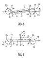
- Fig. 3 shows a drive device with a first drive axle 20 and a second drive axle 21. Between the first drive axle 20 and the second drive axle 21, a monomodal piezoelectric resonator 22 is arranged.
- the piezoelectric resonator 22 is rectangular and has at the top a first electrode 23 and on the back of a ground electrode, not shown.
- the first electrode 23 has a shape that enables the excitation of longitudinal vibrations.
- the piezoelectric resonator 22 is designed as a longitudinal oscillator.
- the piezoelectric resonator 22 has a first drive ram 25 on its end face 24a and a second drive ram 26 on the opposite end face 24b.
- the first drive ram 25 and the second drive ram 26 are fixed to the piezoelectric resonator 22 by means of an adhesive bond.
- the piezoelectric resonator 22 is excited by means of an electrical control unit, not shown, to longitudinal vibrations in the direction of the double arrow 27.
- the longitudinal axis of symmetry 28 of the piezoelectric resonator 22 is inclined at an angle ⁇ to the connecting line 29, which connects the centers 20 a and 21 a of the first drive axle 20 and the second drive axle 21.
- the piezoelectric resonator 22 with the first drive plunger 25 and the second drive plunger 26 is clamped by means of a biasing force F between the first drive axle 20 and the second drive axle 21.
- the first drive rod 25 and the second drive rod 26 exert microbumps in the direction of the double arrow 27 against the first drive axle 20 and the second drive axle 21, whereby both are rotated in the same direction of rotation 30.
- Fig. 4 shows a drive device with a first drive axle 31 and a second drive axle 32.
- the first axle 31 has a center 31a and the second axle 32 has a center 32a.
- a rectangular piezoelectric resonator 33 is arranged between the first drive axle 31 and the second drive axle 32.
- the piezoelectric resonator 33 has on the upper side a first electrode 35 and on the underside a ground electrode, not shown.
- the first electrode 35 has a shape that allows the excitation of bending vibrations.
- the piezoelectric resonator 33 to bending vibrations in the direction of Double Arrows 36 are stimulated.
- the piezoelectric resonator 33 has on its end face 33a a first drive tappet 37 and on its end face 33b a second drive tappet 38.
- the longitudinal axis of symmetry 39 of the piezoelectric resonator 33 is arranged offset parallel to the connecting line 40 between the center 31a of the first drive axle 31 and the center 32a of the second drive axle 32.
- the piezoelectric resonator 33 is clamped by means of a biasing force F in the direction of the arrow 43 against the first drive axle 31 and the second drive axle 32.
- Fig. 5 shows a drive device with a first drive axle 45, a second drive axle 46 and a third drive axle 47, which are arranged triangular. Between the first drive axle 45 and the third drive axle 47, a first piezoelectric resonator 48 and between the second drive axle 46 and the third drive axle 47, a second piezoelectric resonator 49 is arranged.
- the first piezoelectric resonator 48 and the second piezoelectric resonator 49 are referred to as bimodal pico-electric resonators corresponding to those in FIG Fig. 1 described embodiment executed.
- the first drive axle 45 is mounted in a first floating bearing 50, the second drive axle 46 in a second floating bearing 51 and the third drive axle 47 in a fixed bearing 52.
- the first floating camp 50 is movably mounted in a slot 53 and braced by means of a spring 54 in the direction of the first piezoelectric resonator 48.
- the slot 53 is located in a housing, not shown, of the drive device.
- the second floating bearing 51 is slidably mounted in a slot 55 and clamped by a spring 56 in the direction of the second piezoelectric resonator 49.
- the bearing 52 is fixedly secured to the housing, not shown.
- the first piezoelectric resonator 48 has a first drive rod 48 a, which bears against the first drive axle 45, and a second drive rod 48 b, which bears against the third drive axle 47.
- the second piezoelectric resonator 49 has a first drive rod 49 a, which abuts against the second drive axle 46, and a second drive rod 49 b, which bears against the third drive axle 47.
- the first drive shaft 45 is thus resiliently urged by the spring force of the spring 54 against the first piezoelectric element 48, whereby the first piezoelectric element 48 is resiliently clamped between the first drive axle 45 and the third drive axle 47.
- the second piezoelectric resonator 49 is resiliently clamped by means of the spring 56 between the second drive axle 46 and the third drive axle 47.
- the first piezoelectric resonator 48 and the second piezoelectric resonator 49 can be excited to elliptical vibrations by means of a control unit, not shown, whereby the drive tappets 48a, 48b, 49a and 49b a frictional force on the first drive axle 45, the second drive axle 46 and the third drive axle 47 exercise.
- the direction of rotation of the three drive shafts 45, 46 and 47 is the same and can by means of in the Fig. 5 not shown control unit, how to Fig. 1 described, be reversed.
- the rotational speed of the three drive shafts 45, 46 and 47 is substantially the same.
- the available torque of the third drive axle 47 is greater than the available torque of the first drive axle 45 and the second drive axle 46th
- Fig. 6 shows a drive device with a first drive axle 60, a second drive axle 61 and a third drive axle 62, which are arranged triangular.
- the first drive axle 60 is mounted in a floating bearing 63, the second drive axle 61 in a floating bearing 64 and the third drive axle 62 in a floating bearing 65.
- a first piezoelectric resonator 66 is arranged between the first drive axle 60 and the second drive axle 61.
- a second piezoelectric resonator 67 is arranged.
- a third piezoelectric resonator 68 is arranged.
- the first piezoelectric resonator 66, the second piezoelectric resonator 67, and the third piezoelectric resonator 68 are each referred to as bimodal piezoelectric resonators corresponding to those in FIG Fig. 1 described embodiment executed.
- the floating bearing 63 is biased by a spring 69 against a not-shown housing.
- the floating bearing 64 is biased by a spring 70 against the housing, not shown, and the floating bearing 65 is biased by a spring 71 against the housing, not shown.
- the first piezoelectric resonator 66 is resiliently clamped between the first drive axle 60 and the second drive axle 61
- the second piezoelectric resonator 67 is resiliently clamped between the first drive axle 60 and the third drive axle 62
- the third piezoelectric resonator 68 is resiliently interposed between the second Drive axle 61 and the third drive axle 62 clamped.
- the three piezoelectric resonators 66, 67 and 68 can by means of a control unit, not shown, as to Fig. 1 described to be excited to elliptical oscillations, whereby the first drive axle 60, the second drive axle 61 and the third drive axle 62 in the same Direction of rotation to be driven. A reversal of the direction of rotation is easy to realize by means of the electrical control. Due to the complete symmetrical arrangement of the drive device according to Fig. 6 Both the available torque and the speed of the three drive axles 60, 61 and 62 is the same.
- Fig. 7 shows a razor 72 with a first shaving head 73, a second shaving head 74 and a third shaving head 75.
- the first shaving head 73, the second shaving head 74 and the third shaving head 75 are by means of a driving device according to FIG Fig. 5 or a drive device according to Fig. 6 driven.
Landscapes
- Life Sciences & Earth Sciences (AREA)
- Forests & Forestry (AREA)
- Engineering & Computer Science (AREA)
- Mechanical Engineering (AREA)
- General Electrical Machinery Utilizing Piezoelectricity, Electrostriction Or Magnetostriction (AREA)
Claims (14)
- Dispositif d'entraînement avec un premier élément de rotation, un deuxième élément de rotation et un troisième élément de rotation, qui sont agencés en forme de triangle, dans lequel un premier élément d'entraînement piézoélectrique est agencé entre le premier élément de rotation et le deuxième élément de rotation et serré au moyen d'une force de précontrainte, lequel présente un résonateur piézoélectrique et au moins deux éléments de frottement se faisant face l'un l'autre et agencés au niveau du résonateur piézoélectrique, dans lequel respectivement un des éléments de frottement du premier élément d'entraînement appuie contre respectivement le premier ou le deuxième élément de rotation, et dans lequel des moyens électriques sont prévus pour activer une oscillation du résonateur piézoélectrique, caractérisé en ce qu'un deuxième élément d'entraînement piézoélectrique est agencé entre le premier élément de rotation et le troisième élément de rotation et serré au moyen d'une force de précontrainte, lequel présente un résonateur piézoélectrique et au moins deux éléments de frottement se faisant face l'un l'autre et agencés au niveau du résonateur piézoélectrique, dans lequel respectivement un des éléments de frottement du deuxième élément d'entraînement appuie contre respectivement le premier ou le troisième élément de rotation.
- Dispositif d'entraînement selon la revendication 1, caractérisé en ce qu'un troisième élément d'entraînement piézoélectrique est agencé entre le deuxième élément de rotation et le troisième élément de rotation et serré au moyen d'une force de précontrainte, lequel présente un résonateur piézoélectrique et au moins deux éléments de frottement se faisant face l'un l'autre et agencés au niveau du résonateur piézoélectrique, dans lequel respectivement un des éléments de frottement du troisième élément d'entraînement appuie contre respectivement le deuxième ou le troisième élément de rotation.
- Dispositif d'entraînement selon la revendication 1, caractérisé en ce que les résonateurs piézoélectriques sont réalisés sous forme de résonateurs monomode.
- Dispositif d'entraînement selon la revendication 1, caractérisé en ce que les résonateurs piézoélectriques sont réalisés sous forme de résonateurs bimode.
- Dispositif d'entraînement selon la revendication 4, caractérisé en ce que les éléments d'entraînement piézoélectriques présentent une plaque piézoélectrique essentiellement rectangulaire avec une première surface et une deuxième surface, en ce que la première surface présente au moins quatre électrodes et la deuxième surface présente au moins une électrode, en ce que respectivement une électrode est agencée dans chaque quadrant de la première surface et en ce que les éléments de frottement sont réalisés sous forme de poussoir d'entraînement en saillie par rapport à la plaque piézoélectrique.
- Dispositif d'entraînement selon la revendication 4, caractérisé en ce que la géométrie des résonateurs piézoélectriques est sélectionnée de telle sorte que les deux fréquences de résonance du résonateur piézoélectrique sont si proches les unes des autres que lors d'une excitation électrique l'une des fréquences de résonance excite l'autre fréquence de résonance.
- Dispositif d'entraînement selon la revendication 4, caractérisé en ce que la force de précontrainte, la géométrie des résonateurs piézoélectriques et les coefficients de frottement entre les éléments de frottement et les éléments de rotation sont dimensionnés de telle sorte que les éléments de frottement réalisent un mouvement essentiellement elliptique, l'axe de symétrie longitudinal de l'ellipse s'étendant de manière inclinée vers la ligne de jonction entre les deux éléments de rotation s'y rapportant.
- Dispositif d'entraînement selon la revendication 7, caractérisé en ce que la force de précontrainte, la géométrie des résonateurs piézoélectriques et les coefficients de frottement entre les éléments de frottement et les éléments de rotation sont dimensionnés de telle sorte que le sens de déplacement principal des éléments de frottement correspond essentiellement à l'angle de frottement entre les éléments de rotation et les éléments de frottement.
- Dispositif d'entraînement selon la revendication 1, caractérisé en ce que les matériaux des éléments de rotation et des éléments de frottement sont sélectionnés de telle sorte que l'angle de frottement se trouve dans une plage comprise entre 15° et 35°.
- Dispositif d'entraînement selon la revendication 1, caractérisé en ce que les éléments de frottement et/ou les surfaces des éléments de rotation sont en oxyde d'aluminium.
- Dispositif d'entraînement selon la revendication 1, caractérisé en ce qu'un des trois éléments de rotation est agencé dans un palier fixe et les deux autres éléments de rotation sont agencés respectivement dans un palier flottant, en ce que les deux éléments d'entraînement piézoélectriques sont agencés respectivement entre l'élément de rotation agencé dans le palier fixe et un des éléments de rotation agencés dans les paliers flottants et en ce que les paliers flottants sont précontraints contre l'élément d'entraînement piézoélectrique respectif au moyen d'une force de précontrainte.
- Dispositif d'entraînement selon la revendication 5, caractérisé en ce que le rapport longueur-largeur de la plaque piézoélectrique se trouve dans une plage comprise entre 1:3 et 1:4.
- Rasoir avec un dispositif d'entraînement selon la revendication 1.
- Appareil électroménager avec un dispositif d'entraînement selon la revendication 1.
Applications Claiming Priority (2)
| Application Number | Priority Date | Filing Date | Title |
|---|---|---|---|
| DE1997157139 DE19757139A1 (de) | 1997-12-20 | 1997-12-20 | Antriebsvorrichtung für wenigstens zwei Rotationselemente mit wenigstens einem piezoelektrischen Antriebselement |
| DE19757139 | 1997-12-20 |
Publications (3)
| Publication Number | Publication Date |
|---|---|
| EP0924778A2 EP0924778A2 (fr) | 1999-06-23 |
| EP0924778A3 EP0924778A3 (fr) | 2001-01-17 |
| EP0924778B1 true EP0924778B1 (fr) | 2008-11-26 |
Family
ID=7852920
Family Applications (1)
| Application Number | Title | Priority Date | Filing Date |
|---|---|---|---|
| EP19980204258 Expired - Lifetime EP0924778B1 (fr) | 1997-12-20 | 1998-12-15 | Dispositif de propulsion pour trois éléments de rotation avec au moins deux organes d'entraînement à type piézoélectrique |
Country Status (5)
| Country | Link |
|---|---|
| US (1) | US6121717A (fr) |
| EP (1) | EP0924778B1 (fr) |
| JP (1) | JP4201407B2 (fr) |
| CN (1) | CN1183610C (fr) |
| DE (2) | DE19757139A1 (fr) |
Cited By (1)
| Publication number | Priority date | Publication date | Assignee | Title |
|---|---|---|---|---|
| DE202014104464U1 (de) | 2014-09-19 | 2015-02-12 | Siglinde Lembens | Trockenrasierer mit neuartiger Schneidgeometrie |
Families Citing this family (27)
| Publication number | Priority date | Publication date | Assignee | Title |
|---|---|---|---|---|
| WO2000038309A1 (fr) * | 1998-12-21 | 2000-06-29 | Seiko Epson Corporation | Actionneur piezo-electrique, compteur de temps et dispositif portable |
| JP4328412B2 (ja) * | 1999-05-14 | 2009-09-09 | キヤノン株式会社 | 振動型アクチュエータおよび振動型駆動装置 |
| WO2000074153A1 (fr) * | 1999-05-31 | 2000-12-07 | Nanomotion Ltd. | Moteur piézoélectrique multicouche |
| US6242850B1 (en) * | 1999-07-28 | 2001-06-05 | Technology Commercialization Corp. | Piezoelectric motor and a disk drive using same |
| DE19942269A1 (de) * | 1999-09-04 | 2001-03-08 | Philips Corp Intellectual Pty | Piezoelektrische Antriebsvorrichtung |
| IL137206A0 (en) * | 1999-10-31 | 2001-07-24 | Nanomotion Ltd | Piezoelectric motors and motor driving configurations |
| DE10008937A1 (de) * | 2000-02-25 | 2001-08-30 | Philips Corp Intellectual Pty | Elektrischer Schaltkreis zur Ansteuerung von piezoelektrischen Antrieben |
| DE10010707C2 (de) * | 2000-03-04 | 2002-01-10 | Philips Corp Intellectual Pty | Piezoelektrischer Aktuator |
| ATE311034T1 (de) * | 2000-03-23 | 2005-12-15 | Elliptec Resonant Actuator Ag | Vibrationsantrieb und herstellungsverfahren sowie verwendung desselben |
| US6690101B2 (en) | 2000-03-23 | 2004-02-10 | Elliptec Resonant Actuator Ag | Vibratory motors and methods of making and using same |
| US6362557B1 (en) * | 2000-08-28 | 2002-03-26 | International Business Machines Corporation | Ultrasonic method and actuator for inducing motion of an object |
| US20050127789A1 (en) * | 2001-03-08 | 2005-06-16 | Magnussen Bjoern B. | Piezoelectric motors and methods for the production and operation thereof |
| US6388364B1 (en) * | 2001-03-15 | 2002-05-14 | Optovation (Canada) Corp. | Piezoelectric rotator |
| DE10113660A1 (de) * | 2001-03-21 | 2002-09-26 | Koninkl Philips Electronics Nv | Piezoelektrischer Antrieb |
| DE10146703A1 (de) | 2001-09-21 | 2003-04-10 | Elliptec Resonant Actuator Ag | Piezomotor mit Führung |
| ATE378724T1 (de) | 2002-02-06 | 2007-11-15 | Elliptec Resonant Actuator Ag | Steuerung eines piezoelektrischen motors |
| US7368853B2 (en) | 2002-04-22 | 2008-05-06 | Elliptec Resonant Actuator Aktiengesellschaft | Piezoelectric motors and methods for the production and operation thereof |
| CN1578934A (zh) * | 2002-08-30 | 2005-02-09 | 精工爱普生株式会社 | 模拟电子表 |
| JP2004260990A (ja) * | 2003-02-06 | 2004-09-16 | Seiko Epson Corp | 駆動装置および稼動装置 |
| US7242131B2 (en) * | 2004-05-12 | 2007-07-10 | Olympus Corporation | Ultrasonic motor |
| US7436101B1 (en) * | 2004-11-04 | 2008-10-14 | Elliptec Resonant Actuator Ag | Multistage piezoelectric drive |
| GB2420010A (en) * | 2004-11-05 | 2006-05-10 | Johnson Electric Sa | Piezoelectric motor with quadrant-type actuator |
| DE102008026429A1 (de) * | 2008-06-02 | 2009-12-10 | Physik Instrumente (Pi) Gmbh & Co. Kg | Ultraschallaktor |
| JP2012029478A (ja) * | 2010-07-23 | 2012-02-09 | Olympus Corp | 振動体及び超音波モータ |
| WO2014008394A1 (fr) * | 2012-07-03 | 2014-01-09 | Discovery Technology International, Inc. | Moteur linéaire piézoélectrique |
| DE102014225154B3 (de) * | 2014-12-08 | 2016-03-03 | Physik Instrumente (Pi) Gmbh & Co. Kg | Verfahren und Vorrichtung zur Ansteuerung eines piezoelektrischen Motors |
| CN108270369B (zh) * | 2018-02-28 | 2023-06-20 | 华侨大学 | 一种差动旋转压电步进电机及电激励方式 |
Citations (2)
| Publication number | Priority date | Publication date | Assignee | Title |
|---|---|---|---|---|
| DE2530045A1 (de) * | 1974-07-05 | 1976-02-05 | Ki Politekhn I Im 50 Letia Wel | Elektrischer motor |
| EP0712170A1 (fr) * | 1994-11-10 | 1996-05-15 | Nanomotion Ltd | Unité moteur piézoélectrique |
Family Cites Families (14)
| Publication number | Priority date | Publication date | Assignee | Title |
|---|---|---|---|---|
| SE436675B (sv) * | 1975-08-12 | 1985-01-14 | Ki Politekhnichsky I Im 50 Let | Elektrisk motor driven genom piezoelektriska krafter |
| SU765910A1 (ru) * | 1978-10-05 | 1980-09-23 | Каунасский Политехнический Институт Им. Антанаса Снечкуса | Вибродвигатель |
| SU817816A1 (ru) * | 1979-05-30 | 1981-03-30 | Каунасский Политехнический Институтим. Ahtahaca Снечкуса | Вибродвигатель |
| SU1128292A1 (ru) * | 1980-11-03 | 1984-12-07 | Киевский Ордена Ленина Политехнический Институт Им.50-Летия Великой Октябрьской Социалистической Революции | Пьезоэлектрический двигатель |
| AT384912B (de) * | 1982-04-16 | 1988-01-25 | Ki Polt I | Piezoelektrischer motor |
| JPS5989583A (ja) * | 1982-11-15 | 1984-05-23 | Aiwa Co Ltd | 圧電振動子を用いた駆動装置 |
| DE3433768A1 (de) * | 1983-09-16 | 1985-04-18 | Hitachi Maxell, Ltd., Ibaraki, Osaka | Piezo-elektrischer motor |
| US4663556A (en) * | 1984-01-11 | 1987-05-05 | Hitachi Maxell, Ltd. | Torsional mode ultrasonic vibrator |
| US4882500A (en) | 1986-06-04 | 1989-11-21 | Nippon Seimitsu Kogyo Kabushiki Kaisha | Method for converting standing wave vibrations into motion and standing wave motor therefor |
| JP2519936B2 (ja) | 1987-06-24 | 1996-07-31 | 京セラ株式会社 | 圧電アクチュエ−タ− |
| IL114656A0 (en) * | 1995-07-18 | 1995-11-27 | Nanomotion Ltd | Ceramic motor |
| FR2715780B1 (fr) * | 1994-02-01 | 1996-04-05 | Imra Europe Sa | Stator de moteur rotatif piézoélectrique et moteur rotatif piézoélectrique comportant un tel stator. |
| IL113291A0 (en) * | 1995-04-06 | 1995-07-31 | Nanomotion Ltd | A multi-axis rotation device |
| AU7075298A (en) * | 1997-12-15 | 1999-07-05 | Nanomotion Ltd. | Conveying means and method |
-
1997
- 1997-12-20 DE DE1997157139 patent/DE19757139A1/de not_active Withdrawn
-
1998
- 1998-11-30 US US09/201,045 patent/US6121717A/en not_active Expired - Fee Related
- 1998-12-15 DE DE59814321T patent/DE59814321D1/de not_active Expired - Fee Related
- 1998-12-15 EP EP19980204258 patent/EP0924778B1/fr not_active Expired - Lifetime
- 1998-12-15 JP JP35527198A patent/JP4201407B2/ja not_active Expired - Fee Related
- 1998-12-18 CN CNB981254357A patent/CN1183610C/zh not_active Expired - Fee Related
Patent Citations (2)
| Publication number | Priority date | Publication date | Assignee | Title |
|---|---|---|---|---|
| DE2530045A1 (de) * | 1974-07-05 | 1976-02-05 | Ki Politekhn I Im 50 Letia Wel | Elektrischer motor |
| EP0712170A1 (fr) * | 1994-11-10 | 1996-05-15 | Nanomotion Ltd | Unité moteur piézoélectrique |
Cited By (1)
| Publication number | Priority date | Publication date | Assignee | Title |
|---|---|---|---|---|
| DE202014104464U1 (de) | 2014-09-19 | 2015-02-12 | Siglinde Lembens | Trockenrasierer mit neuartiger Schneidgeometrie |
Also Published As
| Publication number | Publication date |
|---|---|
| DE59814321D1 (de) | 2009-01-08 |
| CN1183610C (zh) | 2005-01-05 |
| EP0924778A3 (fr) | 2001-01-17 |
| CN1225296A (zh) | 1999-08-11 |
| JPH11252950A (ja) | 1999-09-17 |
| US6121717A (en) | 2000-09-19 |
| EP0924778A2 (fr) | 1999-06-23 |
| JP4201407B2 (ja) | 2008-12-24 |
| DE19757139A1 (de) | 1999-06-24 |
Similar Documents
| Publication | Publication Date | Title |
|---|---|---|
| DE19757139A1 (de) | Antriebsvorrichtung für wenigstens zwei Rotationselemente mit wenigstens einem piezoelektrischen Antriebselement | |
| DE69032746T2 (de) | Vibrationsmotor | |
| DE69125666T2 (de) | Optischer Abtaster | |
| DE3415630C2 (fr) | ||
| DE69025984T2 (de) | Durch Vibration angetriebener Motor | |
| DE10154526B4 (de) | Piezoelektrisches Stellelement | |
| DE3500607C2 (de) | Torsionsschwingungs-Ultraschallvibrator sowie Torsionsschwingungs-Piezomotor | |
| EP1210759B1 (fr) | Commande piezo-electrique avec excitation produite par des ondes longitudinales et de flexion | |
| EP0313130A2 (fr) | Moteur électrique rotatif ou linéaire ayant son rotor commandé par des vibrations ultrasoniques | |
| DE3433768C2 (fr) | ||
| DE68917525T2 (de) | Antriebsanordnung vom Schwingungstyp. | |
| EP0306530A1 (fr) | Moteur piezoelectrique | |
| EP0436532A1 (fr) | Entrainement a oscillation de rotation | |
| EP1573282A1 (fr) | Dispositif pour determiner et/ou surveiller au moins une grandeur physique, comportant une commande piezoelectrique servant a l'excitation et a la detection d'oscillations | |
| EP1234346A1 (fr) | Entrainement piezo-electrique | |
| WO2010043517A2 (fr) | Dispositif de soudage, transducteur ultrasonore et procédé de soudage | |
| DE2936225A1 (de) | Piezoelektrischer resonator | |
| DE69607555T2 (de) | Vorrichtung für einen Ultraschallmotor | |
| EP1130756B1 (fr) | Actionneur piézoélectrique | |
| EP1581992A2 (fr) | Procede pour faire fonctionner un moteur piezo-electrique et moteur piezo-electrique comprenant un stator qui se presente sous la forme d'un oscillateur cylindrique creux | |
| EP1396012B2 (fr) | Entrainement piezoelectrique | |
| DE102007021338A1 (de) | Piezoelektrische Antriebsvorrichtung | |
| DE102011088304B4 (de) | Vorrichtung zur Bestimmung und/oder Überwachung mindestens einer Prozessgröße | |
| DE1488698A1 (de) | Elektrische Antriebsvorrichtung,insbesondere Antriebsvorrichtung fuer eine kleine mechanische Nutzlast | |
| DE3854692T2 (de) | Ultraschall-Antriebsvorrichtung. |
Legal Events
| Date | Code | Title | Description |
|---|---|---|---|
| PUAI | Public reference made under article 153(3) epc to a published international application that has entered the european phase |
Free format text: ORIGINAL CODE: 0009012 |
|
| AK | Designated contracting states |
Kind code of ref document: A2 Designated state(s): DE FR GB |
|
| AX | Request for extension of the european patent |
Free format text: AL;LT;LV;MK;RO;SI |
|
| RAP3 | Party data changed (applicant data changed or rights of an application transferred) |
Owner name: KONINKLIJKE PHILIPS ELECTRONICS N.V. Owner name: PHILIPS CORPORATE INTELLECTUAL PROPERTY GMBH |
|
| PUAL | Search report despatched |
Free format text: ORIGINAL CODE: 0009013 |
|
| AK | Designated contracting states |
Kind code of ref document: A3 Designated state(s): AT BE CH CY DE DK ES FI FR GB GR IE IT LI LU MC NL PT SE |
|
| AX | Request for extension of the european patent |
Free format text: AL;LT;LV;MK;RO;SI |
|
| 17P | Request for examination filed |
Effective date: 20010717 |
|
| AKX | Designation fees paid |
Free format text: DE FR GB |
|
| RAP1 | Party data changed (applicant data changed or rights of an application transferred) |
Owner name: KONINKLIJKE PHILIPS ELECTRONICS N.V. Owner name: PHILIPS CORPORATE INTELLECTUAL PROPERTY GMBH |
|
| RAP1 | Party data changed (applicant data changed or rights of an application transferred) |
Owner name: KONINKLIJKE PHILIPS ELECTRONICS N.V. Owner name: PHILIPS INTELLECTUAL PROPERTY & STANDARDS GMBH |
|
| 17Q | First examination report despatched |
Effective date: 20070813 |
|
| RTI1 | Title (correction) |
Free format text: DRIVING CIRCUIT FOR AT THREE ROTARY ELEMENTS WITH AT LEAST TWO PIEZOELECTRIC ACTUATORS |
|
| GRAP | Despatch of communication of intention to grant a patent |
Free format text: ORIGINAL CODE: EPIDOSNIGR1 |
|
| RIC1 | Information provided on ipc code assigned before grant |
Ipc: B26B 19/28 20060101ALI20080514BHEP Ipc: H01L 41/09 20060101AFI20080514BHEP |
|
| RTI1 | Title (correction) |
Free format text: DRIVING DEVICE FOR THREE ROTARY ELEMENTS WITH AT LEAST TWO PIEZOELECTRIC ACTUATORS |
|
| RIN1 | Information on inventor provided before grant (corrected) |
Inventor name: WENDT, MATTHIAS, DR. Inventor name: REICHINGER, CHRISTIAN, DR. Inventor name: DIEFENBACH, GERHARD |
|
| GRAS | Grant fee paid |
Free format text: ORIGINAL CODE: EPIDOSNIGR3 |
|
| GRAA | (expected) grant |
Free format text: ORIGINAL CODE: 0009210 |
|
| AK | Designated contracting states |
Kind code of ref document: B1 Designated state(s): DE FR GB |
|
| REG | Reference to a national code |
Ref country code: GB Ref legal event code: FG4D Free format text: NOT ENGLISH |
|
| REF | Corresponds to: |
Ref document number: 59814321 Country of ref document: DE Date of ref document: 20090108 Kind code of ref document: P |
|
| PGFP | Annual fee paid to national office [announced via postgrant information from national office to epo] |
Ref country code: GB Payment date: 20081231 Year of fee payment: 11 |
|
| PGFP | Annual fee paid to national office [announced via postgrant information from national office to epo] |
Ref country code: DE Payment date: 20090619 Year of fee payment: 11 |
|
| PLBE | No opposition filed within time limit |
Free format text: ORIGINAL CODE: 0009261 |
|
| STAA | Information on the status of an ep patent application or granted ep patent |
Free format text: STATUS: NO OPPOSITION FILED WITHIN TIME LIMIT |
|
| PGFP | Annual fee paid to national office [announced via postgrant information from national office to epo] |
Ref country code: FR Payment date: 20081219 Year of fee payment: 11 |
|
| 26N | No opposition filed |
Effective date: 20090827 |
|
| GBPC | Gb: european patent ceased through non-payment of renewal fee |
Effective date: 20091215 |
|
| REG | Reference to a national code |
Ref country code: FR Ref legal event code: ST Effective date: 20100831 |
|
| PG25 | Lapsed in a contracting state [announced via postgrant information from national office to epo] |
Ref country code: FR Free format text: LAPSE BECAUSE OF NON-PAYMENT OF DUE FEES Effective date: 20091231 |
|
| PG25 | Lapsed in a contracting state [announced via postgrant information from national office to epo] |
Ref country code: DE Free format text: LAPSE BECAUSE OF NON-PAYMENT OF DUE FEES Effective date: 20100701 |
|
| PG25 | Lapsed in a contracting state [announced via postgrant information from national office to epo] |
Ref country code: GB Free format text: LAPSE BECAUSE OF NON-PAYMENT OF DUE FEES Effective date: 20091215 |