EP0924793B1 - Dispositif d'antenne pour combiné radio-téléphone - Google Patents
Dispositif d'antenne pour combiné radio-téléphone Download PDFInfo
- Publication number
- EP0924793B1 EP0924793B1 EP98203306A EP98203306A EP0924793B1 EP 0924793 B1 EP0924793 B1 EP 0924793B1 EP 98203306 A EP98203306 A EP 98203306A EP 98203306 A EP98203306 A EP 98203306A EP 0924793 B1 EP0924793 B1 EP 0924793B1
- Authority
- EP
- European Patent Office
- Prior art keywords
- antenna
- radiating element
- radio communications
- ground plane
- communications handset
- Prior art date
- Legal status (The legal status is an assumption and is not a legal conclusion. Google has not performed a legal analysis and makes no representation as to the accuracy of the status listed.)
- Expired - Lifetime
Links
Images



Classifications
-
- H—ELECTRICITY
- H01—ELECTRIC ELEMENTS
- H01Q—ANTENNAS, i.e. RADIO AERIALS
- H01Q1/00—Details of, or arrangements associated with, antennas
- H01Q1/12—Supports; Mounting means
- H01Q1/22—Supports; Mounting means by structural association with other equipment or articles
- H01Q1/24—Supports; Mounting means by structural association with other equipment or articles with receiving set
- H01Q1/241—Supports; Mounting means by structural association with other equipment or articles with receiving set used in mobile communications, e.g. GSM
- H01Q1/242—Supports; Mounting means by structural association with other equipment or articles with receiving set used in mobile communications, e.g. GSM specially adapted for hand-held use
- H01Q1/243—Supports; Mounting means by structural association with other equipment or articles with receiving set used in mobile communications, e.g. GSM specially adapted for hand-held use with built-in antennas
-
- H—ELECTRICITY
- H04—ELECTRIC COMMUNICATION TECHNIQUE
- H04R—LOUDSPEAKERS, MICROPHONES, GRAMOPHONE PICK-UPS OR LIKE ACOUSTIC ELECTROMECHANICAL TRANSDUCERS; ELECTRIC HEARING AIDS; PUBLIC ADDRESS SYSTEMS
- H04R1/00—Details of transducers, loudspeakers or microphones
- H04R1/20—Arrangements for obtaining desired frequency or directional characteristics
- H04R1/22—Arrangements for obtaining desired frequency or directional characteristics for obtaining desired frequency characteristic only
- H04R1/225—Arrangements for obtaining desired frequency or directional characteristics for obtaining desired frequency characteristic only for telephonic receivers
Definitions
- the invention generally relates to radio communications handsets, and in particular to internal antenna arrangements.
- Half or quarter wavelength monopoles extend a significant length from the handset and have a number of disadvantages including the inconvenience of such a long protuberance which is easily broken and can be hazardous to users eyes for example.
- the inverted L antenna requires a significant physical length (quarter wavelength) for efficient operation, this is generally not possible within a handset so that a shortened L is generally inefficient.
- US4021810 discloses a 3D array of meander structure conductors above a ground plane which is complex to produce and is susceptible to the vagaries of manufacturing tolerances.
- WO96/38882 discloses a printed meandering monopole antenna extending from a mobile handset. While the meandering monopole is shorter than a standard monopole, it still represents an inconvenient protuberance outside the handset.
- WO93/12559 discloses a planar metallic sheet inverted F antenna having dependant elements angled with respect to the planar structure. As such it is delicate and complicated to manufacture.
- US-A-4 679 233 discloses a radio communications handset comprising a speaker having an adjacent volume of free space for acoustic enhancement and an antenna arrangement which incorporates said volume within the antenna arrangement, said antenna arrangement comprising a ground plane and a radiating element.
- the ground plane has a "u"-shaped form that encloses the free space volume.
- the radiating element is positioned above the ground plane remote from the free space volume location.
- a radio communications handset comprising:
- the radiating element is spaced a non-uniform distance over its length from said ground plane.
- the radiating element of the antenna arrangement comprises a meandering radiating element extending in a series of opposing bends from a radio-frequency feed point.
- the antenna arrangement further comprises a planar element connected to a free end of said radiating element and extending backwards of and substantially parallel with said radiating element
- said non-uniform spacing is such that the radiating element extends in an arc across the ground plane.
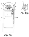
- a handset 1 comprising a speaker unit 10 and an adjacent volume of free space V extending behind the speaker unit (as shown in detail 1(b)) for acoustic enhancement; an antenna arrangement 2 comprising a ground plane 4 and a radiating element 3 extending from a radio frequency feed point 8 on the handsets printed circuit board (PCB) 11.
- PCB printed circuit board
- the radiating element 3 is curved with respect to the ground plane 4 and is arranged to fit around the peripheral edges of the acoustic enhancing volume of free space V, thereby incorporating the volume V within the antenna arrangement 2..
- the ground plane may be formed on the handset's PCB 11, or a metallic plane may be formed perpendicular to the PCB 11 for example by a shielding case.
- the radiating element 3 does not require tuning or matching stubs, nor grounding at any point along its length to achieve the desired resonant frequency from its compact dimensions.
- the radiating element is fed at one end while the other end is left free. This facilitates inclusion of handset elements such as speaker acoustic enhancing volumes between the radiating element 3 and the ground plane 4.
- the antenna arrangement 2 comprises a radiating element 3 and ground plane 4 connected to the handset's radio frequency transceiver circuitry 7 via a radio frequency feed point 8.
- the antenna 2 is shown in plan in figure 2a and in elevation in figure 2b.
- the radiating element 3 is a monopole structure which extends from the feed point 8 in a series of opposing bends which form a zigzag pattern of substantially parallel sections 6 separated by the bends 5.
- the radiating element 3 extends in a curve A with respect to the ground plane 4.
- the series of bends 5 and sections 6 which form the radiating element 3 need not form a regular pattern as is shown in the preferred embodiment.
- a further embodiment antenna 2 is shown in figures 4 (a) and (b) which comprises a dual band antenna 2 in which a plate or planar element 20 is connected to the free end of the radiating element 3 extending back from the connection and substantially parallel with the radiating element 3.
- the presence of the planar element 20 shifts the second harmonic of the fundamental resonant frequency of the antenna 2 along the frequency spectrum effectively introducing a further controllable frequency band.
- the planar element 20 shifts the second harmonic down the frequency spectrum depending on for example the planar elements length and distance from the radiating element 3.
- the dimensions of the planar element 20 and its physical relationship to the radiating element 3 are obtained experimentally for the desired frequency bands.
- Figure 4 shows the dual band antenna tuned to the 850 MHz and 1920 MHz frequency bands.
- the first preferred embodiment antenna arrangement has been shown to have an antenna efficiency of 75% at 850 MHz.
- the antenna efficiency at 850 MHz has been measured at 75%, and at the higher band of 1920 MHz an antenna efficiency of 91% has been achieved. This compares favourably with an antenna efficiency of 71% for a helix antenna at 920 MHz.
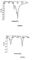
- Figure 5 shows the insertion loss of the single frequency antenna. It can be seen that adequate return loss (>10dB) is seen across the band, this can be improved by retuning. Placement of the intended speaker unit 10 inside the antenna 2 produced only a slight change in frequency which is readily retuned.
- Figures 6, 7 and 8 show respectively the insertion loss of the dual band antenna; the azimuth radiation pattern of the single band antenna; the azimuth radiation pattern of the dual band antenna at 850 MHz; and at 1920 MHz.
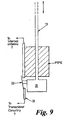
- FIG. 9 a further inventive aspect in which a switching arrangement is used to switch between the internal antenna 2 and an external antenna 13 such as a telescopically extendible monopole.
- an external antenna 13 such as a telescopically extendible monopole.
- the switching arrangement is shown in more detail in figure 9 and makes use of the manual engagement or disengagement of the external antenna 13.
- a metallic contact 31 attached at its base engages a flat spring contact 32 which disconnects the internal antenna 2 from the transceiver output 33, and simultaneously connects the external antenna 13 to the transceiver output 33.
- the reverse occurs when the external antenna 13 is manually pushed back into the handset.
- the switching arrangement could also be modified to operate using external antennas which are folded out or which are physically connected to the handset when required.
- Various alternative switching arrangements are conceivable by a person skilled in the art, including electronic switching, capacitive coupling, and other mechanical switching means.
Landscapes
- Engineering & Computer Science (AREA)
- Computer Networks & Wireless Communication (AREA)
- Support Of Aerials (AREA)
- Details Of Aerials (AREA)
Claims (8)
- Un combiné de radiocommunication (1) comprenant :un haut-parleur (10) ayant un volume d'espace libre V adjacent pour le renforcement acoustique;et une structure d'antenne (2) qui incorpore ledit volume à l'intérieur de la structure d'antenne, ladite structure d'antenne comprenant un plan de masse (4) et un élément rayonnant (3), caractérisé en ce que la structure est telle que le volume d'espace libre adjacent au haut-parleur soit placé entre le plan de masse et l'élément rayonnant.
- Un combiné de radiocommunication selon la revendication 1, caractérisé en ce que l'élément rayonnant (3) est de préférence espacé du plan de masse (4) d'une distance non uniforme sur sa longueur.
- Un combiné de radiocommunication selon la revendication 1 ou la revendication 2, caractérisé en ce que l'élément rayonnant de la structure d'antenne (1) comprend de préférence un élément rayonnant à méandres (3) s'étendant en une série de courbes opposées (5) à partir d'un point d'alimentation radiofréquence (8).
- Un combiné de radiocommunication selon la revendication 3, caractérisé en ce que les courbes opposées (5) dans l'élément rayonnant (3) sont établies dans plus d'un plan.
- Un combiné de radiocommunication selon l'une quelconque des revendications précédentes, caractérisé en ce que la structure d'antenne (2) comprend en outre un élément plan (20) connecté à l'extrémité libre de l'élément rayonnant (3) et s'étendant vers l'arrière de l'élément rayonnant et de façon sensiblement parallèle à celui-ci.
- Un combiné de radiocommunication selon l'une quelconque des revendications 3 à 5, caractérisé en ce que l'élément rayonnant (3) est un élément rayonnant d'antenne monopôle.
- Un combiné de radiocommunication selon l'une quelconque des revendications précédentes, caractérisé en ce que le combiné comprend en outre :une antenne externe extensible (13);un moyen émetteur-récepteur radiofréquence (7); etun moyen de commutation d'antenne (31, 32) qui est agencé pour commuter entre le moyen émetteur-récepteur (7) et l'antenne externe (13) ou la structure d'antenne (2), sous l'effet de l'extension ou de la rétraction manuelle de l'antenne externe.
- Un combiné de radiocommunication selon l'une quelconque des revendications 2 à 7, caractérisé en ce que l'écartement non uniforme est tel que l'élément rayonnant s'étende en un arc sur l'étendue du plan de masse.
Applications Claiming Priority (2)
| Application Number | Priority Date | Filing Date | Title |
|---|---|---|---|
| US995602 | 1997-12-22 | ||
| US08/995,602 US6304222B1 (en) | 1997-12-22 | 1997-12-22 | Radio communications handset antenna arrangements |
Publications (3)
| Publication Number | Publication Date |
|---|---|
| EP0924793A2 EP0924793A2 (fr) | 1999-06-23 |
| EP0924793A3 EP0924793A3 (fr) | 2000-03-29 |
| EP0924793B1 true EP0924793B1 (fr) | 2003-03-26 |
Family
ID=25541993
Family Applications (1)
| Application Number | Title | Priority Date | Filing Date |
|---|---|---|---|
| EP98203306A Expired - Lifetime EP0924793B1 (fr) | 1997-12-22 | 1998-09-30 | Dispositif d'antenne pour combiné radio-téléphone |
Country Status (5)
| Country | Link |
|---|---|
| US (1) | US6304222B1 (fr) |
| EP (1) | EP0924793B1 (fr) |
| CA (1) | CA2251314C (fr) |
| DE (1) | DE69812565T2 (fr) |
| GB (2) | GB9804103D0 (fr) |
Cited By (2)
| Publication number | Priority date | Publication date | Assignee | Title |
|---|---|---|---|---|
| US7554490B2 (en) | 2000-01-19 | 2009-06-30 | Fractus, S.A. | Space-filling miniature antennas |
| US8738103B2 (en) | 2006-07-18 | 2014-05-27 | Fractus, S.A. | Multiple-body-configuration multimedia and smartphone multifunction wireless devices |
Families Citing this family (28)
| Publication number | Priority date | Publication date | Assignee | Title |
|---|---|---|---|---|
| DK174546B1 (da) * | 1998-12-21 | 2003-05-19 | Sony Ericsson Mobile Comm Ab | Et kommunikationsapparat |
| WO2001009976A1 (fr) * | 1999-07-29 | 2001-02-08 | Siemens Aktiengesellschaft | Appareil radio avec boitier comportant un corps creux destine a accueillir un element d'antenne |
| EP1223637B1 (fr) | 1999-09-20 | 2005-03-30 | Fractus, S.A. | Antennes multiniveau |
| FR2802045B1 (fr) * | 1999-12-07 | 2002-02-15 | Sagem | Poste telephonique compact de reseau cellulaire |
| FR2802709B1 (fr) * | 1999-12-15 | 2005-08-05 | Canon Europa Nv | Dispositif d'agencement d'une antenne filaire dans un appareil de communication |
| FI114592B (fi) * | 2000-06-30 | 2004-11-15 | Nokia Corp | Kytkin- ja liitinjärjestely ulkoisten ja sisäisten antennien kytkemiseksi esimerkiksi laajennuskorttiin |
| FI115341B (fi) * | 2000-08-29 | 2005-04-15 | Nokia Corp | Matkaviestin ja matkaviestimen antennisovitelma |
| DE10052909A1 (de) * | 2000-10-25 | 2002-05-08 | Siemens Ag | Kommunikationsendgerät |
| DE10063242C2 (de) | 2000-12-19 | 2003-02-20 | Siemens Ag | Kommunikationsendgerät mit Antenne |
| FR2824216B1 (fr) * | 2001-04-30 | 2003-08-08 | Sagem | Terminal de radiotelephonie cellulaire a antenne bi-bande integree et l'antenne correspondante |
| FI117233B (fi) * | 2001-06-06 | 2006-07-31 | Flextronics Odm Luxembourg Sa | Menetelmä päätelaitteen akustisten ominaisuuksien parantamiseksi ja päätelaite |
| US6906667B1 (en) * | 2002-02-14 | 2005-06-14 | Ethertronics, Inc. | Multi frequency magnetic dipole antenna structures for very low-profile antenna applications |
| US20030003970A1 (en) * | 2001-06-28 | 2003-01-02 | Alan Johnson | Portable communications device |
| FR2829651B1 (fr) | 2001-09-13 | 2005-06-24 | Cit Alcatel | Composant pour terminal de radiocommunication constituant antenne, haut-parleur et sonnerie |
| ES2239700T3 (es) * | 2001-11-30 | 2005-10-01 | Sagem Sa | Telefono movil con un elemento integrado en el espacio entre la antena y la placa base. |
| US6717551B1 (en) | 2002-11-12 | 2004-04-06 | Ethertronics, Inc. | Low-profile, multi-frequency, multi-band, magnetic dipole antenna |
| US6744410B2 (en) * | 2002-05-31 | 2004-06-01 | Ethertronics, Inc. | Multi-band, low-profile, capacitively loaded antennas with integrated filters |
| US6943730B2 (en) | 2002-04-25 | 2005-09-13 | Ethertronics Inc. | Low-profile, multi-frequency, multi-band, capacitively loaded magnetic dipole antenna |
| US7084813B2 (en) * | 2002-12-17 | 2006-08-01 | Ethertronics, Inc. | Antennas with reduced space and improved performance |
| US6919857B2 (en) * | 2003-01-27 | 2005-07-19 | Ethertronics, Inc. | Differential mode capacitively loaded magnetic dipole antenna |
| US7123209B1 (en) * | 2003-02-26 | 2006-10-17 | Ethertronics, Inc. | Low-profile, multi-frequency, differential antenna structures |
| DE10357176A1 (de) * | 2003-12-06 | 2005-06-30 | Modine Manufacturing Co., Racine | Kondensator |
| US7193565B2 (en) * | 2004-06-05 | 2007-03-20 | Skycross, Inc. | Meanderline coupled quadband antenna for wireless handsets |
| US7113135B2 (en) * | 2004-06-08 | 2006-09-26 | Skycross, Inc. | Tri-band antenna for digital multimedia broadcast (DMB) applications |
| US7428431B2 (en) * | 2005-07-06 | 2008-09-23 | Kyocera Wireless Corp. | Extendable antenna and speaker box |
| WO2008119699A1 (fr) | 2007-03-30 | 2008-10-09 | Fractus, S.A. | Dispositif sans fil comprenant un système d'antenne multibande |
| US11862838B2 (en) | 2020-04-17 | 2024-01-02 | Apple Inc. | Electronic devices having wideband antennas |
| US11417951B2 (en) | 2020-09-01 | 2022-08-16 | Apple Inc. | Electronic devices having antennas that radiate through three-dimensionally curved cover layers |
Family Cites Families (18)
| Publication number | Priority date | Publication date | Assignee | Title |
|---|---|---|---|---|
| FI379774A7 (fr) | 1974-12-31 | 1976-07-01 | Martti Eelis Tiuri | |
| US4679233A (en) * | 1985-08-30 | 1987-07-07 | Motorola, Inc. | Microphone |
| US4860020A (en) | 1987-04-30 | 1989-08-22 | The Aerospace Corporation | Compact, wideband antenna system |
| JPH01317001A (ja) * | 1988-06-17 | 1989-12-21 | Mitsubishi Electric Corp | アンテナ切替装置 |
| US4876709A (en) * | 1988-09-08 | 1989-10-24 | Dynascan Corporation | Antenna for cordless telephone system |
| AT396532B (de) | 1991-12-11 | 1993-10-25 | Siemens Ag Oesterreich | Antennenanordnung, insbesondere für kommunikationsendgeräte |
| KR0150247B1 (ko) * | 1993-02-25 | 1998-11-02 | 안쏘니 제이. 살리, 주니어 | 외부 안테니가 은폐된 수신기 |
| FR2703550B1 (fr) * | 1993-03-30 | 1995-05-24 | Sagem | Radiotéléphone portatif à écoute amplifiée. |
| CN1094663C (zh) * | 1994-03-08 | 2002-11-20 | 泰利泰尔有限责任公司 | 手持式发送和/或接收装置 |
| WO1996027219A1 (fr) | 1995-02-27 | 1996-09-06 | The Chinese University Of Hong Kong | Antenne en f-inverse a serpentement |
| WO1996038882A1 (fr) | 1995-06-02 | 1996-12-05 | Ericsson Inc. | Antenne unipolaire imprimee multibande |
| GB2303968B (en) * | 1995-08-03 | 1999-11-10 | Nokia Mobile Phones Ltd | Antenna |
| US5696517A (en) * | 1995-09-28 | 1997-12-09 | Murata Manufacturing Co., Ltd. | Surface mounting antenna and communication apparatus using the same |
| JP3166589B2 (ja) | 1995-12-06 | 2001-05-14 | 株式会社村田製作所 | チップアンテナ |
| TW356610B (en) * | 1996-02-19 | 1999-04-21 | Murata Mfg Corp | Antenna apparatus and communication apparatus using the same |
| EP0806810A3 (fr) * | 1996-05-07 | 1998-04-08 | Ascom Tech Ag | Antenne formée par un élément résonnant en forme de bande sur un plan de masse |
| GB9627091D0 (en) * | 1996-12-31 | 1997-02-19 | Northern Telecom Ltd | An inverted E antenna |
| FI112723B (fi) * | 1997-03-27 | 2003-12-31 | Nokia Corp | Langattomien viestimien antenni |
-
1997
- 1997-12-22 US US08/995,602 patent/US6304222B1/en not_active Expired - Lifetime
-
1998
- 1998-02-27 GB GBGB9804103.1A patent/GB9804103D0/en not_active Ceased
- 1998-02-27 GB GBGB9804104.9A patent/GB9804104D0/en not_active Ceased
- 1998-09-30 EP EP98203306A patent/EP0924793B1/fr not_active Expired - Lifetime
- 1998-09-30 DE DE69812565T patent/DE69812565T2/de not_active Expired - Lifetime
- 1998-10-23 CA CA002251314A patent/CA2251314C/fr not_active Expired - Lifetime
Cited By (9)
| Publication number | Priority date | Publication date | Assignee | Title |
|---|---|---|---|---|
| US7554490B2 (en) | 2000-01-19 | 2009-06-30 | Fractus, S.A. | Space-filling miniature antennas |
| US8207893B2 (en) | 2000-01-19 | 2012-06-26 | Fractus, S.A. | Space-filling miniature antennas |
| US8212726B2 (en) | 2000-01-19 | 2012-07-03 | Fractus, Sa | Space-filling miniature antennas |
| US8471772B2 (en) | 2000-01-19 | 2013-06-25 | Fractus, S.A. | Space-filling miniature antennas |
| US8558741B2 (en) | 2000-01-19 | 2013-10-15 | Fractus, S.A. | Space-filling miniature antennas |
| US8610627B2 (en) | 2000-01-19 | 2013-12-17 | Fractus, S.A. | Space-filling miniature antennas |
| US9331382B2 (en) | 2000-01-19 | 2016-05-03 | Fractus, S.A. | Space-filling miniature antennas |
| US8738103B2 (en) | 2006-07-18 | 2014-05-27 | Fractus, S.A. | Multiple-body-configuration multimedia and smartphone multifunction wireless devices |
| US9099773B2 (en) | 2006-07-18 | 2015-08-04 | Fractus, S.A. | Multiple-body-configuration multimedia and smartphone multifunction wireless devices |
Also Published As
| Publication number | Publication date |
|---|---|
| GB9804103D0 (en) | 1998-04-22 |
| DE69812565D1 (de) | 2003-04-30 |
| CA2251314C (fr) | 2007-03-13 |
| EP0924793A3 (fr) | 2000-03-29 |
| GB9804104D0 (en) | 1998-04-22 |
| DE69812565T2 (de) | 2003-09-25 |
| EP0924793A2 (fr) | 1999-06-23 |
| CA2251314A1 (fr) | 1999-06-22 |
| US6304222B1 (en) | 2001-10-16 |
Similar Documents
| Publication | Publication Date | Title |
|---|---|---|
| EP0924793B1 (fr) | Dispositif d'antenne pour combiné radio-téléphone | |
| KR100723086B1 (ko) | 비대칭 다이폴 안테나 어셈블리 | |
| US7148847B2 (en) | Small-size, low-height antenna device capable of easily ensuring predetermined bandwidth | |
| US4571595A (en) | Dual band transceiver antenna | |
| EP1210745B1 (fr) | Petite antenne multibande | |
| US7755545B2 (en) | Antenna and method of manufacturing the same, and portable wireless terminal using the same | |
| EP0655797B1 (fr) | Antenne microbande accordable avec un accouplement à fente quart d'onde | |
| US6218992B1 (en) | Compact, broadband inverted-F antennas with conductive elements and wireless communicators incorporating same | |
| US6204826B1 (en) | Flat dual frequency band antennas for wireless communicators | |
| US6100848A (en) | Multiple band printed monopole antenna | |
| EP1204159A2 (fr) | Dispositif d'antenne | |
| US6229487B1 (en) | Inverted-F antennas having non-linear conductive elements and wireless communicators incorporating the same | |
| EP1057223A1 (fr) | Antenne double bande pour equipement radioelectrique terminal | |
| JPH10209738A (ja) | 逆e型アンテナ | |
| WO1996038882A9 (fr) | Antenne unipolaire imprimee multibande | |
| JP2002009539A (ja) | 移動電話のための統合アンテナ | |
| US6567047B2 (en) | Multi-band in-series antenna assembly | |
| EP2242143A1 (fr) | Antenne ayant longueur électrique accrue et dispositif de communication sans fil comprenant celle-ci | |
| KR20020015694A (ko) | 평판식 모노폴 안테나 | |
| EP0470797A2 (fr) | Arrangement d'antenne | |
| EP2047561A2 (fr) | Système d'antenne | |
| KR200284259Y1 (ko) | 지그재그형 선로를 갖는 무선 단말기용 안테나 | |
| JPH09232854A (ja) | 移動無線機用小型平面アンテナ装置 | |
| KR100896441B1 (ko) | 광대역 안테나 | |
| KR100861865B1 (ko) | 무선 단말기 |
Legal Events
| Date | Code | Title | Description |
|---|---|---|---|
| PUAI | Public reference made under article 153(3) epc to a published international application that has entered the european phase |
Free format text: ORIGINAL CODE: 0009012 |
|
| AK | Designated contracting states |
Kind code of ref document: A2 Designated state(s): DE FI FR GB IT SE |
|
| AX | Request for extension of the european patent |
Free format text: AL;LT;LV;MK;RO;SI |
|
| RAP3 | Party data changed (applicant data changed or rights of an application transferred) |
Owner name: NORTEL NETWORKS CORPORATION |
|
| PUAL | Search report despatched |
Free format text: ORIGINAL CODE: 0009013 |
|
| AK | Designated contracting states |
Kind code of ref document: A3 Designated state(s): AT BE CH CY DE DK ES FI FR GB GR IE IT LI LU MC NL PT SE |
|
| AX | Request for extension of the european patent |
Free format text: AL;LT;LV;MK;RO;SI |
|
| RAP1 | Party data changed (applicant data changed or rights of an application transferred) |
Owner name: NORTEL NETWORKS LIMITED |
|
| 17P | Request for examination filed |
Effective date: 20000929 |
|
| AKX | Designation fees paid |
Free format text: DE FI FR GB IT SE |
|
| 17Q | First examination report despatched |
Effective date: 20020423 |
|
| GRAH | Despatch of communication of intention to grant a patent |
Free format text: ORIGINAL CODE: EPIDOS IGRA |
|
| GRAH | Despatch of communication of intention to grant a patent |
Free format text: ORIGINAL CODE: EPIDOS IGRA |
|
| GRAA | (expected) grant |
Free format text: ORIGINAL CODE: 0009210 |
|
| AK | Designated contracting states |
Designated state(s): DE FI FR GB IT SE |
|
| PG25 | Lapsed in a contracting state [announced via postgrant information from national office to epo] |
Ref country code: IT Free format text: LAPSE BECAUSE OF FAILURE TO SUBMIT A TRANSLATION OF THE DESCRIPTION OR TO PAY THE FEE WITHIN THE PRESCRIBED TIME-LIMIT;WARNING: LAPSES OF ITALIAN PATENTS WITH EFFECTIVE DATE BEFORE 2007 MAY HAVE OCCURRED AT ANY TIME BEFORE 2007. THE CORRECT EFFECTIVE DATE MAY BE DIFFERENT FROM THE ONE RECORDED. Effective date: 20030326 Ref country code: FI Free format text: LAPSE BECAUSE OF FAILURE TO SUBMIT A TRANSLATION OF THE DESCRIPTION OR TO PAY THE FEE WITHIN THE PRESCRIBED TIME-LIMIT Effective date: 20030326 |
|
| REG | Reference to a national code |
Ref country code: GB Ref legal event code: FG4D |
|
| REF | Corresponds to: |
Ref document number: 69812565 Country of ref document: DE Date of ref document: 20030430 Kind code of ref document: P |
|
| PG25 | Lapsed in a contracting state [announced via postgrant information from national office to epo] |
Ref country code: SE Free format text: LAPSE BECAUSE OF FAILURE TO SUBMIT A TRANSLATION OF THE DESCRIPTION OR TO PAY THE FEE WITHIN THE PRESCRIBED TIME-LIMIT Effective date: 20030626 |
|
| RAP2 | Party data changed (patent owner data changed or rights of a patent transferred) |
Owner name: NORTEL NETWORKS LIMITED |
|
| ET | Fr: translation filed | ||
| PLBE | No opposition filed within time limit |
Free format text: ORIGINAL CODE: 0009261 |
|
| STAA | Information on the status of an ep patent application or granted ep patent |
Free format text: STATUS: NO OPPOSITION FILED WITHIN TIME LIMIT |
|
| 26N | No opposition filed |
Effective date: 20031230 |
|
| REG | Reference to a national code |
Ref country code: GB Ref legal event code: 732E Free format text: REGISTERED BETWEEN 20130502 AND 20130508 |
|
| REG | Reference to a national code |
Ref country code: GB Ref legal event code: 732E Free format text: REGISTERED BETWEEN 20130509 AND 20130515 |
|
| REG | Reference to a national code |
Ref country code: FR Ref legal event code: TP Owner name: APPLE INC., US Effective date: 20130515 |
|
| REG | Reference to a national code |
Ref country code: DE Ref legal event code: R082 Ref document number: 69812565 Country of ref document: DE Representative=s name: BARDEHLE PAGENBERG PARTNERSCHAFT MBB PATENTANW, DE Effective date: 20130801 Ref country code: DE Ref legal event code: R082 Ref document number: 69812565 Country of ref document: DE Representative=s name: BARDEHLE PAGENBERG PARTNERSCHAFT MBB PATENTANW, DE Effective date: 20140313 Ref country code: DE Ref legal event code: R081 Ref document number: 69812565 Country of ref document: DE Owner name: APPLE INC., CUPERTINO, US Free format text: FORMER OWNER: NORTEL NETWORKS LTD., ST. LAURENT, QUEBEC, CA Effective date: 20140313 Ref country code: DE Ref legal event code: R081 Ref document number: 69812565 Country of ref document: DE Owner name: APPLE INC., US Free format text: FORMER OWNER: NORTEL NETWORKS LTD., ST. LAURENT, CA Effective date: 20140313 |
|
| REG | Reference to a national code |
Ref country code: FR Ref legal event code: PLFP Year of fee payment: 19 |
|
| REG | Reference to a national code |
Ref country code: FR Ref legal event code: PLFP Year of fee payment: 20 |
|
| PGFP | Annual fee paid to national office [announced via postgrant information from national office to epo] |
Ref country code: GB Payment date: 20170927 Year of fee payment: 20 Ref country code: FR Payment date: 20170810 Year of fee payment: 20 |
|
| PGFP | Annual fee paid to national office [announced via postgrant information from national office to epo] |
Ref country code: DE Payment date: 20170927 Year of fee payment: 20 |
|
| REG | Reference to a national code |
Ref country code: DE Ref legal event code: R071 Ref document number: 69812565 Country of ref document: DE |
|
| REG | Reference to a national code |
Ref country code: GB Ref legal event code: PE20 Expiry date: 20180929 |
|
| PG25 | Lapsed in a contracting state [announced via postgrant information from national office to epo] |
Ref country code: GB Free format text: LAPSE BECAUSE OF EXPIRATION OF PROTECTION Effective date: 20180929 |