EP0924937A2 - Projecteur numérique avec système optique pour compenser la différence de longueur d'un chemin optique - Google Patents
Projecteur numérique avec système optique pour compenser la différence de longueur d'un chemin optique Download PDFInfo
- Publication number
- EP0924937A2 EP0924937A2 EP98123857A EP98123857A EP0924937A2 EP 0924937 A2 EP0924937 A2 EP 0924937A2 EP 98123857 A EP98123857 A EP 98123857A EP 98123857 A EP98123857 A EP 98123857A EP 0924937 A2 EP0924937 A2 EP 0924937A2
- Authority
- EP
- European Patent Office
- Prior art keywords
- light
- mirror
- light modulators
- modulators
- digital projector
- Prior art date
- Legal status (The legal status is an assumption and is not a legal conclusion. Google has not performed a legal analysis and makes no representation as to the accuracy of the status listed.)
- Withdrawn
Links
Images


Classifications
-
- H—ELECTRICITY
- H04—ELECTRIC COMMUNICATION TECHNIQUE
- H04N—PICTORIAL COMMUNICATION, e.g. TELEVISION
- H04N9/00—Details of colour television systems
- H04N9/12—Picture reproducers
- H04N9/31—Projection devices for colour picture display, e.g. using electronic spatial light modulators [ESLM]
- H04N9/3102—Projection devices for colour picture display, e.g. using electronic spatial light modulators [ESLM] using two-dimensional electronic spatial light modulators
- H04N9/3105—Projection devices for colour picture display, e.g. using electronic spatial light modulators [ESLM] using two-dimensional electronic spatial light modulators for displaying all colours simultaneously, e.g. by using two or more electronic spatial light modulators
-
- H—ELECTRICITY
- H04—ELECTRIC COMMUNICATION TECHNIQUE
- H04N—PICTORIAL COMMUNICATION, e.g. TELEVISION
- H04N5/00—Details of television systems
- H04N5/74—Projection arrangements for image reproduction, e.g. using eidophor
- H04N5/7416—Projection arrangements for image reproduction, e.g. using eidophor involving the use of a spatial light modulator, e.g. a light valve, controlled by a video signal
- H04N5/7441—Projection arrangements for image reproduction, e.g. using eidophor involving the use of a spatial light modulator, e.g. a light valve, controlled by a video signal the modulator being an array of liquid crystal cells
Definitions
- the invention relates to a digital projector having an array of light modulators displaying image information, an optical system arranged downstream of the light modulators and a projection lens following the optical system, the optical system being made up of mirrors and prisms, with the mirrors and prisms being arranged such that the light beams coming from the individual light modulators are combined prior to entering the projection lens.
- WO 95/33343 discloses a projection system for high-definition images.
- a stack of three transparent LCD displays is illuminated by one light source.
- the light exiting from the LCD display is concentrated by means of an optical array and projected as a real image onto a screen. Since the images have an optical path length difference when split up between blue, red and green, the difference is compensated before the projection.
- dichroitic mirrors are provided that are arranged depending on the structure of the LCD display.
- a further display for color images is disclosed in EP-0 458 270 A2.
- Three light modulators red, green and blue
- the optical system comprises several conventional prisms and a dichroitic mirror.
- EP-0 431 716 A2 discloses a device permitting a parallax-free projection onto a CRT.
- the LCD's are arranged in a row. To avoid projection errors in the projection plane, a geometrical correction of the beams is performed.
- Each LCD is assigned a projection lens that displays on the projection screen the light that passes through the red, green or blue filters and that has been corrected by aligning lenses.
- the object underlying the present invention is therefore to provide a digital projector in which the individual light modulators and the optical system necessary for projection are arranged and structured such that differences in the optical path length are compensated.
- the optical system is to be of simple design, inexpensive and easy to service.
- the advantage of the digital projector is that a simple structure of the optical system is made possible by the checkerboard formation of the light modulators and can be used for compensation of the optical path length difference of the individual active light modulators.
- the specific arrangement of the light modulators means that the optical system manages with a minimum of optical components.
- the components of the optical system exclusively comprise mirrors or prisms and a color-combining prism. This permits a particularly inexpensive arrangement, as no complicated correction of projection errors etc. is necessary, unlike with lenses.
- a digital projector (not shown) comprises several light modulators arranged in a plane 7 and in a row.
- three light modulators are arranged in a row 2.
- the row arrangement of the light modulators comprises a red, a blue and a green light modulator 4, 6 and 8, the sequence of which can be selected as required in the row 2.
- the length of the diagonal of a light modulator is 63.5 mm (2.5 inches) and the ratio of length to width is 4 to 3.
- Each of the light modulators is made up of a large number of pixel elements (not shown) and produced on a chip in accordance with known lithographic processes. The light coming from the pixel elements of the light modulators is emitted at a spatial angle of ⁇ 15°.
- the light beams coming from the individual light modulators 4, 6 and 8 must be combined before projection without an optical path length difference. It is assumed in the following description that the row 2 of light modulators 4, 6 and 8 is laid out in a sequence of, from left to right, a red light modulator 4, a blue light modulator 6 and a green light modulator 8. It is clear for a person skilled in the art that any required sequence can be selected here and that the above embodiment can in no way be deemed as a restriction.
- Figs. 2 and 3 show two different embodiments of optical systems 20 and 30 used for combination of light beams coming from the light modulators and compensating the optical path difference.
- the optical system 20 shown in Fig. 2 comprises a large number of eleven mirrors and one projection lens 21.
- the light modulators 4, 6 and 8 have between their centers a distance b, shown in Figs. 2 and 3 as a double-headed arrow.
- the row 2 of light modulators has a distance a from the projection lens 21, likewise shown as a double-headed arrow in Figs. 2 and 3.
- the mirrors are arranged such that each light beam emitted by the light modulators 4, 6 and 8 covers an optical path of a + 2b.
- a first mirror 22 R1 is arranged at an angle of 45° in order to deflect the light coming from the red light modulator 4 parallel to row 2 of the light modulators.
- a third mirror 22 R3 is provided at an angle of -45° and deflects the light to a fourth mirror 22 R4 that is arranged at a distance of 0.5b and at an angle of -45° in front of the projection lens 21 with respect to the beam path.
- a first mirror 23 B1 is arranged at an angle of 45° in order to deflect the light coming from the blue light modulator 6 parallel to row 2 of the light modulators.
- a further mirror 23 B2 arranged at an angle of 45° and at a distance b from the first mirror 23 B1 deflects the light back into the propagation direction of the light beams coming from the light modulators.
- a third mirror 23 B3 is provided at an angle of -45° and deflects the light to a fourth mirror 23 B4 that is identical to the fourth mirror 22 R4 for reflection of the red light, and hence arranged at a distance of 1b and at an angle of -45° in front of the projection lens 21 with respect to the beam path.
- a first mirror 24 G1 is arranged at an angle of - 45° in order to deflect the light coming from the green light modulator 8 parallel to row 2 of the light modulators.
- a further mirror 24 G2 arranged at an angle of -45° and at a distance of 1.5b from the first mirror 24 G1 deflects the light back into the propagation direction of the light beams coming from the light modulators.
- a third mirror 23 B3 is provided at an angle of 45° and deflects the light to a fourth mirror 24 G4 that is arranged at a distance of 0.5b and at an angle of 45° in front of the projection lens 21 with respect to the beam path.
- Fig. 3 shows an optical system 30 that uses lenses and mirrors for compensation of the optical path length difference.
- a lens 31 R is provided and in front of the green light modulator 8 a lens 33 G , both lenses 31 R and 33 G having an appropriate focal length and allowing a projection 34 and 38 of the appropriate light modulators 4 and 8 which is a one-to-one projection of the respective light modulators 4 and 8.
- the correction of the optical path length difference is achieved by a further lens 32 B arranged in front of the blue light modulator 6.
- the focal length of this lens 32 B is selected such that the optical path length differences between the red and the blue light modulators 4 and 6 and between the green and the blue light modulators 8 and 6 are compensated by the resultant projection 36.
- a first mirror 35 R1 inclined at 45° is provided and deflects the light beams onto a second mirror 35 R2 at an angle of 45° and arranged in front of the projection lens 21 with respect to the beam path.
- a first mirror 37 G1 inclined at an angle of -45° is provided and deflects the light beams onto a second mirror 37 G2 at an angle of -45° and arranged in front of the projection lens 21 with respect to the beam path.
- the three projections 34, 36 and 38 are combined at the point at which the second mirrors 35 R2 and 37 G2 are located, and displayed without optical path length difference.
- the lenses 31 R , 32 B and 33 G for generating the projections 34, 36 and 38 are projection lenses.
- the lenses in front of the red and green light modulators 4 and 8 are lenses with a fixed focal length.
- the projection lens in front of the blue light modulator 6 is a lens with variable focal length in order to thereby compensate for the optical path length difference.
- the mirror arrangement is comparable with the arrangement in Fig. 3.
- FIG. 4 Another arrangement of the light modulators is shown in Fig. 4.
- the light modulators 4, 6 and 8 are likewise arranged in two different rows 40 and 42.
- the arrangement is designated as a checkerboard formation.
- the first row comprises one active light modulator (in the present description this is the green light modulator 8, however a different arrangement is conceivable) provided between two spacing fields 44.
- the second row 42 contains two active light modulators 4 and 6 both separated from one another by a spacing field 44.
- the active light modulators 4, 6 and 8 and the spacing fields 44 are provided on a chip. It is also possible that each light modulator is provided singly on a chip and that the three light modulators are then joined to form the arrangement as shown in Fig. 4a.
- the active light modulators 4, 6, 8 and the spacing fields 44 are square and have a side length c (shown in Fig. 4a by a double-headed arrow). To achieve a projection with a side ratio of - for example - 4 to 3 with the active light modulators 4, 6 and 8, appropriate areas of the active light modulators 4, 6, 8 are not active.
- Fig. 4b shows that a light-emitting area 45 of an active light modulator 4, 6, 8 is arranged symmetrically on the surface of the active light modulator 4, 6, 8 and is bordered by the non-light-emitting areas 46 according to the side ratio.
- the light-emitting area 45 is rectangular and accordingly limited at the top and bottom by non-light-emitting areas 46.
- a coordinate system is drawn in Fig. 4a that is necessary for understanding an optical system 50 as shown in Figs. 5 and 6.
- the following description relates to a specific arrangement of the light modulators 4, 6, 8 as regards color.
- the active light modulator 8 of the first row 40 emits the green light portion of an image to be projected.
- the outer-left active light modulator 4 of the second row 42 emits the red light portion, and the outer-right active light modulator 6 of the second row 42 the blue light portion of an image to be projected.
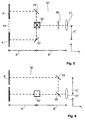
- Figs. 5 and 6 show the optical system 50 for combining the light beams coming from the active light modulators 4, 6, 8.
- the light modulators are arranged in accordance with the pattern shown in Fig. 4a.
- Fig. 5 shows that part of the optical system 50 which is used for combining the light beams coming from the red and from the blue light modulator 4 and 6.
- a color-combining prism 52 and a first and a second mirror 53 and 54 are provided at a distance A from the plane 7 determined by the light modulators.
- the first mirror 53 is arranged centered in front of the red light modulator 4 at an angle of 45° with respect to the beam path.
- the second mirror 54 is arranged centered in front of the blue light modulator 6 at an angle of -45° with respect to the beam path.
- the red and the blue light modulators 4 and 6 are kept at a distance from one another by the spacing field 44.
- the color-combining prism 52 is located centered in front of the spacing field 44.
- the first and the second mirrors 53, 54 are attached accordingly such that they direct the light coming from the red and blue light modulators 4 and 6 onto the color-combining prism 52.
- Fig. 6 now shows that part of the optical system 50 that combines the light beam coming from the green light modulator 8 with the already combined light from the red and blue light modulators 4 and 6.
- a third mirror 55 is provided and deflects the light to a dichroitic mirror 56 also attached at a distance B behind the color-combining prism 52.
- the light beam from the green light modulator 8 and the already combined light beams from the red and blue light modulators 4 and 6 are combined in the beam path behind the dichroitic mirror 56.
- the third mirror 55 and the dichroitic mirror 56 are at a distance C from one another that is equal to the side length c of the light modulators 4, 6, 8.
- a projection lens 21 arranged behind the dichroitic mirror 56 projects the light beams, which have been combined without optical path length difference.
- the distances of the first and second mirrors 53 and 54 and of the color-combining prism 52 can be freely selected, with two restrictions; the first restriction is that all distances must be of equal size, and the second restriction is that the distance must be selected with due consideration of the size of the optical components. The same applies for the arrangement of the third mirror 55 and of the dichroitic mirror 56.
Landscapes
- Engineering & Computer Science (AREA)
- Multimedia (AREA)
- Signal Processing (AREA)
- Projection Apparatus (AREA)
- Mechanical Light Control Or Optical Switches (AREA)
- Devices For Indicating Variable Information By Combining Individual Elements (AREA)
Applications Claiming Priority (2)
| Application Number | Priority Date | Filing Date | Title |
|---|---|---|---|
| DE19757109 | 1997-12-20 | ||
| DE19757109A DE19757109A1 (de) | 1997-12-20 | 1997-12-20 | Digitalprojektor mit einem optischen System zum Ausgleich des optischen Weglängenunterschieds |
Publications (2)
| Publication Number | Publication Date |
|---|---|
| EP0924937A2 true EP0924937A2 (fr) | 1999-06-23 |
| EP0924937A3 EP0924937A3 (fr) | 2003-03-12 |
Family
ID=7852900
Family Applications (1)
| Application Number | Title | Priority Date | Filing Date |
|---|---|---|---|
| EP98123857A Withdrawn EP0924937A3 (fr) | 1997-12-20 | 1998-12-16 | Projecteur numérique avec système optique pour compenser la différence de longueur d'un chemin optique |
Country Status (4)
| Country | Link |
|---|---|
| US (1) | US6128125A (fr) |
| EP (1) | EP0924937A3 (fr) |
| JP (1) | JPH11265031A (fr) |
| DE (1) | DE19757109A1 (fr) |
Families Citing this family (8)
| Publication number | Priority date | Publication date | Assignee | Title |
|---|---|---|---|---|
| US6969635B2 (en) | 2000-12-07 | 2005-11-29 | Reflectivity, Inc. | Methods for depositing, releasing and packaging micro-electromechanical devices on wafer substrates |
| US6962419B2 (en) | 1998-09-24 | 2005-11-08 | Reflectivity, Inc | Micromirror elements, package for the micromirror elements, and projection system therefor |
| US7300162B2 (en) | 2000-08-30 | 2007-11-27 | Texas Instruments Incorporated | Projection display |
| US7023606B2 (en) | 2001-08-03 | 2006-04-04 | Reflectivity, Inc | Micromirror array for projection TV |
| US7042622B2 (en) | 2003-10-30 | 2006-05-09 | Reflectivity, Inc | Micromirror and post arrangements on substrates |
| US6886944B2 (en) * | 2003-05-13 | 2005-05-03 | Hewlett-Packard Development Company, L.P. | Projector brightness enhancement using rectilinear apertures |
| US7090353B1 (en) | 2004-08-14 | 2006-08-15 | Lockheed Martin Corp. | System and method for improved digital projection |
| US7188953B2 (en) * | 2005-05-03 | 2007-03-13 | Eastman Kodak Company | Display apparatus using LCD panel |
Family Cites Families (10)
| Publication number | Priority date | Publication date | Assignee | Title |
|---|---|---|---|---|
| US4368963A (en) * | 1978-06-29 | 1983-01-18 | Michael Stolov | Multicolor image or picture projecting system using electronically controlled slides |
| US4906071A (en) * | 1987-03-31 | 1990-03-06 | Matsushita Electric Industrial Co., Ltd. | Liquid crystal display device and video projector incorporating same with particular driving circuit connection scheme |
| US5185712A (en) * | 1989-06-30 | 1993-02-09 | Casio Computer Co., Ltd. | Viewfinder and image display/pickup apparatus using liquid crystal |
| IL92555A0 (en) * | 1989-12-05 | 1990-08-31 | Michael Stalow | Multilayer parallax-free liquid crystal device |
| DE69123288T2 (de) * | 1990-05-21 | 1997-04-24 | Victor Company Of Japan | Anzeigegerät |
| US5398081A (en) * | 1993-06-07 | 1995-03-14 | Raychem Corporation | Apparatus for projecting colored images |
| US5594563A (en) * | 1994-05-31 | 1997-01-14 | Honeywell Inc. | High resolution subtractive color projection system |
| JP3559107B2 (ja) * | 1995-06-19 | 2004-08-25 | 株式会社半導体エネルギー研究所 | 表示装置 |
| US5767924A (en) * | 1995-06-09 | 1998-06-16 | Semiconductor Energy Laboratory Co., | Display unit which is immersed in a coolant |
| US5632545A (en) * | 1996-07-26 | 1997-05-27 | Lextron Systems, Inc. | Enhanced video projection system |
-
1997
- 1997-12-20 DE DE19757109A patent/DE19757109A1/de not_active Withdrawn
-
1998
- 1998-12-16 EP EP98123857A patent/EP0924937A3/fr not_active Withdrawn
- 1998-12-16 US US09/212,452 patent/US6128125A/en not_active Expired - Fee Related
- 1998-12-18 JP JP10361519A patent/JPH11265031A/ja active Pending
Also Published As
| Publication number | Publication date |
|---|---|
| EP0924937A3 (fr) | 2003-03-12 |
| US6128125A (en) | 2000-10-03 |
| DE19757109A1 (de) | 1999-06-24 |
| JPH11265031A (ja) | 1999-09-28 |
Similar Documents
| Publication | Publication Date | Title |
|---|---|---|
| US5300966A (en) | Projector | |
| JP4182374B2 (ja) | 投射型表示装置 | |
| US8066389B2 (en) | Beam alignment chamber providing divergence correction | |
| US20060227418A1 (en) | Three-dimensional display method and device therefor | |
| US4054907A (en) | Back projection apparatus | |
| US20100302514A1 (en) | Beam alignment system using arrayed light sources | |
| EP0711426B1 (fr) | Dispositif de projection d'images | |
| JPH09500982A (ja) | 液晶投射表示システム | |
| JPH09507588A (ja) | カラー液晶投写形ディスプレイシステム | |
| US20110176120A1 (en) | Projection system | |
| JP2000194068A (ja) | 照明光学系および投写型表示装置 | |
| US6128125A (en) | Digital projector with an optical system for compensating the optical path length difference | |
| EP1072923B1 (fr) | Système d'illumination optique et projecteur l'utilisant | |
| US5140466A (en) | Optical multiplexer | |
| JP4050126B2 (ja) | 画像投影表示装置 | |
| US7677732B2 (en) | Stereoscopic image display apparatus | |
| US7517094B2 (en) | Projection device | |
| JP2005266765A (ja) | プロジェクタ | |
| JPH1152889A (ja) | 画像表示装置 | |
| JP2002372677A (ja) | 投影型画像表示装置及びその合波光学系 | |
| KR20230027094A (ko) | Led 조명 프로젝터 | |
| JP3684926B2 (ja) | 照明光学系及びこれを用いた投写型表示装置 | |
| US20260003255A1 (en) | Projection display | |
| CN114967309A (zh) | 投影仪 | |
| JP2001042430A (ja) | 照明光学系及びこれを用いた投写型表示装置 |
Legal Events
| Date | Code | Title | Description |
|---|---|---|---|
| PUAI | Public reference made under article 153(3) epc to a published international application that has entered the european phase |
Free format text: ORIGINAL CODE: 0009012 |
|
| AK | Designated contracting states |
Kind code of ref document: A2 Designated state(s): AT BE CH CY DE DK ES FI FR GB GR IE IT LI LU MC NL PT SE |
|
| AX | Request for extension of the european patent |
Free format text: AL;LT;LV;MK;RO;SI |
|
| PUAL | Search report despatched |
Free format text: ORIGINAL CODE: 0009013 |
|
| AK | Designated contracting states |
Kind code of ref document: A3 Designated state(s): AT BE CH CY DE DK ES FI FR GB GR IE IT LI LU MC NL PT SE Designated state(s): AT BE CH CY DE DK ES FI FR GB GR IE IT LI LU MC NL PT SE |
|
| AX | Request for extension of the european patent |
Extension state: AL LT LV MK RO SI |
|
| 17P | Request for examination filed |
Effective date: 20030812 |
|
| AKX | Designation fees paid |
Designated state(s): AT BE CH LI |
|
| REG | Reference to a national code |
Ref country code: DE Ref legal event code: 8566 |
|
| RBV | Designated contracting states (corrected) |
Designated state(s): DE FR GB |
|
| STAA | Information on the status of an ep patent application or granted ep patent |
Free format text: STATUS: THE APPLICATION IS DEEMED TO BE WITHDRAWN |
|
| 18D | Application deemed to be withdrawn |
Effective date: 20060131 |