EP0924953A2 - Verfahren und Vorrichtung für eine Datenverbindung mit wählbarer Geschwindigkeit in einem Telekommunikationssystem - Google Patents
Verfahren und Vorrichtung für eine Datenverbindung mit wählbarer Geschwindigkeit in einem Telekommunikationssystem Download PDFInfo
- Publication number
- EP0924953A2 EP0924953A2 EP19980309813 EP98309813A EP0924953A2 EP 0924953 A2 EP0924953 A2 EP 0924953A2 EP 19980309813 EP19980309813 EP 19980309813 EP 98309813 A EP98309813 A EP 98309813A EP 0924953 A2 EP0924953 A2 EP 0924953A2
- Authority
- EP
- European Patent Office
- Prior art keywords
- data
- parity
- format
- selectable
- rates
- Prior art date
- Legal status (The legal status is an assumption and is not a legal conclusion. Google has not performed a legal analysis and makes no representation as to the accuracy of the status listed.)
- Withdrawn
Links
- 238000000034 method Methods 0.000 title abstract description 11
- 239000004744 fabric Substances 0.000 claims abstract description 22
- 238000013500 data storage Methods 0.000 claims description 4
- 101800000628 PDH precursor-related peptide Proteins 0.000 description 15
- PQGCEDQWHSBAJP-TXICZTDVSA-N 5-O-phosphono-alpha-D-ribofuranosyl diphosphate Chemical compound O[C@H]1[C@@H](O)[C@@H](O[P@](O)(=O)OP(O)(O)=O)O[C@@H]1COP(O)(O)=O PQGCEDQWHSBAJP-TXICZTDVSA-N 0.000 description 13
- 230000006870 function Effects 0.000 description 7
- 238000010586 diagram Methods 0.000 description 4
- 230000005540 biological transmission Effects 0.000 description 2
- 239000002131 composite material Substances 0.000 description 1
- 238000005516 engineering process Methods 0.000 description 1
- 238000011144 upstream manufacturing Methods 0.000 description 1
- 239000002699 waste material Substances 0.000 description 1
Images


Classifications
-
- H—ELECTRICITY
- H04—ELECTRIC COMMUNICATION TECHNIQUE
- H04Q—SELECTING
- H04Q11/00—Selecting arrangements for multiplex systems
- H04Q11/04—Selecting arrangements for multiplex systems for time-division multiplexing
- H04Q11/0428—Integrated services digital network, i.e. systems for transmission of different types of digitised signals, e.g. speech, data, telecentral, television signals
- H04Q11/0478—Provisions for broadband connections
Definitions
- the invention relates to transmission of data and more particularly to a method and apparatus for transmission of packets of switched data from a high speed trunk to a lower speed data line.
- a high speed data trunk communicates with multiple data lines of lesser speed by means of a switch fabric.
- a high speed trunk 101 operates at 65 megabits per second and carries data in 768 time slots.
- Each of the multiple data links to lines 106 0 - 106 N connects to interface module 104.
- the time slot data coming from the fabric 102 to the interface module 104 is in parallel format, which provides a very high data rate.
- the data rate of the interface module 104 is at the lower speed of 4 mega bits per second.
- an interface module that has selectable higher data rates.
- an interface module apparatus including a receiving portion and a transmitting portion.
- the transmitting portion has multiple parity checkers with each parity checker checking parity on a per time slot basis. Also, the receiving portion and the transmitting portion have selectable data rates.
- an interface module apparatus for communicating data from a switch fabric to N+1 data links.
- the interface module apparatus has a receiving portion which receives data from the switch fabric in parallel format and outputs data in serial format.
- the interface module apparatus also has a transmitting portion which has a multiple parity checkers with each parity checker checking parity on a per time slot basis. Both the receiving portion and the transmitting portion have selectable data rates
- FIG. 1 is a block diagram illustration of a known telecommunication switch system communicating with fixed speed data lines.
- FIG. 2 is a block diagram illustration of a telecommunication switch communicating with data lines having selectable speeds.
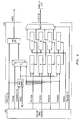
- FIG. 3 is a block diagram of a protocol handler used to receive data for selectable speed data lines.
- FIG. 4 is a block diagram of a protocol handler used to transmit data from selectable speed data lines.
- the telecommunications switch 200 has a high speed data trunk 201 connected to a switch fabric 202, which communicates data to and from the trunk 201 in multiple time slots.
- the switch fabric 202 may be any of many networks such as a space multiplex network, a multiple stage, multiple node network and a time slot interchanger (TSI) network.
- TSI time slot interchanger
- fabric 202 is a TSI.
- the fabric 202 communicates via a parallel bus along a back plane (not shown) to multiple interface module 204.
- the interface module 204 has multiple ports to which data links 206 0 - 206 N are connected.
- the data links 206 0 - 206 N are connected to protocol handlers 210 0 - 210 N , which are also known as processors.
- the selectable data speed through interface module 204 allows the data links 206 0 -206 N to operate at least three selectable data rates. In a preferred embodiment, these rates are 4, 8 and 16 mega bits per second.
- the interface module 204 connects to separate receive and transmit circuits, as will be explained further, and therefore the data links 206 0 - 206 N are bi-directional.
- the receive portion which is defined as the data direction from the fabric to the protocol handlers 210 0 - 210 N , of the interface module 204 is shown.
- the receive portion is referred to as the protocol handler receive port processor or PRPP 302.
- each PRPP 302 there are 16 PRPPs 302 which correspond to the 16 PHDB port interfaces supported by the interface module, but for simplicity only one is shown in FIG. 3.
- the PRPPs process data only in the receive direction.
- Separate corresponding Transmit Port Processors, PTPP 402 are used to process data in the transmit direction, which are shown in FIG. 4 and will be discussed later.
- the function of each PRPP 302 is to manage the flow of parallel data received from the fabric 202 while converting it from parallel data bits to a serial bit interleaved format at the selected programmed data rate.
- the PRPP 302 can be broken down into two functional sub-sections; one that is used for data storage, and a second section that provides a data processing function.
- Data processing includes bit interleaving of 1/4, 1/2, or all of the received time slot data depending upon the rate programmed for a particular interface module and parity generation. Bit interleaving of a given set of time-slots requires that the whole set be made available when the first bit of the inter-leaved set is to be transmitted.
- One aspect of this embodiment is the large amount of temporary storage required.
- the receive fabric core always runs at the maximum 16 MHz rate supplying 128 time-slots of data to each PRPP 302 per 125 microsec frame regardless of the per port programmed rate.
- RTC receive timing control
- register A is filled for each of the 16 PRPP blocks, followed by register B for each of the 16 PRPP blocks is and so on until all four registers (A-D), of all 16 PRPP blocks, have been supplied with data.
- all 4 registers, of each PRPP block are transferred to their respective prime register A' through D' at the same time and the loading of registers A through D continues for the next group of 4 time-slots per each PRPP 302.
- the outputs of registers A' - D' are being shifted out at a 4 MHz rate and are processed by the Data Processor Section. Odd parity is generated over bits 0 - 14 of the time-slot in this section.
- a pulse is received on PRPGEN, coincident with the PRSHFT4 pulse, marking the current bit as bit 15. At this point the calculated parity is passed to the MUX 310 to be sent out on PHRCV 350.
- the Data Processor section also implements a multiplexing function, based upon the programmed rate, using one of three different rate clock enable signals (4, 8 and 16 MHz) available to the PRPP 302 for use in the final stage of clocked output. Up until this final stage, all circuitry and therefore the control signals controlling it, function in the same way and at the same frequency regardless of the programmed rate of the receive port. A selection is also made in the Data Processor section of an appropriate clock for the port in question based on the programmed rate.
- the MUX 310 shown in FIG. 3 has a selector field that cycles at the maximum 16 MHz rate regardless of the software programmed rate for a given port, rate of multiplexing is controlled by the frequency of the clock enable signal used in the final stage of output.
- a clock enable of 16 MHz results in the bit interleaved multiplexing of all four 4 MHz serial bit-streams received from the data storage section into a single 16 MHz serial output bit-stream.
- a clock enable of 8 MHz results in the bit interleaved multiplexing of two (register A' and C'), 4 MHz serial bit-streams received from the data storage section into a single 8 MHz serial output bit-stream.
- a clock enable of MHz results in the selection of one (register A') 4 MHz serial bit-stream to be passed through to the PRPP output 350.
- Locating the PRPP personality selections as close to the outer edges of each interface module 204 as is possible reduces the amount of logic required to operate in more than one mode and therefore reduces its over-all complexity.
- each PTPP 402 processes data only in the transmit direction.
- the function of each PTPP 402 is to manage the flow of serial bit interleaved data from a protocol handler on one of the data links 206 0 -206 N while converting it to a 16 bit parallel format before being passed on to the Transmit portion of the fabric 202.
- the PTPP 402 can be broken down into two functional sub-sections: Data Sample and Data Processing.
- the Data Sample sections performs the initial clocked sample on data as it enters the interface module 204. Because received data can appear at one of three different rates, 3 different transmit clock enable signals, at three different frequencies (4 MHz, 8 MHz, and 16 MHz), are available to choose from based on the state of PRCTL[1:0]. Each enable signal is one 32 MHz clock cycle in width and all are positioned for full edge transfer.
- the data processing section of PTPP 402 includes both the de-multiplexing/de-interleave and the parity checking functions.
- the interleave sub-circuit functions at the maximum 16 MHz rate regardless of the programmed rate of the port.
- PTPP registers A - D are loaded at a 4 MHz rate directed by four individual clock enable signals that are offset from each other by a single 16 MHz clock cycle.
- each register samples one of the four unique imbedded 4 MHz data streams.
- registers A and B receive one of them and register C and D the other.
- all four registers (A - D) receive the same data stream.
- the Transmit time-slot select RAM (not shown) should be initialized such that the additional time-slots connect to alternate sink locations so they do not waste a network side connection.
- registers A - D for all 16 PTPPs have shifted in 16 bits of time-slot aligned data, their contents are copied to their prime register via signal TXFREN and the shifting process is repeated.
- registers A' - D' are being transferred, in parallel format, to the transmit portion of the switch fabric 202 (not shown in FIG. 4).
- TTC transmit timing control
- register A' of all PTPPs 402 are read first, followed by register B' of all PTPPs, and so on until all registers of all PTPPs have been read.
- the cycle time for each of these processes is 3.906 microsec.
- Parity checking is performed on a per time-slot basis by four independent serial parity checkers that operate at 4 MHz on groups of 32 time-slots.
- the output of the parity checkers are OR'ed together such that any one parity checker circuit can cause the composite PTPP error output (PTPE) to activate.
- PTPE composite PTPP error output
- a PTPP error output is activated, a corresponding bit in the PPESR will be set.
- all four parity checkers sample (and check) independent data streams. In reduced bandwidth scenarios (4 and 8 MHz), some parity checkers sample (and check) the same data stream, but this is not seen as a disadvantage. Rather, it would take more logic to keep it from happening and in reduced bandwidth scenarios therefore a voting scheme is provided for parity checking.
Landscapes
- Engineering & Computer Science (AREA)
- Computer Networks & Wireless Communication (AREA)
- Detection And Prevention Of Errors In Transmission (AREA)
- Time-Division Multiplex Systems (AREA)
- Communication Control (AREA)
Applications Claiming Priority (2)
| Application Number | Priority Date | Filing Date | Title |
|---|---|---|---|
| US99179697A | 1997-12-16 | 1997-12-16 | |
| US991796 | 1997-12-16 |
Publications (1)
| Publication Number | Publication Date |
|---|---|
| EP0924953A2 true EP0924953A2 (de) | 1999-06-23 |
Family
ID=25537576
Family Applications (1)
| Application Number | Title | Priority Date | Filing Date |
|---|---|---|---|
| EP19980309813 Withdrawn EP0924953A2 (de) | 1997-12-16 | 1998-12-01 | Verfahren und Vorrichtung für eine Datenverbindung mit wählbarer Geschwindigkeit in einem Telekommunikationssystem |
Country Status (2)
| Country | Link |
|---|---|
| EP (1) | EP0924953A2 (de) |
| JP (1) | JPH11275043A (de) |
Families Citing this family (1)
| Publication number | Priority date | Publication date | Assignee | Title |
|---|---|---|---|---|
| CN101609297B (zh) | 2008-06-18 | 2011-11-30 | 珠海天威技术开发有限公司 | 打印耗材芯片数据传送的同步方法 |
-
1998
- 1998-12-01 EP EP19980309813 patent/EP0924953A2/de not_active Withdrawn
- 1998-12-16 JP JP10357110A patent/JPH11275043A/ja active Pending
Also Published As
| Publication number | Publication date |
|---|---|
| JPH11275043A (ja) | 1999-10-08 |
Similar Documents
| Publication | Publication Date | Title |
|---|---|---|
| EP0174998B1 (de) | Multiplexverbindung von gruppen von paketvermittlungsknoten | |
| US5425022A (en) | Data switching nodes | |
| US6628621B1 (en) | Multichannel-capable bit error rate test system | |
| US5691984A (en) | Compact, adaptable brouting switch | |
| US6064670A (en) | Matrix for switching between two multiplex groups | |
| CA2345537A1 (en) | A routing arrangement | |
| EP0806100B1 (de) | Reorganisationsvorrichtung zur neugruppierung von telekommunikationssignalen | |
| US7468988B2 (en) | Methods and systems for improving utilization of high-speed time division multiplexed communications links at signal transfer point | |
| US4546470A (en) | Communications systems | |
| US7457285B1 (en) | TDM switching system and ASIC device | |
| US6427179B1 (en) | System and method for protocol conversion in a communications system | |
| EP0924953A2 (de) | Verfahren und Vorrichtung für eine Datenverbindung mit wählbarer Geschwindigkeit in einem Telekommunikationssystem | |
| EP0723723B1 (de) | Signalempfangs- und signalsende - einheit | |
| EP0170799B1 (de) | Vermittlungssysteme | |
| EP0477242B1 (de) | Datenvermittlungsknoten | |
| US6625177B1 (en) | Circuit, method and/or architecture for improving the performance of a serial communication link | |
| US6628656B1 (en) | Circuit, method and/or architecture for improving the performance of a serial communication link | |
| EP0351959A2 (de) | Vielfachkanalsteuerung | |
| JP3046118B2 (ja) | 時分割通話路方式 | |
| JPS6139661A (ja) | 回線編集装置 | |
| EP0950336A2 (de) | Verfahren und vorrichtung zum verbinden von wenigstens zwei rangierverteilern in ein einziges pcm-netz | |
| JPH04362818A (ja) | 伝送路インターフェイス方式 | |
| JPH0477154A (ja) | 並列データ伝送方式 |
Legal Events
| Date | Code | Title | Description |
|---|---|---|---|
| PUAI | Public reference made under article 153(3) epc to a published international application that has entered the european phase |
Free format text: ORIGINAL CODE: 0009012 |
|
| 17P | Request for examination filed |
Effective date: 19981216 |
|
| AK | Designated contracting states |
Kind code of ref document: A2 Designated state(s): AT BE CH CY DE DK ES FI FR GB GR IE IT LI LU MC NL PT SE |
|
| AX | Request for extension of the european patent |
Free format text: AL;LT;LV;MK;RO;SI |
|
| STAA | Information on the status of an ep patent application or granted ep patent |
Free format text: STATUS: THE APPLICATION HAS BEEN WITHDRAWN |
|
| 18W | Application withdrawn |
Withdrawal date: 20010731 |