EP0925089B1 - Accouplements pour canules medicales - Google Patents
Accouplements pour canules medicales Download PDFInfo
- Publication number
- EP0925089B1 EP0925089B1 EP97931951A EP97931951A EP0925089B1 EP 0925089 B1 EP0925089 B1 EP 0925089B1 EP 97931951 A EP97931951 A EP 97931951A EP 97931951 A EP97931951 A EP 97931951A EP 0925089 B1 EP0925089 B1 EP 0925089B1
- Authority
- EP
- European Patent Office
- Prior art keywords
- coupling according
- sleeve
- valve
- slide
- casing
- Prior art date
- Legal status (The legal status is an assumption and is not a legal conclusion. Google has not performed a legal analysis and makes no representation as to the accuracy of the status listed.)
- Expired - Lifetime
Links
- 230000008878 coupling Effects 0.000 title claims abstract description 49
- 238000010168 coupling process Methods 0.000 title claims abstract description 49
- 238000005859 coupling reaction Methods 0.000 title claims abstract description 49
- 238000004891 communication Methods 0.000 description 3
- 239000012530 fluid Substances 0.000 description 3
- 230000000295 complement effect Effects 0.000 description 2
- 238000010276 construction Methods 0.000 description 2
- 238000011109 contamination Methods 0.000 description 2
- 208000015181 infectious disease Diseases 0.000 description 2
- 206010001526 Air embolism Diseases 0.000 description 1
- 241000894006 Bacteria Species 0.000 description 1
- 208000034309 Bacterial disease carrier Diseases 0.000 description 1
- 238000006073 displacement reaction Methods 0.000 description 1
- 230000009977 dual effect Effects 0.000 description 1
- 239000007788 liquid Substances 0.000 description 1
- 239000002991 molded plastic Substances 0.000 description 1
- 238000000465 moulding Methods 0.000 description 1
- 230000000284 resting effect Effects 0.000 description 1
- 238000007789 sealing Methods 0.000 description 1
- 238000000926 separation method Methods 0.000 description 1
Images

Classifications
-
- A—HUMAN NECESSITIES
- A61—MEDICAL OR VETERINARY SCIENCE; HYGIENE
- A61M—DEVICES FOR INTRODUCING MEDIA INTO, OR ONTO, THE BODY; DEVICES FOR TRANSDUCING BODY MEDIA OR FOR TAKING MEDIA FROM THE BODY; DEVICES FOR PRODUCING OR ENDING SLEEP OR STUPOR
- A61M39/00—Tubes, tube connectors, tube couplings, valves, access sites or the like, specially adapted for medical use
- A61M39/10—Tube connectors; Tube couplings
- A61M39/16—Tube connectors; Tube couplings having provision for disinfection or sterilisation
- A61M39/165—Shrouds or protectors for aseptically enclosing the connector
-
- A—HUMAN NECESSITIES
- A61—MEDICAL OR VETERINARY SCIENCE; HYGIENE
- A61M—DEVICES FOR INTRODUCING MEDIA INTO, OR ONTO, THE BODY; DEVICES FOR TRANSDUCING BODY MEDIA OR FOR TAKING MEDIA FROM THE BODY; DEVICES FOR PRODUCING OR ENDING SLEEP OR STUPOR
- A61M39/00—Tubes, tube connectors, tube couplings, valves, access sites or the like, specially adapted for medical use
- A61M39/10—Tube connectors; Tube couplings
- A61M39/1011—Locking means for securing connection; Additional tamper safeties
-
- A—HUMAN NECESSITIES
- A61—MEDICAL OR VETERINARY SCIENCE; HYGIENE
- A61M—DEVICES FOR INTRODUCING MEDIA INTO, OR ONTO, THE BODY; DEVICES FOR TRANSDUCING BODY MEDIA OR FOR TAKING MEDIA FROM THE BODY; DEVICES FOR PRODUCING OR ENDING SLEEP OR STUPOR
- A61M39/00—Tubes, tube connectors, tube couplings, valves, access sites or the like, specially adapted for medical use
- A61M39/22—Valves or arrangement of valves
- A61M39/26—Valves closing automatically on disconnecting the line and opening on reconnection thereof
-
- A—HUMAN NECESSITIES
- A61—MEDICAL OR VETERINARY SCIENCE; HYGIENE
- A61M—DEVICES FOR INTRODUCING MEDIA INTO, OR ONTO, THE BODY; DEVICES FOR TRANSDUCING BODY MEDIA OR FOR TAKING MEDIA FROM THE BODY; DEVICES FOR PRODUCING OR ENDING SLEEP OR STUPOR
- A61M39/00—Tubes, tube connectors, tube couplings, valves, access sites or the like, specially adapted for medical use
- A61M39/10—Tube connectors; Tube couplings
- A61M2039/1027—Quick-acting type connectors
-
- A—HUMAN NECESSITIES
- A61—MEDICAL OR VETERINARY SCIENCE; HYGIENE
- A61M—DEVICES FOR INTRODUCING MEDIA INTO, OR ONTO, THE BODY; DEVICES FOR TRANSDUCING BODY MEDIA OR FOR TAKING MEDIA FROM THE BODY; DEVICES FOR PRODUCING OR ENDING SLEEP OR STUPOR
- A61M39/00—Tubes, tube connectors, tube couplings, valves, access sites or the like, specially adapted for medical use
- A61M39/10—Tube connectors; Tube couplings
- A61M2039/1066—Tube connectors; Tube couplings having protection means, e.g. sliding sleeve to protect connector itself, shrouds to protect a needle present in the connector, protective housing, isolating sheath
-
- A—HUMAN NECESSITIES
- A61—MEDICAL OR VETERINARY SCIENCE; HYGIENE
- A61M—DEVICES FOR INTRODUCING MEDIA INTO, OR ONTO, THE BODY; DEVICES FOR TRANSDUCING BODY MEDIA OR FOR TAKING MEDIA FROM THE BODY; DEVICES FOR PRODUCING OR ENDING SLEEP OR STUPOR
- A61M39/00—Tubes, tube connectors, tube couplings, valves, access sites or the like, specially adapted for medical use
- A61M39/22—Valves or arrangement of valves
- A61M39/28—Clamping means for squeezing flexible tubes, e.g. roller clamps
- A61M39/286—Wedge clamps, e.g. roller clamps with inclined guides
-
- Y—GENERAL TAGGING OF NEW TECHNOLOGICAL DEVELOPMENTS; GENERAL TAGGING OF CROSS-SECTIONAL TECHNOLOGIES SPANNING OVER SEVERAL SECTIONS OF THE IPC; TECHNICAL SUBJECTS COVERED BY FORMER USPC CROSS-REFERENCE ART COLLECTIONS [XRACs] AND DIGESTS
- Y10—TECHNICAL SUBJECTS COVERED BY FORMER USPC
- Y10S—TECHNICAL SUBJECTS COVERED BY FORMER USPC CROSS-REFERENCE ART COLLECTIONS [XRACs] AND DIGESTS
- Y10S604/00—Surgery
- Y10S604/905—Aseptic connectors or couplings, e.g. frangible, piercable
Definitions
- This invention is concerned with medical catheters and cannulae, and in particular is concerned with a coupling device for connecting a cannula or catheter to a connection tube through which liquid to be administered to a patient is delivered, or fluid to be taken from a patient is collected.
- a form of coupling which has been in widespread use for many years comprises a female member fixed to the catheter end and having a moulded plastic hub defining an inwardly tapering frustoconical socket. and a male member which is fitted to the end of a connection tube forming part of an administration set for example, and which includes a tapering frustoconical spigot of complementary form to the hub socket for engaging therein with a friction fit.
- the coupling is made by pushing the male and female members together and is disconnected by pulling them apart.
- an internally threaded cap which can be screwed onto a flange provided at the free end of the hub of the female member.
- the coupling according to the invention comprises the features as defined in claim 1.
- the coupling of the invention includes a novel system for locking the male and female members against accidental separation.
- the cap is provided on the male member and has a splined sleeve, and an axially movable slide on the female member is arranged to be engageable with the sleeve to lock the sleeve, and hence the cap, against rotation relative to the hub of the female member.
- the sleeve is internally splined and the slide comprises a collar with external splines of complementary configuration and arrangement to the sleeve splines.
- the collar is preferably capable of limited rotational movement, e.g. through 10°-15°, to enable alignment between the splines of the sleeve and collar.
- the ends of the splines of the collar and/or sleeve can be shaped to guide the splines of the two parts into correct rotational alignment as the collar is moved from an unlocked to a locked position.
- the cap is locked against rotation in a direction to release the coupling by a valve actuator of the female member.
- the female part of the coupling includes a valve for closing the connection between the hub socket and the cannula tube, e.g. when there is no male part fitted to the socket.
- the valve conveniently comprises a tube section with a flexible wall enabling the tube to be collapsed by a pinching action to close the passageway through the tube.
- An element, such as a ball, for pressing on the tube can be actuated by a slider on the female coupling member.
- This slider in the preferred construction, carries the splined collar which interlocks with the sleeve fast with the cap.
- the male and female members have finger gripping sections at which the members may be held to bring the spigot and hub together and to rotationally engage the securing cap with the hub, said gripping sections being axially spaced from the hub and cap, and a casing is provided to define a sealed housing around the coupled parts of the male and female members with the gripping sections remaining outside the housing.
- an hermetically sealed enclosure can be formed around the parts with which fluids being administered to a patient may come into contact, and as the only parts which need to be handled are located outside the sealed enclosure, the risk of the enclosed parts becoming contaminated, such as by bacteria which can colonise on the surfaces, is significantly reduced.
- this device can be located on the female member so as to be housed within the casing when it is fitted to the coupling. Furthermore, the interior of the casing can be so configured that it can only be closed around the coupling if the locking collar is in its correct locking position. This means that where the locking collar is fixed to the valve actuator, the casing can be arranged so that it can not be successfully applied with the valve in a closed condition. So that the locking collar and/or valve actuator can be adjusted without need to be touched with the hand, a tool, conveniently a two pronged fork, can be provided in a sterile pack with the casing and possibly the male and/or female coupling members. The tool may serve a dual purpose in being adapted to open the sealed casing when it is desired to access the connection between the male and female members, e.g. to connect a fresh administration set.
- a tool conveniently a two pronged fork
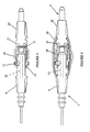
- the coupling illustrated in the drawings has a female member 1 and a male member 2.
- the female member is permanently attached in a sealed manner to a cannula tube 3, and includes a body defining a hub section 4, a valve section 5 and a finger gripping section 6.
- the finger gripping section is formed with a surface configuration, in particular longitudinal depressions 7, to facilitate firm gripping with the fingers.
- the hub section 4 has a flange 9 at its free end with screw thread elements 10, the purpose of which is described below.
- the hub includes a frustoconical socket 11 which extends inwardly from the free end of the hub.
- a short tube 12 with a flexible wall Within the valve section 5 of the body there is accommodated a short tube 12 with a flexible wall, the forward end of this tube being in communication with the cannula bore whilst the rear end of the tube is in communication with the inner end of the socket 11.
- a small ball 13 is received in a radial hole provided in the body, the ball being freely movable in this hole and resting on the exterior of the flexible tube 12. The ball 13 can be pressed inwardly to flatten the tube 12 and pinch closed the bore through the tube thereby interrupting communication between the cannula and the socket 11 of the hub, the tube 12 and ball 13 thus constituting a valve device.
- a valve actuator 15 is mounted on the body of the female member and is axially slidable thereon between a forward end position in which the valve is closed and a rear end position in which the valve is opened.
- the valve actuator 15 is annular and has an internal ramp surface arranged to cooperate with the ball 13. Internal projections on the valve actuator, conveniently located at the circumferential position of the ramp surface, are guided in a longitudinal slot or groove in the body and prevent free rotation of the valve actuator 15 on the body. However, a limited rotation of the valve actuator e.g. in the region of 10° to 15° is permitted for reasons which will be made clear.
- a flange 17 Extending around the valve actuator adjacent its forward end is a flange 17 which defines oppositely directed shoulders to facilitate adjustment of the valve actuator by means of a special purpose tool (not shown) having a bifurcated end the spacing between the prongs of the tool being slightly greater than the external diameter of the valve actuator either side of the flange whereby the prongs can be brought into abutment with either end face of the flange for effecting axial displacement of the valve actuator without need to touch the valve actuator.
- the rear end of the valve actuator has an integral collar 19 with external splines. When supplied for use the female member 1 will be in the condition shown in Figure 1, i.e. the valve being closed.
- the male member 2 can be formed essentially as a one piece moulding. It has a spigot 20 which is shaped and dimension to provide a friction sealing fit within the hub socket 11. Extending about the spigot is a cap 21 having an internal screw thread for cooperation with the threaded flange 9 of the hub 4 for securing the spigot 20 against being pulled out of the hub. Behind the cap and spigot is a finger gripping section 22 by means of which the male member 2 can be grasped in the fingers during connection of the male member to the female member of the coupling, and during their subsequent disconnection. The finger gripping section 22 is provided with depressions 7 to facilitate gripping like the gripping section of the female member.
- a circumferential groove for cooperation with an outer case as explained below.
- a sleeve 24 Integral with the forward end of the cap is a sleeve 24 with internal axial splines, e.g. in the order of 15 to 20 in number.
- the splined sleeve is adapted to cooperate with the splined collar 19 of the valve actuator 15 to lock the cap 21 against rotation relative to the female member of the coupling and hence prevent unintentional unscrewing of the cap 21 and disconnection of the coupling.
- An axial bore through the male member extends from the spigot 20 to a rear connection piece 25 by means of which the member 2 is fixedly and sealingly attached to a tube, e.g. a delivery tube of an administration set.
- the members 1,2 Holding the male and female members 1,2 by their respective finger gripping sections, the members are brought axially together so that the spigot 20 enters the hub socket 11.
- the members 1,2 are then relatively rotated to screw the cap 21 onto the hub flange 9 and to ensure that the spigot 20 is firmly and sealingly engaged in the hub socket 11, this being the condition shown in Figure 2.
- the valve actuator 15 is slid rearwardly along the body of the female member so that the splined collar 19 enters the splined sleeve 24. If the splines of the collar are not in precise alignment with the grooves between the splines of the sleeve, a small amount of rotation of the valve actuator will provide the necessary alignment.
- the leading ends of the splines on the collar 19 and the sleeve 24 are shaped to ensure a smooth and reliable engagement of the collar into the sleeve and to bring about automatically any rotation of the collar necessary to align the splines of the collar with the grooves defined between the splines of the sleeve. More particularly, the spline ends are chamfered and their lateral faces are tapered in a V-shape so that the confronting spline ends will be brought together gradually and will produce a camming action to rotate the valve actuator as necessary to obtain the rotational alignment necessary for the collar 19 to engage fully within the sleeve.
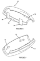
- an outer casing 30 is applied over the coupling between the finger gripping sections.
- the case as shown in Figures 5 and 6, comprises two parts 31,32 which may be separate as illustrated, but are preferably connected by an integral hinge along one edge, namely the right hand edge as viewed in the drawings.
- integral latch fingers 34 are provided in one part and have a snap engagement in slots 35 provided in the inner surface of the other part.
- the casing parts have stepped edges to improve the seal obtained when the parts are closed together around the coupled male and female members.
- a notch 36 is defined between the externally confronting edge faces, and the same tool as used for adjusting the valve actuator 15 may be inserted in this notch and twisted for opening the casing to gain access to the coupling to enable it to be disconnected if required. It may be desirable to arrange for the casing 30 to be rendered unserviceable, such as by the latch fingers becoming fractured on opening of the casing so that it becomes necessary to use a fresh sterile case.
- the valve actuator 15 can be slid forwardly, against using the tool previously described, thereby closing the valve and unlocking the cap 21 so that the male and female members may be uncoupled, if required by holding and relatively rotating the gripping sections 6,22 to release the cap 21.
- the casing 30 has inwardly directed rims at its ends, these rims being arranged so that they fit tightly around the two coupling members 1,2 adjacent but between the finger gripping sections 6,22 which remain outside the casing so that risk of contamination of the parts within the casing interior is minimised.
- the interior of the casing has protrusions 38 so positioned that. if attempt is made to fit the casing with the coupling unlocked and the valve closed the protrusions will encounter the flange 17 of the valve actuator and it will not be possible to close the casing sufficiently to engage the latch fingers 3,4.
- the invention provides a very secure coupling which if used as intended carries reduced risk of contamination of those parts at which the fluid connection is effected.
Landscapes
- Health & Medical Sciences (AREA)
- Heart & Thoracic Surgery (AREA)
- Pulmonology (AREA)
- Engineering & Computer Science (AREA)
- Anesthesiology (AREA)
- Biomedical Technology (AREA)
- Hematology (AREA)
- Life Sciences & Earth Sciences (AREA)
- Animal Behavior & Ethology (AREA)
- General Health & Medical Sciences (AREA)
- Public Health (AREA)
- Veterinary Medicine (AREA)
- Epidemiology (AREA)
- Infusion, Injection, And Reservoir Apparatuses (AREA)
- Quick-Acting Or Multi-Walled Pipe Joints (AREA)
Abstract
Claims (19)
- Un accouplement pour une canule médicale ou un cathéter comprenant un élément femelle (1) présentant une douille (11), un élément mâle (2) présentant un bout uni (20) pouvant être engagé avec un ajustement gras dans la douille (11), un capuchon (21) fixé à un élément et pouvant coopérer de manière rotative avec l'autre élément pour empêcher le bout uni de se dégager de la douille, et un agencement de blocage pour bloquer le capuchon (21) contre la rotation dans le sens du dégagement dudit autre élément, caractérisé en ce que l'agencement de blocage comprend un manchon (24) placé sur le capuchon et une coulisse (19) déplaçable sur ledit autre élément pour engager le manchon et ainsi bloquer le manchon et le capuchon contre toute rotation dans le sens du dégagement.
- Un accouplement selon la revendication 1, dans lequel la coulisse (19) et le manchon (24) peuvent s'engager par le biais d'un raccordement cannelé.
- Un accouplement selon la revendication 2, dans lequel le manchon (24) est cannelé à l'intérieur.
- Un accouplement selon la revendication 2 ou 3, dans lequel la coulisse (19) est cannelée à l'extérieur.
- Un accouplement selon la revendication 2, 3 ou 4, dans lequel la coulisse (19) est en mesure d'effectuer une rotation selon un angle limité sensiblement inférieur à une révolution complète afin d'aligner les cannelures pendant l'engagement de la coulisse (19) dans le manchon (24).
- Un accouplement selon la revendication 5, dans lequel les extrémités des cannelures sont formées de façon à entraíner automatiquement toute rotation de la coulisse (19) nécessaire pour permettre l'engagement par blocage de la coulisse (19) avec le manchon (24).
- Un accouplement selon l'une quelconque des revendications 1 à 7, dans lequel la coulisse comprend un collier cannelé (19).
- Un accouplement selon l'une quelconque des revendications 1 à 7, dans lequel le capuchon (21) et le manchon (24) sont prévus sur l'élément mâle (2) et la coulisse (19) est montée de manière déplaçable sur l'élément femelle (1).
- Un accouplement selon la revendication 8, dans lequel l'élément femelle comprend une vanne présentant un actionneur (15), la coulisse (19) étant déplaçable avec l'actionneur.
- Un accouplement selon la revendication 9, dans lequel le déplacement axial de l'actionneur (15) pour ouvrir la vanne amène la coulisse (19) en engagement avec le manchon.
- Un accouplement selon la revendication 9 ou 10, dans lequel la vanne comprend un tube à paroi souple (12) à l'intérieur d'un corps de l'élément femelle, et un élément (13) déplaçable radialement par l'actionneur (15) pour fermer le tube par pincement.
- Un accouplement selon l'une quelconque des revendications 9 à 11, dans lequel un outil séparé est fourni pour déplacer l'actionneur afin d'ouvrir la vanne sans que l'actionneur soit touché par une main.
- Un accouplement selon l'une quelconque des revendications précédentes, dans lequel les éléments mâle et femelle (1, 2) présentent des sections de préhension digitale (6, 22) auxquelles les éléments doivent être maintenus durant l'engagement du bout uni (20) dans la douille (11) et l'engagement du capuchon, et un boítier (30) est fourni pour définir un logement fermé hermétiquement autour des parties couplées des éléments mâle et femelle avec les sections de préhension (6, 22) restant à l'extérieur du logement.
- Un accouplement selon la revendication 13, dans lequel le boítier comprend deux parties (31, 32) présentant des moyens d'engagement coopérant par encliquetage (34, 35) pour fixer ensemble les parties du boítier en position fermée.
- Un accouplement selon la revendication 14, dans lequel les parties de boítier sont connectées ensemble par une charnière intégrale.
- Un accouplement selon la revendication 14 ou 15, dans lequel les moyens d'engagement par encliquetage sont agencés de façon à se casser à l'ouverture du boítier fermée afin d'empêcher la réutilisation du boítier.
- Un accouplement selon les revendications 14 à 16, dans lequel les parties du boítier présentent des bords étagés au niveau desquels les parties s'engagent de manière hermétique lorsque le boítier est fermé.
- Un accouplement selon l'une quelconque des revendications 13 à 17, dans lequel l'élément femelle comprend une vanne avec un actionneur déplaçable, et le boítier présente des moyens formant butée (38) à l'intérieur de celui-ci pour empêcher le boítier d'être fermé avec la vanne en position fermée.
- Un accouplement selon l'une quelconque des revendications 13 à 18, dans lequel le boítier présente des rebords dirigés vers l'intérieur au niveau de ses extrémités destinés à engager fermement les éléments mâle et femelle (1, 2) situés de manière adjacente mais entre les sections de préhension (6, 22).
Applications Claiming Priority (3)
| Application Number | Priority Date | Filing Date | Title |
|---|---|---|---|
| GB9615010 | 1996-07-17 | ||
| GBGB9615010.7A GB9615010D0 (en) | 1996-07-17 | 1996-07-17 | Couplings for medical cannulae |
| PCT/GB1997/001936 WO1998002206A2 (fr) | 1996-07-17 | 1997-07-16 | Accouplements pour canules medicales |
Publications (2)
| Publication Number | Publication Date |
|---|---|
| EP0925089A2 EP0925089A2 (fr) | 1999-06-30 |
| EP0925089B1 true EP0925089B1 (fr) | 2004-11-03 |
Family
ID=10797064
Family Applications (1)
| Application Number | Title | Priority Date | Filing Date |
|---|---|---|---|
| EP97931951A Expired - Lifetime EP0925089B1 (fr) | 1996-07-17 | 1997-07-16 | Accouplements pour canules medicales |
Country Status (9)
| Country | Link |
|---|---|
| US (1) | US6267754B1 (fr) |
| EP (1) | EP0925089B1 (fr) |
| JP (1) | JP2000517205A (fr) |
| CN (1) | CN1167478C (fr) |
| AU (1) | AU3553197A (fr) |
| DE (1) | DE69731476T2 (fr) |
| ES (1) | ES2235241T3 (fr) |
| GB (1) | GB9615010D0 (fr) |
| WO (1) | WO1998002206A2 (fr) |
Families Citing this family (49)
| Publication number | Priority date | Publication date | Assignee | Title |
|---|---|---|---|---|
| AU726317B2 (en) * | 1997-04-29 | 2000-11-02 | Harwill Industries (Pty) Limited | Peak flow monitor |
| GB9801261D0 (en) | 1998-01-21 | 1998-03-18 | Peters Joseph L | Couplings for medical cannulae |
| CA2314692C (fr) * | 2000-07-28 | 2009-05-19 | Ian Alexander Sloan | Raccord universel de dispositif respiratoire |
| US6916051B2 (en) * | 2003-02-13 | 2005-07-12 | Medical Components, Inc. | Coupler for a flexible tube |
| KR100940701B1 (ko) * | 2003-07-31 | 2010-02-08 | 가부시끼가이샤 제이엠에스 | 의료용 커넥터 시스템 |
| US20050251102A1 (en) * | 2003-09-26 | 2005-11-10 | Michael Hegland | Catheter connection systems and methods |
| US6910906B2 (en) * | 2003-10-31 | 2005-06-28 | Codman & Shurtleff, Inc. | Connector assembly |
| US20050137581A1 (en) * | 2003-12-17 | 2005-06-23 | Kouros Azar | Liposuction/tubing coupling for providing rotational movement |
| US7331613B2 (en) * | 2004-05-13 | 2008-02-19 | Medtronic, Inc. | Medical tubing connector assembly incorporating strain relief sleeve |
| US7497484B2 (en) * | 2004-08-11 | 2009-03-03 | Smiths Medical Asd, Inc. | Medical coupling system |
| US7537245B2 (en) * | 2005-02-14 | 2009-05-26 | Medtronic, Inc. | Strain relief device and connector assemblies incorporating same |
| EP1907045B1 (fr) | 2005-05-20 | 2014-01-08 | Medtronic, Inc. | Connecteur de verrouillage de catheter et procede |
| US8051797B1 (en) * | 2005-11-07 | 2011-11-08 | Boston Scientific Scimed, Inc. | Device to stabilize and align a pre-mounted stent |
| US20080097296A1 (en) * | 2006-08-16 | 2008-04-24 | Boston Scientific Scimed, Inc. | Removable hub assembly for medical device |
| US7758082B2 (en) * | 2006-12-05 | 2010-07-20 | Nxstage Medical, Inc. | Fluid line connector safety device |
| US7926856B2 (en) * | 2007-03-02 | 2011-04-19 | Smith & Nephew, Inc. | Fluid conduit connection |
| USD599478S1 (en) | 2007-07-10 | 2009-09-01 | Medical Components, Inc. | Adapter clamp for tubing |
| GB0724827D0 (en) * | 2007-12-20 | 2008-01-30 | Smith & Nephew | Connectors |
| EP2252342B1 (fr) * | 2008-02-14 | 2014-10-08 | Spiracur Inc. | Dispositifs et procédés de traitement de tissu endommagé |
| US20100095853A1 (en) * | 2008-10-21 | 2010-04-22 | Helen Of Troy Limited | Easy-clean food baster |
| US9078992B2 (en) | 2008-10-27 | 2015-07-14 | Pursuit Vascular, Inc. | Medical device for applying antimicrobial to proximal end of catheter |
| WO2011056582A1 (fr) | 2009-10-27 | 2011-05-12 | Nxstage Medical Inc. | Dispositif de sécurité pour conduite de fluide |
| ES2797649T3 (es) | 2011-07-12 | 2020-12-03 | Icu Medical Inc | Dispositivo para entrega de agente antimicrobiano en un catéter transdérmico |
| AU2013342123B2 (en) | 2012-11-12 | 2018-08-02 | Icu Medical, Inc. | Medical connector |
| JP6195341B2 (ja) * | 2013-03-13 | 2017-09-13 | 公立大学法人和歌山県立医科大学 | 医療用コネクタ |
| AU2015252808B2 (en) | 2014-05-02 | 2019-02-21 | Excelsior Medical Corporation | Strip package for antiseptic cap |
| USD919804S1 (en) | 2014-10-13 | 2021-05-18 | W. L. Gore & Associates, Inc. | Handle for medical delivery apparatus device |
| USD799033S1 (en) | 2015-04-02 | 2017-10-03 | W. L. Gore & Associates, Inc. | Catheter handle |
| USD790057S1 (en) | 2015-04-02 | 2017-06-20 | W. L. Gore & Associates, Inc. | Handle design for catheter Y-hub with dual side ports |
| WO2016182822A1 (fr) | 2015-05-08 | 2016-11-17 | Icu Medical, Inc. | Raccords médicaux configurés pour recevoir des émetteurs d'agents thérapeutiques |
| US10661070B2 (en) | 2015-09-14 | 2020-05-26 | The Tubieguard Llc | Bracket for feeding tube connector |
| US10369338B2 (en) * | 2016-02-23 | 2019-08-06 | Globus Medical, Inc. | Expandable tissue dilator for dilating tissue around a spinal column |
| WO2017207166A1 (fr) * | 2016-05-30 | 2017-12-07 | Fresenius Kabi Deutschland Gmbh | Raccord pour raccorder un cathéter à un système de transfert de fluide |
| EP4194043A1 (fr) | 2016-10-14 | 2023-06-14 | ICU Medical, Inc. | Capuchons désinfectants pour raccords médicaux |
| WO2018204206A2 (fr) | 2017-05-01 | 2018-11-08 | Icu Medical, Inc. | Raccords de fluide médical et procédés pour fournir des additifs dans des conduites de fluide médical |
| CN107174250A (zh) * | 2017-07-04 | 2017-09-19 | 台州亿联健医疗科技有限公司 | 一次性使用的流量传感器、传感器手柄和肺功能分析系统 |
| US11517732B2 (en) | 2018-11-07 | 2022-12-06 | Icu Medical, Inc. | Syringe with antimicrobial properties |
| US11534595B2 (en) | 2018-11-07 | 2022-12-27 | Icu Medical, Inc. | Device for delivering an antimicrobial composition into an infusion device |
| US11400195B2 (en) | 2018-11-07 | 2022-08-02 | Icu Medical, Inc. | Peritoneal dialysis transfer set with antimicrobial properties |
| US11541220B2 (en) | 2018-11-07 | 2023-01-03 | Icu Medical, Inc. | Needleless connector with antimicrobial properties |
| US11541221B2 (en) | 2018-11-07 | 2023-01-03 | Icu Medical, Inc. | Tubing set with antimicrobial properties |
| AU2019384564B2 (en) | 2018-11-21 | 2023-11-23 | Icu Medical, Inc. | Antimicrobial device comprising a cap with ring and insert |
| US11873161B2 (en) | 2020-04-30 | 2024-01-16 | Rubbermaid Commercial Products Llc | Waste receptacles |
| USD952981S1 (en) | 2020-04-30 | 2022-05-24 | Rubbermaid Commercial Products Llc | Waste receptacle with a handle |
| JP2024500319A (ja) | 2020-12-07 | 2024-01-09 | アイシーユー・メディカル・インコーポレーテッド | 腹膜透析キャップ、システム、及び方法 |
| JP7626367B2 (ja) | 2020-12-22 | 2025-02-04 | 株式会社Ibs | 継手および継手セット |
| WO2023091291A1 (fr) * | 2021-11-16 | 2023-05-25 | Fresenius Medical Care Holdings, Inc. | Raccords de fluide auto-obturants |
| CN114246997B (zh) * | 2021-12-30 | 2023-11-10 | 中国人民解放军陆军军医大学第二附属医院 | 一种加强密封性的负压引流管连接装置 |
| US11850342B2 (en) | 2022-03-21 | 2023-12-26 | Fresenius Medical Care Holdings, Inc. | Securing connections to dialyzers |
Family Cites Families (12)
| Publication number | Priority date | Publication date | Assignee | Title |
|---|---|---|---|---|
| US3395934A (en) * | 1965-10-22 | 1968-08-06 | Rosan Jose | Fittings for high pressure fluid lines |
| DE2949865C2 (de) * | 1979-12-12 | 1985-04-18 | B. Braun Melsungen Ag, 3508 Melsungen | Schlauchverbindung für medizinische Geräte |
| US4340052A (en) * | 1980-10-07 | 1982-07-20 | Baxter Travenol Laboratories, Inc. | Connection site protector |
| US4405312A (en) * | 1981-08-31 | 1983-09-20 | Abbott Laboratories | Connecting device for medical liquid containers |
| US4473369A (en) * | 1982-01-11 | 1984-09-25 | Baxter Travenol Laboratories, Inc. | Continuous ambulatory peritoneal dialysis clamping system |
| US5094491A (en) * | 1989-10-31 | 1992-03-10 | Vsi Corporation | Hydraulic fitting nut lock |
| US5037405A (en) * | 1990-02-06 | 1991-08-06 | Crosby Sue A | Intravenous tubing connector lock |
| DE4318101A1 (de) * | 1993-06-01 | 1994-12-08 | Sterimed Gmbh | Schlauchkupplung |
| DE4322868A1 (de) * | 1993-07-09 | 1995-01-12 | Sterimed Gmbh | Bajonett-Schlauchverbinder |
| GB9403021D0 (en) | 1994-02-17 | 1994-04-06 | Clinical Product Dev Ltd | Couplings for medical cannulae |
| US5545152A (en) * | 1994-10-28 | 1996-08-13 | Minimed Inc. | Quick-connect coupling for a medication infusion system |
| US5531695A (en) * | 1994-12-22 | 1996-07-02 | Sherwood Medical Company | Tamper evident sleeve |
-
1996
- 1996-07-17 GB GBGB9615010.7A patent/GB9615010D0/en active Pending
-
1997
- 1997-07-16 US US09/214,831 patent/US6267754B1/en not_active Expired - Fee Related
- 1997-07-16 ES ES97931951T patent/ES2235241T3/es not_active Expired - Lifetime
- 1997-07-16 WO PCT/GB1997/001936 patent/WO1998002206A2/fr not_active Ceased
- 1997-07-16 EP EP97931951A patent/EP0925089B1/fr not_active Expired - Lifetime
- 1997-07-16 CN CNB971978387A patent/CN1167478C/zh not_active Expired - Fee Related
- 1997-07-16 DE DE69731476T patent/DE69731476T2/de not_active Expired - Fee Related
- 1997-07-16 JP JP10505764A patent/JP2000517205A/ja active Pending
- 1997-07-16 AU AU35531/97A patent/AU3553197A/en not_active Abandoned
Also Published As
| Publication number | Publication date |
|---|---|
| WO1998002206A3 (fr) | 1998-04-30 |
| AU3553197A (en) | 1998-02-09 |
| US6267754B1 (en) | 2001-07-31 |
| DE69731476D1 (de) | 2004-12-09 |
| GB9615010D0 (en) | 1996-09-04 |
| WO1998002206A2 (fr) | 1998-01-22 |
| DE69731476T2 (de) | 2005-03-17 |
| ES2235241T3 (es) | 2005-07-01 |
| CN1167478C (zh) | 2004-09-22 |
| JP2000517205A (ja) | 2000-12-26 |
| EP0925089A2 (fr) | 1999-06-30 |
| CN1230128A (zh) | 1999-09-29 |
Similar Documents
| Publication | Publication Date | Title |
|---|---|---|
| US6267754B1 (en) | Couplings for medical cannulae | |
| EP1049514B1 (fr) | Raccord pour canule médicale | |
| US5830195A (en) | Couplings for medical cannulae | |
| US6217564B1 (en) | Couplings for medical cannulae | |
| EP0869826B1 (fr) | Système Luer-lock | |
| EP2224157B1 (fr) | Améliorations portant sur ou en relation avec les couplages de tube | |
| US7503596B2 (en) | Locking luer fitting | |
| US5047021A (en) | Male luer lock medical fitting | |
| US6032926A (en) | Hose coupling for a medical transfer system | |
| US8636688B2 (en) | Universal syringe with retractable needle | |
| EP3062851B1 (fr) | Raccord de cathéter | |
| CA2027846A1 (fr) | Raccord en "y" pour attache selective a l'exterieur d'une tubulure medicale | |
| EP3931458B1 (fr) | Raccord de limitation de couple | |
| EP3319682A1 (fr) | Ensemble vanne et procédés d'utilisation | |
| GB2334315A (en) | Coupling for fluids with tap | |
| WO2019096864A1 (fr) | Dispositifs de transfert de fluide | |
| CA2158744C (fr) | Collier de fixation pour connecteur de canule |
Legal Events
| Date | Code | Title | Description |
|---|---|---|---|
| PUAI | Public reference made under article 153(3) epc to a published international application that has entered the european phase |
Free format text: ORIGINAL CODE: 0009012 |
|
| 17P | Request for examination filed |
Effective date: 19990209 |
|
| AK | Designated contracting states |
Kind code of ref document: A2 Designated state(s): CH DE ES FR GB IT LI NL SE |
|
| GRAP | Despatch of communication of intention to grant a patent |
Free format text: ORIGINAL CODE: EPIDOSNIGR1 |
|
| GRAS | Grant fee paid |
Free format text: ORIGINAL CODE: EPIDOSNIGR3 |
|
| GRAA | (expected) grant |
Free format text: ORIGINAL CODE: 0009210 |
|
| AK | Designated contracting states |
Kind code of ref document: B1 Designated state(s): CH DE ES FR GB IT LI NL SE |
|
| PG25 | Lapsed in a contracting state [announced via postgrant information from national office to epo] |
Ref country code: NL Free format text: LAPSE BECAUSE OF FAILURE TO SUBMIT A TRANSLATION OF THE DESCRIPTION OR TO PAY THE FEE WITHIN THE PRESCRIBED TIME-LIMIT Effective date: 20041103 Ref country code: LI Free format text: LAPSE BECAUSE OF FAILURE TO SUBMIT A TRANSLATION OF THE DESCRIPTION OR TO PAY THE FEE WITHIN THE PRESCRIBED TIME-LIMIT Effective date: 20041103 Ref country code: CH Free format text: LAPSE BECAUSE OF FAILURE TO SUBMIT A TRANSLATION OF THE DESCRIPTION OR TO PAY THE FEE WITHIN THE PRESCRIBED TIME-LIMIT Effective date: 20041103 |
|
| REG | Reference to a national code |
Ref country code: GB Ref legal event code: FG4D |
|
| REG | Reference to a national code |
Ref country code: CH Ref legal event code: EP |
|
| REF | Corresponds to: |
Ref document number: 69731476 Country of ref document: DE Date of ref document: 20041209 Kind code of ref document: P |
|
| PG25 | Lapsed in a contracting state [announced via postgrant information from national office to epo] |
Ref country code: SE Free format text: LAPSE BECAUSE OF FAILURE TO SUBMIT A TRANSLATION OF THE DESCRIPTION OR TO PAY THE FEE WITHIN THE PRESCRIBED TIME-LIMIT Effective date: 20050203 |
|
| NLV1 | Nl: lapsed or annulled due to failure to fulfill the requirements of art. 29p and 29m of the patents act | ||
| REG | Reference to a national code |
Ref country code: CH Ref legal event code: PL |
|
| REG | Reference to a national code |
Ref country code: ES Ref legal event code: FG2A Ref document number: 2235241 Country of ref document: ES Kind code of ref document: T3 |
|
| PG25 | Lapsed in a contracting state [announced via postgrant information from national office to epo] |
Ref country code: ES Free format text: LAPSE BECAUSE OF NON-PAYMENT OF DUE FEES Effective date: 20050718 |
|
| PLBE | No opposition filed within time limit |
Free format text: ORIGINAL CODE: 0009261 |
|
| STAA | Information on the status of an ep patent application or granted ep patent |
Free format text: STATUS: NO OPPOSITION FILED WITHIN TIME LIMIT |
|
| ET | Fr: translation filed | ||
| 26N | No opposition filed |
Effective date: 20050804 |
|
| PGFP | Annual fee paid to national office [announced via postgrant information from national office to epo] |
Ref country code: DE Payment date: 20060131 Year of fee payment: 9 |
|
| PGFP | Annual fee paid to national office [announced via postgrant information from national office to epo] |
Ref country code: FR Payment date: 20060201 Year of fee payment: 9 |
|
| PGFP | Annual fee paid to national office [announced via postgrant information from national office to epo] |
Ref country code: IT Payment date: 20060731 Year of fee payment: 10 |
|
| REG | Reference to a national code |
Ref country code: ES Ref legal event code: FD2A Effective date: 20050718 |
|
| PGFP | Annual fee paid to national office [announced via postgrant information from national office to epo] |
Ref country code: GB Payment date: 20070131 Year of fee payment: 10 |
|
| PG25 | Lapsed in a contracting state [announced via postgrant information from national office to epo] |
Ref country code: DE Free format text: LAPSE BECAUSE OF NON-PAYMENT OF DUE FEES Effective date: 20070201 |
|
| REG | Reference to a national code |
Ref country code: FR Ref legal event code: ST Effective date: 20070330 |
|
| GBPC | Gb: european patent ceased through non-payment of renewal fee |
Effective date: 20070716 |
|
| PG25 | Lapsed in a contracting state [announced via postgrant information from national office to epo] |
Ref country code: FR Free format text: LAPSE BECAUSE OF NON-PAYMENT OF DUE FEES Effective date: 20060731 |
|
| PG25 | Lapsed in a contracting state [announced via postgrant information from national office to epo] |
Ref country code: GB Free format text: LAPSE BECAUSE OF NON-PAYMENT OF DUE FEES Effective date: 20070716 |
|
| PG25 | Lapsed in a contracting state [announced via postgrant information from national office to epo] |
Ref country code: IT Free format text: LAPSE BECAUSE OF NON-PAYMENT OF DUE FEES Effective date: 20070716 |