EP0925433B1 - Systeme de reglage du melange air/carburant dans un moteur a combustion interne - Google Patents
Systeme de reglage du melange air/carburant dans un moteur a combustion interne Download PDFInfo
- Publication number
- EP0925433B1 EP0925433B1 EP97928228A EP97928228A EP0925433B1 EP 0925433 B1 EP0925433 B1 EP 0925433B1 EP 97928228 A EP97928228 A EP 97928228A EP 97928228 A EP97928228 A EP 97928228A EP 0925433 B1 EP0925433 B1 EP 0925433B1
- Authority
- EP
- European Patent Office
- Prior art keywords
- lambda probe
- output signal
- probe
- lambda
- signal
- Prior art date
- Legal status (The legal status is an assumption and is not a legal conclusion. Google has not performed a legal analysis and makes no representation as to the accuracy of the status listed.)
- Expired - Lifetime
Links
Images

Classifications
-
- F—MECHANICAL ENGINEERING; LIGHTING; HEATING; WEAPONS; BLASTING
- F02—COMBUSTION ENGINES; HOT-GAS OR COMBUSTION-PRODUCT ENGINE PLANTS
- F02D—CONTROLLING COMBUSTION ENGINES
- F02D41/00—Electrical control of supply of combustible mixture or its constituents
- F02D41/02—Circuit arrangements for generating control signals
- F02D41/14—Introducing closed-loop corrections
- F02D41/1438—Introducing closed-loop corrections using means for determining characteristics of the combustion gases; Sensors therefor
- F02D41/1486—Introducing closed-loop corrections using means for determining characteristics of the combustion gases; Sensors therefor with correction for particular operating conditions
- F02D41/1487—Correcting the instantaneous control value
-
- F—MECHANICAL ENGINEERING; LIGHTING; HEATING; WEAPONS; BLASTING
- F02—COMBUSTION ENGINES; HOT-GAS OR COMBUSTION-PRODUCT ENGINE PLANTS
- F02D—CONTROLLING COMBUSTION ENGINES
- F02D41/00—Electrical control of supply of combustible mixture or its constituents
- F02D41/02—Circuit arrangements for generating control signals
- F02D41/14—Introducing closed-loop corrections
- F02D41/1438—Introducing closed-loop corrections using means for determining characteristics of the combustion gases; Sensors therefor
- F02D41/1439—Introducing closed-loop corrections using means for determining characteristics of the combustion gases; Sensors therefor characterised by the position of the sensor
- F02D41/1441—Plural sensors
-
- F—MECHANICAL ENGINEERING; LIGHTING; HEATING; WEAPONS; BLASTING
- F02—COMBUSTION ENGINES; HOT-GAS OR COMBUSTION-PRODUCT ENGINE PLANTS
- F02D—CONTROLLING COMBUSTION ENGINES
- F02D41/00—Electrical control of supply of combustible mixture or its constituents
- F02D41/02—Circuit arrangements for generating control signals
- F02D41/14—Introducing closed-loop corrections
- F02D41/1438—Introducing closed-loop corrections using means for determining characteristics of the combustion gases; Sensors therefor
- F02D41/1473—Introducing closed-loop corrections using means for determining characteristics of the combustion gases; Sensors therefor characterised by the regulation method
- F02D41/1474—Introducing closed-loop corrections using means for determining characteristics of the combustion gases; Sensors therefor characterised by the regulation method by detecting the commutation time of the sensor
Definitions
- the invention relates to a method for regulating the fuel-air ratio an internal combustion engine according to the preamble of Claim 1.
- control devices for Internal combustion engines are known in which the oxygen content in the exhaust duct is measured and evaluated (US Pat. No. 5,134,847, Patent Abstract of Japan 58-048755).
- oxygen measuring probes so-called lambda probes known, e.g. according to the principle of ion conduction by a Solid electrolytes work due to an oxygen partial pressure difference and according to the oxygen partial pressure present in the exhaust gas Output voltage signal that the transition from lack of oxygen to Excess oxygen or vice versa has a voltage jump.
- the output signal of the lambda probe is evaluated by a controller, which in turn regulates the fuel-air mixture via an actuator.
- the regulation of the fuel-air ratio primarily results in a Reduction of harmful proportions of exhaust gas emissions from internal combustion engines sought.
- From US-PS-4,796,425 is a method for controlling a fuel-air ratio known in which the probes the fuel-air ratio influenced by various correction factors. There is a Correction depending on the function of the period of the signal of the first lambda sensor.
- a regulation is known from Patent Abstracts of Japan 58-072647 which the output signal of the controller compared to the output signal of first lambda probe is delayed by a holding time.
- the hold time is thereby from the inverse ratio of the output signal of the first probe to Output signal of the second probe obtained.
- the invention has for its object to provide a method which allows an accurate and adaptable scheme, so that the Air-fuel ratio in terms of reducing exhaust emissions is further improved.
- the object is achieved in that the weighted Correction signal is a hold time through which the output signal of the Controller is delayed.
- the advantage of the invention is that it is the first lambda probe containing controlled system, a manipulated variable is superimposed by the actual duration of the output signal of the first Lambda sensor is dependent, d. H. it can correct the actual disturbance become.
- a weighting factor is the ratio of the actual measured period of the first lambda probe to the period of the first lambda probe determined at idle.
- the holding time is calculated from the comparison of the actually measured output signal of the second lambda probe with a Reference value won.
- the correction signal is formed here every turn of the lambda sensor located in front of the catalytic converter.
- the target value advantageously corresponds approximately to the mean value of the Output signal of the second lambda probe when the first lambda sensor.
- the operating point is set from the signal of the second Lambda sensor time depending on the load and speed corrected the internal combustion engine and fed to the controlled system in which the Fuel injection is adjusted.
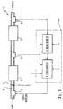
- the device consists of an internal combustion engine 1 a catalyst 2. Air is supplied to the engine 1 via an intake manifold 3.
- the fuel is injected into the intake manifold 3 via injection valves 4.
- Lambda sensors 5 and 6 measure the respective lambda value of the exhaust gas before and after the Catalyst 2. Both signals supplied by lambda sensors 5 and 6 are led to a controller with PI characteristic 8, which is usually in a control unit, not shown, is arranged in the motor vehicle.
- controller 8 uses setpoints 9 and 13 Control signal, which is fed to the injection valves 4.
- This control signal leads to a change in the fuel metering, which together with the intake air mass (air mass meter 7) one certain lambda value of the exhaust gas results.
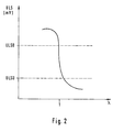
- Each lambda sensor delivers the respective fuel-air mixture representing ⁇ factor a signal curve as shown in Figure 2 is.
- the resistance or the voltage can be above the ⁇ factor to be viewed as.
- the probe If the probe is active, it has a signal voltage that is outside of the range (ULSU, ULSO). Delivers during the lean rash the lambda probe has a minimal output signal that is below ULSU lies. A maximum voltage signal appears during the fat rash measured above ULSO in a range of 600 - 800 mV. This maximum value is subject to manufacturing tolerances and signs of aging certain scatter caused by a probe correction factor Getting corrected.
- the controlled system 11 contains the injection valves 4, the engine 1, the catalytic converter 2, the lambda probe 5 and the lambda probe 6.
- the controller 8 evaluates both the 1st control loop of the lambda probe 5 (Comparison with setpoint 9) as well as the second control loop of the lambda probe 6 (comparison with setpoint 13) and produces the result described above Control signal.
- the lambda probe 6 arranged in the exhaust gas duct behind the catalytic converter 2 supplies a lambda value in the form of a signal voltage.
- This target value U 6SOLL is formed from the mean value measured by the lambda probe 6 when the lambda probe 5 arranged in front of the catalytic converter works without problems.
- a signal counter 14 with an upstream comparator 14a increments by 1 if the actual value U 6IST is greater than the target value U 6SOLL . It decrements by 1 if the actual value U 6IST is smaller than the setpoint U 6SOLL . If both values are the same, the counter reading is not changed.
- the counter 14 is arranged in front of the catalytic converter with each change Lambda probe 5 is processed and is therefore clock-controlled by this.
- the count value is multiplied by a proportionality constant in the value of (0.5 - a few 100) ms / probe change of the first lambda probe, whereby an absolute holding time TH raw is determined.
- the holding time TH raw obtained in this way is evaluated in a second multiplication point 16 with a weighting factor WF, which is determined by dividing 17 the actually measured period of the first lambda probe by a constant.
- the constant is a function of the period of the first lambda probe at idle.
- the holding time TH delays the P jump of the controller 8.
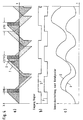
- the ⁇ control factor is plotted against time.
- the curves labeled I (dark areas in FIG. 4a) show the temporal Change in the ⁇ control factor without the influence of the second lambda sensor control loop, while the curves marked II (hatched Area in Figure 4a) the change over time of the lambda control factor, below Influence of the control loop of the lambda probe arranged behind the catalytic converter represent.
- This representation is not intended to illustrate a closed control loop, but rather only serves to illustrate the effect of the holding time TH on the first control loop.
- the holding time TH is signed, with positive times the P jump of the controller after a lean / rich probe change and negative times the P jump of the controller after a rich / lean change of the probe Decelerate the oxygen sensor located in front of the catalytic converter.
- the maximum voltage signal is subject to one Lambda probe certain spreads by a probe correction factor Getting corrected.
- the probe correction factors become independent for both lambda probes 5 and 6 determined from each other by the method described below.
- a first measuring time is started, in which the maximum probe voltage LS MAX is determined from the arithmetic mean of the measured values.
- the minimum probe voltage LS MIN is determined in a second measurement time from the arithmetic mean of the measurement values obtained during a second measurement time.
- the second measurement time follows a second settling time.
- the first and second measurement times can be the same.
- LS Cor LS MAX - LS MIN LS AMAX
- LS AMAX represents a reference value that is stored in the control electronics.
Landscapes
- Engineering & Computer Science (AREA)
- Chemical & Material Sciences (AREA)
- Combustion & Propulsion (AREA)
- Mechanical Engineering (AREA)
- General Engineering & Computer Science (AREA)
- Electrical Control Of Air Or Fuel Supplied To Internal-Combustion Engine (AREA)
- Combined Controls Of Internal Combustion Engines (AREA)
Claims (7)
- Système de régulation du mélange air/carburant dans un moteur à combustion interne, le signal de sortie d'une première sonde lambda qui est disposée dans le tuyau d'échappement du moteur à combustion interne, avant un catalyseur, étant connecté à un régulateur et le régulateur fournissant une valeur de réglage pour le mélange air/carburant et un signal de correction étant fourni au régulateur, ce signal de correction étant obtenu à partir du signal de sortie d'une seconde sonde lambda disposée après le catalyseur, le signal de correction étant pondéré en fonction de la période du signal de sortie de la première sonde lambda, caractérisé en ce que le signal de correction à pondérer est une durée d'arrêt qui décale le signal de sortie du régulateur dans le temps.
- Système selon la revendication 1, caractérisé en ce qu'un facteur de pondération est défini à partir du rapport entre la période effectivement mesurée de la première sonde lambda et la période de la première sonde lambda en roue libre.
- Système selon la revendication 1 ou 2, caractérisé en ce que la durée d'arrêt est obtenue à partir de la comparaison entre le signal de sortie effectivement mesuré de la seconde sonde lambda et une valeur de référence.
- Système selon la revendication 3, caractérisé en ce que la durée d'arrêt est formée à chaque inversion de la première sonde lambda disposée avant le catalyseur.
- Système selon la revendication 3, caractérisé en ce qu'une différence est formée à partir du signal de sortie effectivement mesuré de la seconde sonde lambda et de la valeur de référence, cette différence étant intégrée en tenant compte du signe, à l'instant de l'inversion de la première sonde de mesure du gaz carbonique, la valeur de l'intégrateur étant traduite en un temps.
- Système selon la revendication 5, caractérisé en ce que la valeur de référence représente approximativement la valeur moyenne du signal de sortie de la seconde sonde lambda lors d'un fonctionnement sans perturbation de la première sonde lambda.
- Système selon la revendication 5 ou 6, caractérisé en ce que la valeur du signal devant être fourni au régulateur dépend du point de fonctionnement du moteur à combustion interne.
Applications Claiming Priority (3)
| Application Number | Priority Date | Filing Date | Title |
|---|---|---|---|
| DE19636465A DE19636465C1 (de) | 1996-09-07 | 1996-09-07 | Verfahren zur Regelung des Kraftstoff-Luft-Verhältnisses einer Brennkraftmaschine |
| DE19636465 | 1996-09-07 | ||
| PCT/EP1997/003166 WO1998010183A1 (fr) | 1996-09-07 | 1997-06-18 | Systeme de reglage du melange air/carburant dans un moteur a combustion interne |
Publications (2)
| Publication Number | Publication Date |
|---|---|
| EP0925433A1 EP0925433A1 (fr) | 1999-06-30 |
| EP0925433B1 true EP0925433B1 (fr) | 2001-05-16 |
Family
ID=7804982
Family Applications (1)
| Application Number | Title | Priority Date | Filing Date |
|---|---|---|---|
| EP97928228A Expired - Lifetime EP0925433B1 (fr) | 1996-09-07 | 1997-06-18 | Systeme de reglage du melange air/carburant dans un moteur a combustion interne |
Country Status (5)
| Country | Link |
|---|---|
| US (1) | US6209314B1 (fr) |
| EP (1) | EP0925433B1 (fr) |
| BR (1) | BR9713196A (fr) |
| DE (2) | DE19636465C1 (fr) |
| WO (1) | WO1998010183A1 (fr) |
Families Citing this family (3)
| Publication number | Priority date | Publication date | Assignee | Title |
|---|---|---|---|---|
| DE19947364A1 (de) * | 1999-10-01 | 2001-04-12 | Volkswagen Ag | Verfahren zur Bestimmung des Abgas-Lambdawertes einer Brennkraftmaschine |
| US6380377B1 (en) | 2000-07-14 | 2002-04-30 | Applied Gene Technologies, Inc. | Nucleic acid hairpin probes and uses thereof |
| DE102004060125B4 (de) * | 2004-12-13 | 2007-11-08 | Audi Ag | Verfahren zur Steuerung der Be- und Entladung des Sauerstoffspeichers eines Abgaskatalysators |
Family Cites Families (12)
| Publication number | Priority date | Publication date | Assignee | Title |
|---|---|---|---|---|
| JPS5848755A (ja) * | 1981-09-18 | 1983-03-22 | Toyota Motor Corp | エンジンの空燃比制御方法 |
| JPS5872647A (ja) | 1981-10-26 | 1983-04-30 | Toyota Motor Corp | 内燃機関の空燃比制御方法 |
| JPS6397851A (ja) | 1986-10-13 | 1988-04-28 | Toyota Motor Corp | 内燃機関の空燃比制御装置 |
| JPH0718368B2 (ja) * | 1990-04-02 | 1995-03-06 | トヨタ自動車株式会社 | 内燃機関の触媒劣化検出装置 |
| DE4125154C2 (de) * | 1991-07-30 | 2001-02-22 | Bosch Gmbh Robert | Verfahren und Einrichtung zur Lambdasonden-Überwachung bei einer Brennkraftmaschine |
| DE4128823C2 (de) * | 1991-08-30 | 2000-06-29 | Bosch Gmbh Robert | Verfahren und Vorrichtung zum Bestimmen des Speichervermögens eines Katalysators |
| DE4139560C2 (de) * | 1991-11-30 | 2001-02-22 | Bosch Gmbh Robert | Verfahren und Vorrichtung zum Gewinnen eines Beurteilungswertes für den Alterungszustand eines Katalysators |
| JP3331650B2 (ja) * | 1992-12-28 | 2002-10-07 | スズキ株式会社 | 内燃機関の空燃比制御装置 |
| JPH06229292A (ja) * | 1993-01-29 | 1994-08-16 | Honda Motor Co Ltd | 内燃機関の空燃比制御装置 |
| JP3188579B2 (ja) * | 1994-02-15 | 2001-07-16 | 三菱電機株式会社 | 空燃比センサの故障検出装置 |
| DE19545694C2 (de) * | 1995-12-07 | 2001-07-26 | Mannesmann Vdo Ag | Verfahren zur Regelung des Kraftstoff-Luft-Verhältnisses einer Brennkraftmaschine |
| US5839274A (en) * | 1997-04-21 | 1998-11-24 | Motorola, Inc. | Method for monitoring the performance of a catalytic converter using post catalyst methane measurements |
-
1996
- 1996-09-07 DE DE19636465A patent/DE19636465C1/de not_active Expired - Fee Related
-
1997
- 1997-06-18 BR BR9713196-2A patent/BR9713196A/pt not_active IP Right Cessation
- 1997-06-18 EP EP97928228A patent/EP0925433B1/fr not_active Expired - Lifetime
- 1997-06-18 WO PCT/EP1997/003166 patent/WO1998010183A1/fr not_active Ceased
- 1997-06-18 US US09/254,053 patent/US6209314B1/en not_active Expired - Fee Related
- 1997-06-18 DE DE59703562T patent/DE59703562D1/de not_active Expired - Fee Related
Also Published As
| Publication number | Publication date |
|---|---|
| DE59703562D1 (de) | 2001-06-21 |
| EP0925433A1 (fr) | 1999-06-30 |
| WO1998010183A1 (fr) | 1998-03-12 |
| BR9713196A (pt) | 1999-11-03 |
| US6209314B1 (en) | 2001-04-03 |
| DE19636465C1 (de) | 1998-04-30 |
Similar Documents
| Publication | Publication Date | Title |
|---|---|---|
| DE102008042549B4 (de) | Verfahren und Vorrichtung zur Diagnose einer Abgassonde | |
| DE19741180B4 (de) | Motorsteuerungssystem und -Verfahren | |
| DE69410043T2 (de) | Luft-Kraftstoff-Verhältnis-Regeleinrichtung für eine Brennkraftmaschine | |
| DE3918772C2 (fr) | ||
| DE3500594A1 (de) | Zumesssystem fuer eine brennkraftmaschine zur beeinflussung des betriebsgemisches | |
| DE19545221B4 (de) | Verfahren und Vorrichtung zur Steuerung einer Brennkraftmaschine | |
| DE3311029C2 (de) | Verfahren und Vorrichtung zur Regelung der Leerlaufdrehzahl einer Brennkraftmaschine | |
| DE69015558T2 (de) | System zur Rückkopplungsregelung des Luft-/Kraftstoffverhältnisses in einer Brennkraftmaschine. | |
| DE2633617A1 (de) | Verfahren und vorrichtung zur bestimmung von einstellgroessen bei einer kraftstoffmaschine | |
| DE69634349T2 (de) | Feststellungsvorrichtung der Katalysatorverschlechterung einer Brennkraftmaschine | |
| DE3221640A1 (de) | Verfahren und vorrichtung zur optimalregelung von brennkraftmaschinen | |
| DE3732039C2 (de) | Brennstoffeinspritzungs-Steuersystem für eine Brennkraftmaschine | |
| DE19545694C2 (de) | Verfahren zur Regelung des Kraftstoff-Luft-Verhältnisses einer Brennkraftmaschine | |
| DE4238807A1 (en) | IC engine exhaust gas catalyser monitoring system - uses cross-correlation function for signals from oxygen@ sensors inserted in exhaust line before and after catalyser | |
| DE3835766A1 (de) | Elektronisches, sich anpassendes steuergeraet fuer einen verbrennungsmotor | |
| DE19545706C2 (de) | Verfahren zur Kalibrierung einer Lambdasonde in einer Brennkraftmaschine | |
| DE69006102T2 (de) | Steuergeräte zur Steuerung des Luftkraftstoffgemisches einer Brennkraftmaschine. | |
| EP1409865B1 (fr) | Procede pour equilibrer la quantite d'injection, de maniere individuelle, dans chaque cylindre d'un moteur a combustion interne | |
| DE68902373T2 (de) | Vorrichtung zur regelung des brennstoff-luft-verhaeltnisses fuer brennkraftmaschinen. | |
| EP0925433B1 (fr) | Systeme de reglage du melange air/carburant dans un moteur a combustion interne | |
| DE3744331C2 (de) | System zur Steuerung der Kraftstoffmenge einer zum Antrieb eines Fahrzeugs dienenden Brennkraftmaschine | |
| DE3729336A1 (de) | Vorrichtung zur steuerung einer brennkraftmaschine | |
| DE4235503C2 (de) | Steuersystem für das Luft-/Kraftstoffverhältnis für Verbrennungsmotoren | |
| DE3878838T2 (de) | Steuerverfahren fuer brennkraftmaschine mit verbesserten uebergangs-eigenschaften. | |
| DE19653521B4 (de) | Elektronische Steuerung einer mehrzylindrigen insbesondere fremdgezündeten Brennkraftmaschine |
Legal Events
| Date | Code | Title | Description |
|---|---|---|---|
| PUAI | Public reference made under article 153(3) epc to a published international application that has entered the european phase |
Free format text: ORIGINAL CODE: 0009012 |
|
| 17P | Request for examination filed |
Effective date: 19990119 |
|
| AK | Designated contracting states |
Kind code of ref document: A1 Designated state(s): DE FR GB IT |
|
| GRAG | Despatch of communication of intention to grant |
Free format text: ORIGINAL CODE: EPIDOS AGRA |
|
| GRAG | Despatch of communication of intention to grant |
Free format text: ORIGINAL CODE: EPIDOS AGRA |
|
| GRAH | Despatch of communication of intention to grant a patent |
Free format text: ORIGINAL CODE: EPIDOS IGRA |
|
| 17Q | First examination report despatched |
Effective date: 20001012 |
|
| GRAH | Despatch of communication of intention to grant a patent |
Free format text: ORIGINAL CODE: EPIDOS IGRA |
|
| GRAA | (expected) grant |
Free format text: ORIGINAL CODE: 0009210 |
|
| AK | Designated contracting states |
Kind code of ref document: B1 Designated state(s): DE FR GB IT |
|
| PG25 | Lapsed in a contracting state [announced via postgrant information from national office to epo] |
Ref country code: IT Free format text: LAPSE BECAUSE OF FAILURE TO SUBMIT A TRANSLATION OF THE DESCRIPTION OR TO PAY THE FEE WITHIN THE PRESCRIBED TIME-LIMIT;WARNING: LAPSES OF ITALIAN PATENTS WITH EFFECTIVE DATE BEFORE 2007 MAY HAVE OCCURRED AT ANY TIME BEFORE 2007. THE CORRECT EFFECTIVE DATE MAY BE DIFFERENT FROM THE ONE RECORDED. Effective date: 20010516 |
|
| REF | Corresponds to: |
Ref document number: 59703562 Country of ref document: DE Date of ref document: 20010621 |
|
| GBT | Gb: translation of ep patent filed (gb section 77(6)(a)/1977) |
Effective date: 20010809 |
|
| ET | Fr: translation filed | ||
| REG | Reference to a national code |
Ref country code: GB Ref legal event code: IF02 |
|
| PLBE | No opposition filed within time limit |
Free format text: ORIGINAL CODE: 0009261 |
|
| STAA | Information on the status of an ep patent application or granted ep patent |
Free format text: STATUS: NO OPPOSITION FILED WITHIN TIME LIMIT |
|
| 26N | No opposition filed | ||
| PGFP | Annual fee paid to national office [announced via postgrant information from national office to epo] |
Ref country code: GB Payment date: 20030611 Year of fee payment: 7 |
|
| PGFP | Annual fee paid to national office [announced via postgrant information from national office to epo] |
Ref country code: FR Payment date: 20030627 Year of fee payment: 7 |
|
| PGFP | Annual fee paid to national office [announced via postgrant information from national office to epo] |
Ref country code: DE Payment date: 20030818 Year of fee payment: 7 |
|
| PG25 | Lapsed in a contracting state [announced via postgrant information from national office to epo] |
Ref country code: GB Free format text: LAPSE BECAUSE OF NON-PAYMENT OF DUE FEES Effective date: 20040618 |
|
| PG25 | Lapsed in a contracting state [announced via postgrant information from national office to epo] |
Ref country code: DE Free format text: LAPSE BECAUSE OF NON-PAYMENT OF DUE FEES Effective date: 20050101 |
|
| GBPC | Gb: european patent ceased through non-payment of renewal fee |
Effective date: 20040618 |
|
| PG25 | Lapsed in a contracting state [announced via postgrant information from national office to epo] |
Ref country code: FR Free format text: LAPSE BECAUSE OF NON-PAYMENT OF DUE FEES Effective date: 20050228 |
|
| REG | Reference to a national code |
Ref country code: FR Ref legal event code: ST |