EP0925471B1 - A windbox burner - Google Patents
A windbox burner Download PDFInfo
- Publication number
- EP0925471B1 EP0925471B1 EP97939973A EP97939973A EP0925471B1 EP 0925471 B1 EP0925471 B1 EP 0925471B1 EP 97939973 A EP97939973 A EP 97939973A EP 97939973 A EP97939973 A EP 97939973A EP 0925471 B1 EP0925471 B1 EP 0925471B1
- Authority
- EP
- European Patent Office
- Prior art keywords
- ring damper
- windbox
- damper
- ring
- leaf spring
- Prior art date
- Legal status (The legal status is an assumption and is not a legal conclusion. Google has not performed a legal analysis and makes no representation as to the accuracy of the status listed.)
- Expired - Lifetime
Links
- 238000007789 sealing Methods 0.000 claims description 25
- 238000002485 combustion reaction Methods 0.000 claims description 18
- 229910000831 Steel Inorganic materials 0.000 claims description 7
- 239000010959 steel Substances 0.000 claims description 7
- 239000003779 heat-resistant material Substances 0.000 claims description 3
- 230000015572 biosynthetic process Effects 0.000 description 3
- MWUXSHHQAYIFBG-UHFFFAOYSA-N nitrogen oxide Inorganic materials O=[N] MWUXSHHQAYIFBG-UHFFFAOYSA-N 0.000 description 3
- 239000003245 coal Substances 0.000 description 2
- 238000006073 displacement reaction Methods 0.000 description 2
- 238000009434 installation Methods 0.000 description 2
- 238000004519 manufacturing process Methods 0.000 description 2
- 230000001105 regulatory effect Effects 0.000 description 2
- 230000002411 adverse Effects 0.000 description 1
- 230000001276 controlling effect Effects 0.000 description 1
- 230000000694 effects Effects 0.000 description 1
- 230000002349 favourable effect Effects 0.000 description 1
- 239000012535 impurity Substances 0.000 description 1
- 230000000717 retained effect Effects 0.000 description 1
Images



Classifications
-
- F—MECHANICAL ENGINEERING; LIGHTING; HEATING; WEAPONS; BLASTING
- F23—COMBUSTION APPARATUS; COMBUSTION PROCESSES
- F23C—METHODS OR APPARATUS FOR COMBUSTION USING FLUID FUEL OR SOLID FUEL SUSPENDED IN A CARRIER GAS OR AIR
- F23C7/00—Combustion apparatus characterised by arrangements for air supply
- F23C7/008—Flow control devices
Definitions
- the present invention relates to a windbox burner comprising a register casing with ports for inflow of combustion air, a secondary air pipe coaxial with the register casing and enclosed by it and having inlet ports for secondary air, a ring damper substantially coaxial with the register casing and axially displaceable and having at each end an annular sealing means which in the closed position of the ring damper sealingly abuts a corresponding annular sealing means at each axial end of the ports, thus preventing the combustion air from flowing through the ports to the burner tip, in which each pair of mutually abutting sealing means is made of a stainless and heat-resistant material, and in which one sealing means comprises at least one plane leaf spring the plane of which is substantially perpendicular to the longitudinal axis of the ring damper, and which in the closed position abuts on a surface of the corresponding sealing surface.
- each windbox comprises several windbox burners, each capable of containing, for example, a combined coal/oil burner.
- Coaxially with and enclosing the coal/oil burner one or more pipes are provided for supplying air to the burner tip, which air supply pipes are enclosed by a substantially tubular register casing having openings that permit combustion air from the windbox to flow into one or more of the air supply pipes.
- the air flow through the openings in the register casing is controlled by means of an axially displaceable ring damper.
- the sealing means at the ends of the air damper are usually only the roughly machined ends of the tubular ring damper abutting corresponding flanges in the register casing or a stop mounted thereon.
- Such a known ring damper may have a diameter of about 2 m, and owing to the tolerances used, a large leakage loss occurs both in the closed position of the ring damper and in its partially open position, resulting in an inadequate control of the air supply, which again may give rise to poor combustion with a consequent high NOX figure and adversely affecting the environment.
- sealing means of a stainless and heat-resistant material of which one sealing means comprises at least on plane leaf spring.
- US patent No. 3,904,349 discloses a burning apparatus in which the combustion air supplied from the windbox is distributed among three separate passageways. The quantity admitted to each passageway is controlled by separate flow regulating means.
- the object of the invention is to improve a windbox burner of the type mentioned in the introduction, in which the combustion conditions in the burner are optimized with respect to maximum reduction of the formation of NOX.
- said surface is cross-sectionally convex, the leaf spring abutting tangentially on said surface in the closed position, that the secondary air pipe supports an axially adjustable tubular damper adapted to overlapping at least a portion of each of the inlet ports and having an external collar, that in one open position the ring damper overlaps the external collar, whereby the flow of air through the space between the secondary air pipe and the register casing is substantially blocked by the external collar, and that in a second, more open position the ring damper is free of the external collar, whereby air is permitted to flow through said space as tertiary air.
- the axially adjustable tubular damper can, for example, be adjusted by means of a manually actuated screw rod or a pneumatic working cylinder receiving control impulses from the control system of the boiler or the furnace.
- the leaf spring of one sealing means has radial slits arranged equidistantly along the periphery to increase the flexibility of the leaf spring.
- the increased flexibility of the leaf spring thus obtained means that the seal can compensate for larger deviations in shape and inaccuracies in the manufacture of the ring damper and the corresponding parts of the register casing.
- one sealing means may comprise a second leaf spring abutting the first leaf spring and being substantially formed in the same way as the first leaf spring, and the slits in the two leaf springs may be mutually displaced in the tangential direction to prevent air from flowing through the slits.
- the leaf spring may be made of stainless spring band steel, and the corresponding sealing means may be a ring made of stainless round bar steel.
- the ring damper in embodiments of the windbox according to the invention may be mounted on a carriage adapted to slide on rails mounted in parallel with the centre axis of the windbox burner, or the ring damper may be mounted on a trolley with wheels adapted to run on said rails.
- the ring damper may be pivotable about an axis being substantially perpendicular to the centre axis of the windbox burner and intersecting it. It is also possible in one embodiment to let the ring damper be resiliently supported on the carriage or the trolley, which again causes the ring damper in the closed position to be able to compensate for any inaccuracies.
- the carriage or the trolley may support a fitting formed as a half-ring having at each end a pivot pin on which the ring damper is pivotably journalled, and there may be stops to limit the swinging movement of the ring damper to a swing of about ⁇ 2.5° in relation to the centre axis of the windbox burner.
- the force moving the ring damper towards its one extreme position in the swing direction may be obtained, for example, by weight-loading one end of the ring damper, by displacing the pivot pins in relation to the middle of the ring damper, or by biasing the ring damper by an elastic force.
- the ring damper is arranged inside the register casing. This has been found to entail considerable advantages, especially during dispatch and installation of windbox burners in the windbox of the boiler or furnace. Letting the ring damper be enclosed by the register casing leaves the movable parts, such as the trolley or the carriage and the ring damper itself, protected against any damage that may occur during dispatch or at the installation. If the ring damper is arranged to enclose the outside of the register casing, the ring damper with trolley or carriage must be secured so as not to move during transportation, and likewise the risk of damage to the ring damper is great, for example if the whole windbox burner is lifted in straps placed around the ring damper.
- the ports of the register casing may be formed so that the flow area in the first part of the opening movement of the ring damper increases progressively, while the flow area in the subsequent part of the movement of the ring damper increases proportionally with the axial displacement. This renders it possible to achieve a more even adjustment of the air flow over the full opening stretch of the ring damper.
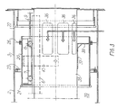
- the windbox burner is fitted into a windbox 1 and has a tubular register casing 2 with ports 3 arranged along the periphery for an inward flow of combustion air from the windbox.
- the width of the port 3 measured along the periphery of the register casing is relatively small at the end furthest away from the burner tip, while the width increases towards the burner tip.
- the register casing is closed by means of a bolted on front plate 5.
- a secondary air pipe 35 Inside the register casing and coaxially therewith is a secondary air pipe 35 having openings 36 for secondary air.
- the secondary air pipe 35 is closed at one end by means of a bolted on plate.
- a tubular ring damper 20 enclosing the secondary air pipe 35 is supported on a trolley 7 with wheels 8 running on two mutually parallel rails 6 welded on to the secondary air pipe.
- a pull rod 9 connected with, for instance, a compressed-air cylinder
- the ring damper 20 is suspended in the trolley 7 by means of a semicircular bracket 10 which is welded at the middle to the trolley by means of lugs 12 and journalled swingably about pivot pins 11 welded to the inner surface of the cylindrical wall of the ring damper.
- a semicircular bracket 10 which is welded at the middle to the trolley by means of lugs 12 and journalled swingably about pivot pins 11 welded to the inner surface of the cylindrical wall of the ring damper.
- the ring damper can swing through an angle ⁇ to either side of a starting position in which the longitudinal axis of the ring damper coincides with the centre axis of the windbox burner.
- the swings of the ring damper are limited by two stops 13 arranged on the trolley 7.
- the ring damper has a welded-on ring 21 of stainless round bar steel which, as shown in Fig. 1, abuts an annular leaf spring 23 which is retained by means of a retaining ring 25 against a flange 24 welded into the register casing 2.
- a similar annular leaf spring 26 made of stainless spring band steel which by means of a holding ring 28 is clamped on to a flange 27 welded on to the ring damper.
- the leaf spring 26 In the closing position, the leaf spring 26 abuts a ring 22 of stainless round bar steel welded on to a stop 4, which is against fixedly connected with the front plate 5 on the register casing.
- the leaf spring has radial slits 30 along its outer periphery.
- a tubular damper 37 which is longitudinally adjustable and has a collar 38 of an outer diameter so that the collar substantially blocks the space between the outer surface of the secondary air pipe 35 and the inner surface of the ring damper 20.
- the tubular damper 37 and the collar 38 are shown only in the lower half of Figs. 1, 3 and 4. It is not shown in detail how the tubular damper is adjusted axially, but this may be done, for instance, by means of a manually operated screw rod mounted in the removable front plate 5.
- the ring damper in the windbox burner according to the invention operates in the following manner: In the closed position of the ring damper, as illustrated in Fig. 1, the ring 21 at one end of the ring damper abuts the leaf spring 23, and at the same time the leaf spring 26 at the other end of the ring damper abuts the ring 22 on the stop 4. Because of the flexibility of the leaf springs good sealing is ensured between the respective sealing means, and any inaccuracies are compensated for by the ring damper having the possibility to tilt about its axis through the pivot pins 11. The combustion air supplied to the windbox 1 in a manner not shown, is thus prevented from flowing through the openings 3 in the register casing and on to the burner tip.
- the windbox burner can also be designed so that the ring damper 20 encloses the register casing 2.
- the trolley can run on rails 6 mounted on the upper surface of a secondary air pipe 35.
- the ring damper is shown in a closed position in which flow of combustion air from the windbox through the ports 3 in the register casing 2 is blocked.
- the ring damper 20 is shown in an open position in which it does not overlap the outward collar 38 on the tubular damper 37 so that as indicated by arrows both secondary air and tertiary air flows into the burner.
- the tubular damper 37 with the collar 38 is only shown in the lower part of the Figure.
Landscapes
- Engineering & Computer Science (AREA)
- Chemical & Material Sciences (AREA)
- Combustion & Propulsion (AREA)
- Mechanical Engineering (AREA)
- General Engineering & Computer Science (AREA)
- Air Supply (AREA)
- Gas Burners (AREA)
Applications Claiming Priority (3)
| Application Number | Priority Date | Filing Date | Title |
|---|---|---|---|
| DK97096 | 1996-09-09 | ||
| DK199600970A DK172645B1 (da) | 1996-09-09 | 1996-09-09 | Luftkassebrænder |
| PCT/DK1997/000374 WO1998011384A2 (en) | 1996-09-09 | 1997-09-09 | A windbox burner |
Publications (2)
| Publication Number | Publication Date |
|---|---|
| EP0925471A1 EP0925471A1 (en) | 1999-06-30 |
| EP0925471B1 true EP0925471B1 (en) | 2001-02-14 |
Family
ID=8099550
Family Applications (1)
| Application Number | Title | Priority Date | Filing Date |
|---|---|---|---|
| EP97939973A Expired - Lifetime EP0925471B1 (en) | 1996-09-09 | 1997-09-09 | A windbox burner |
Country Status (10)
| Country | Link |
|---|---|
| US (1) | US6220188B1 (da) |
| EP (1) | EP0925471B1 (da) |
| CN (1) | CN1120328C (da) |
| AU (1) | AU4199297A (da) |
| DE (1) | DE69704083T2 (da) |
| DK (2) | DK172645B1 (da) |
| ES (1) | ES2157596T3 (da) |
| PL (1) | PL332283A1 (da) |
| PT (1) | PT925471E (da) |
| WO (1) | WO1998011384A2 (da) |
Families Citing this family (6)
| Publication number | Priority date | Publication date | Assignee | Title |
|---|---|---|---|---|
| US20100081100A1 (en) * | 2008-10-01 | 2010-04-01 | Wessex Incorporated | Burner Tips |
| GB0919964D0 (en) * | 2009-11-16 | 2009-12-30 | Doosan Babcock Energy Ltd | Flow control device |
| AT520131A2 (de) * | 2017-07-13 | 2019-01-15 | Andritz Tech & Asset Man Gmbh | Verfahren zur reduktion von stickoxiden in bandbehandlungsöfen |
| CN111306301A (zh) * | 2020-03-25 | 2020-06-19 | 西安丁杰精密机械制造有限责任公司 | 一种旋片式高温高压气(液)体弹性接触动密封装置、制备方法 |
| CN112902158B (zh) * | 2021-03-01 | 2023-10-20 | 中国大唐集团科学技术研究院有限公司华中电力试验研究院 | 一种燃煤电站煤粉气流偏差调节装置及调节方法 |
| US12618555B2 (en) * | 2023-04-13 | 2026-05-05 | Honeywell International Inc. | Adjustable burner nozzle for multiple fuels |
Family Cites Families (13)
| Publication number | Priority date | Publication date | Assignee | Title |
|---|---|---|---|---|
| US598448A (en) * | 1898-02-01 | Twyer | ||
| US1213821A (en) * | 1915-07-16 | 1917-01-30 | Lars H Bergman | Pulverized-fuel burner. |
| US3443762A (en) * | 1967-01-30 | 1969-05-13 | Filipp Alexandrovich Lipinsky | Burner for liquid fuel |
| FR1561182A (da) * | 1967-12-14 | 1969-03-28 | ||
| US3904349A (en) * | 1974-05-22 | 1975-09-09 | Babcock & Wilcox Co | Fuel burner |
| GB1527072A (en) * | 1975-09-04 | 1978-10-04 | Babcock & Wilcox Ltd | Registers for fluent fuel fired burners |
| BR7706799A (pt) * | 1976-10-15 | 1978-07-11 | Benditalia Spa | Cilindro mestre hidraulico para sistema de frenagem,de veiculo |
| US4175756A (en) * | 1977-02-14 | 1979-11-27 | Garlock Inc. | Combination thrust washer and seal article, apparatus |
| US4147116A (en) * | 1977-09-19 | 1979-04-03 | Coal Tech Inc. | Pulverized coal burner for furnace and operating method |
| CA1197143A (en) * | 1980-06-04 | 1985-11-26 | Joel Vatsky | Dual register, split stream burner assembly |
| US5011400A (en) * | 1986-02-03 | 1991-04-30 | Foster Wheeler Energy Corporation | Controlled flow split steam burner assembly with sorbent injection |
| US5738021A (en) * | 1996-02-06 | 1998-04-14 | Foster Wheeler Energy International, Inc. | Adjustable sleeve damper assembly for a coal-fired furnace |
| DE19607676A1 (de) * | 1996-02-29 | 1997-09-11 | Steinmueller Gmbh L & C | Brenner und mit mindestens einem Brenner betriebene Feuerungsanlage |
-
1996
- 1996-09-09 DK DK199600970A patent/DK172645B1/da not_active IP Right Cessation
-
1997
- 1997-09-09 DK DK97939973T patent/DK0925471T3/da active
- 1997-09-09 US US09/254,487 patent/US6220188B1/en not_active Expired - Fee Related
- 1997-09-09 PL PL97332283A patent/PL332283A1/xx unknown
- 1997-09-09 EP EP97939973A patent/EP0925471B1/en not_active Expired - Lifetime
- 1997-09-09 CN CN97199255.XA patent/CN1120328C/zh not_active Expired - Fee Related
- 1997-09-09 DE DE69704083T patent/DE69704083T2/de not_active Expired - Fee Related
- 1997-09-09 WO PCT/DK1997/000374 patent/WO1998011384A2/en not_active Ceased
- 1997-09-09 ES ES97939973T patent/ES2157596T3/es not_active Expired - Lifetime
- 1997-09-09 AU AU41992/97A patent/AU4199297A/en not_active Abandoned
- 1997-09-09 PT PT97939973T patent/PT925471E/pt unknown
Also Published As
| Publication number | Publication date |
|---|---|
| PT925471E (pt) | 2001-08-30 |
| DK172645B1 (da) | 1999-03-29 |
| DE69704083T2 (de) | 2001-10-31 |
| AU4199297A (en) | 1998-04-02 |
| ES2157596T3 (es) | 2001-08-16 |
| DK97096A (da) | 1998-03-10 |
| WO1998011384A3 (en) | 1998-07-30 |
| WO1998011384A2 (en) | 1998-03-19 |
| EP0925471A1 (en) | 1999-06-30 |
| US6220188B1 (en) | 2001-04-24 |
| CN1120328C (zh) | 2003-09-03 |
| CN1235662A (zh) | 1999-11-17 |
| DE69704083D1 (de) | 2001-03-22 |
| PL332283A1 (en) | 1999-08-30 |
| DK0925471T3 (da) | 2001-06-11 |
Similar Documents
| Publication | Publication Date | Title |
|---|---|---|
| US4602571A (en) | Burner for coal slurry | |
| US8176911B2 (en) | Regulating overfire air in a boiler using an overfire air tube damper | |
| US5299512A (en) | Burner for a rotary kiln | |
| US6220188B1 (en) | Windbox burner | |
| EP0105240B1 (en) | Burner register assembly | |
| JP5332389B2 (ja) | バーナ | |
| US20100000450A1 (en) | On-line coal flow control mechanism for vertical spindle mills | |
| GB2107445A (en) | Rotary regenerative air preheater | |
| US4927352A (en) | Boiler furnace air register | |
| JP4394561B2 (ja) | 二段燃焼式ボイラ用のアフタエアノズル、および、それを用いる二段燃焼式ボイラ | |
| CA2359621C (en) | Corner windbox overfire air compartment for a fossil fuel-fired furnace | |
| CA1134255A (en) | Gas or liquid fuel burner with air register control of tangential axial combustion air movement | |
| CA1086633A (en) | Air deflector for burner | |
| US4171950A (en) | Apparatus for re-aiming a coal burner pipe in a rotary kiln | |
| JP2941716B2 (ja) | 微粉炭流量調整ダンパ | |
| CA1228796A (en) | Low pressure loss burner for coal-water slurry or fuel oil | |
| US5302115A (en) | Burner register assembly | |
| JP5021999B2 (ja) | 難燃性燃料用バーナ | |
| AU610216B2 (en) | Apparatus & method for delivery of combustion air in multiple zones | |
| US2793686A (en) | Axially adjustable fuel burner for furnaces | |
| JPH0262769B2 (da) | ||
| CN204878794U (zh) | 一种百叶窗状煤粉均衡阀 | |
| US4975045A (en) | Burner register with dual inlet air valves | |
| JPS62190311A (ja) | ラジアントチユ−ブバ−ナ | |
| JP2693211B2 (ja) | 微粉燃料バーナ |
Legal Events
| Date | Code | Title | Description |
|---|---|---|---|
| PUAI | Public reference made under article 153(3) epc to a published international application that has entered the european phase |
Free format text: ORIGINAL CODE: 0009012 |
|
| 17P | Request for examination filed |
Effective date: 19990224 |
|
| AK | Designated contracting states |
Kind code of ref document: A1 Designated state(s): DE DK ES FR GB IT PT SE |
|
| 17Q | First examination report despatched |
Effective date: 19990427 |
|
| GRAG | Despatch of communication of intention to grant |
Free format text: ORIGINAL CODE: EPIDOS AGRA |
|
| 17Q | First examination report despatched |
Effective date: 19990727 |
|
| GRAG | Despatch of communication of intention to grant |
Free format text: ORIGINAL CODE: EPIDOS AGRA |
|
| GRAH | Despatch of communication of intention to grant a patent |
Free format text: ORIGINAL CODE: EPIDOS IGRA |
|
| GRAH | Despatch of communication of intention to grant a patent |
Free format text: ORIGINAL CODE: EPIDOS IGRA |
|
| RAP1 | Party data changed (applicant data changed or rights of an application transferred) |
Owner name: FLS MILJOE A/S |
|
| GRAA | (expected) grant |
Free format text: ORIGINAL CODE: 0009210 |
|
| AK | Designated contracting states |
Kind code of ref document: B1 Designated state(s): DE DK ES FR GB IT PT SE |
|
| REF | Corresponds to: |
Ref document number: 69704083 Country of ref document: DE Date of ref document: 20010322 |
|
| ITF | It: translation for a ep patent filed | ||
| REG | Reference to a national code |
Ref country code: DK Ref legal event code: T3 |
|
| ET | Fr: translation filed | ||
| REG | Reference to a national code |
Ref country code: ES Ref legal event code: FG2A Ref document number: 2157596 Country of ref document: ES Kind code of ref document: T3 |
|
| PLBE | No opposition filed within time limit |
Free format text: ORIGINAL CODE: 0009261 |
|
| STAA | Information on the status of an ep patent application or granted ep patent |
Free format text: STATUS: NO OPPOSITION FILED WITHIN TIME LIMIT |
|
| REG | Reference to a national code |
Ref country code: GB Ref legal event code: IF02 |
|
| 26N | No opposition filed | ||
| REG | Reference to a national code |
Ref country code: GB Ref legal event code: 732E |
|
| REG | Reference to a national code |
Ref country code: FR Ref legal event code: TP Ref country code: FR Ref legal event code: CA |
|
| PGFP | Annual fee paid to national office [announced via postgrant information from national office to epo] |
Ref country code: PT Payment date: 20050916 Year of fee payment: 9 Ref country code: GB Payment date: 20050916 Year of fee payment: 9 |
|
| PGFP | Annual fee paid to national office [announced via postgrant information from national office to epo] |
Ref country code: SE Payment date: 20050919 Year of fee payment: 9 |
|
| PGFP | Annual fee paid to national office [announced via postgrant information from national office to epo] |
Ref country code: FR Payment date: 20050921 Year of fee payment: 9 Ref country code: ES Payment date: 20050921 Year of fee payment: 9 |
|
| PGFP | Annual fee paid to national office [announced via postgrant information from national office to epo] |
Ref country code: DE Payment date: 20050927 Year of fee payment: 9 |
|
| REG | Reference to a national code |
Ref country code: ES Ref legal event code: PC2A |
|
| PG25 | Lapsed in a contracting state [announced via postgrant information from national office to epo] |
Ref country code: SE Free format text: LAPSE BECAUSE OF NON-PAYMENT OF DUE FEES Effective date: 20060910 |
|
| PGFP | Annual fee paid to national office [announced via postgrant information from national office to epo] |
Ref country code: IT Payment date: 20060930 Year of fee payment: 10 |
|
| PG25 | Lapsed in a contracting state [announced via postgrant information from national office to epo] |
Ref country code: PT Free format text: LAPSE BECAUSE OF NON-PAYMENT OF DUE FEES Effective date: 20070309 |
|
| REG | Reference to a national code |
Ref country code: PT Ref legal event code: MM4A Free format text: LAPSE DUE TO NON-PAYMENT OF FEES Effective date: 20070309 |
|
| PG25 | Lapsed in a contracting state [announced via postgrant information from national office to epo] |
Ref country code: DE Free format text: LAPSE BECAUSE OF NON-PAYMENT OF DUE FEES Effective date: 20070403 |
|
| EUG | Se: european patent has lapsed | ||
| GBPC | Gb: european patent ceased through non-payment of renewal fee |
Effective date: 20060909 |
|
| REG | Reference to a national code |
Ref country code: FR Ref legal event code: ST Effective date: 20070531 |
|
| PG25 | Lapsed in a contracting state [announced via postgrant information from national office to epo] |
Ref country code: GB Free format text: LAPSE BECAUSE OF NON-PAYMENT OF DUE FEES Effective date: 20060909 |
|
| REG | Reference to a national code |
Ref country code: ES Ref legal event code: FD2A Effective date: 20060911 |
|
| PG25 | Lapsed in a contracting state [announced via postgrant information from national office to epo] |
Ref country code: ES Free format text: LAPSE BECAUSE OF NON-PAYMENT OF DUE FEES Effective date: 20060911 |
|
| PG25 | Lapsed in a contracting state [announced via postgrant information from national office to epo] |
Ref country code: FR Free format text: LAPSE BECAUSE OF NON-PAYMENT OF DUE FEES Effective date: 20061002 |
|
| PG25 | Lapsed in a contracting state [announced via postgrant information from national office to epo] |
Ref country code: IT Free format text: LAPSE BECAUSE OF NON-PAYMENT OF DUE FEES Effective date: 20070909 |
|
| PGFP | Annual fee paid to national office [announced via postgrant information from national office to epo] |
Ref country code: DK Payment date: 20160919 Year of fee payment: 20 |
|
| REG | Reference to a national code |
Ref country code: DK Ref legal event code: EUP Effective date: 20170909 |