EP0925633B1 - Verfahren und vorrichtung zum wickeln und formen von wicklungen elektrischer maschinen - Google Patents
Verfahren und vorrichtung zum wickeln und formen von wicklungen elektrischer maschinen Download PDFInfo
- Publication number
- EP0925633B1 EP0925633B1 EP97942411A EP97942411A EP0925633B1 EP 0925633 B1 EP0925633 B1 EP 0925633B1 EP 97942411 A EP97942411 A EP 97942411A EP 97942411 A EP97942411 A EP 97942411A EP 0925633 B1 EP0925633 B1 EP 0925633B1
- Authority
- EP
- European Patent Office
- Prior art keywords
- wire
- winding
- stator
- spindle
- winding spindle
- Prior art date
- Legal status (The legal status is an assumption and is not a legal conclusion. Google has not performed a legal analysis and makes no representation as to the accuracy of the status listed.)
- Expired - Lifetime
Links
Images


Classifications
-
- H—ELECTRICITY
- H02—GENERATION; CONVERSION OR DISTRIBUTION OF ELECTRIC POWER
- H02K—DYNAMO-ELECTRIC MACHINES
- H02K15/00—Processes or apparatus specially adapted for manufacturing, assembling, maintaining or repairing of dynamo-electric machines
- H02K15/08—Forming windings by laying conductors into or around core parts
- H02K15/085—Forming windings by laying conductors into or around core parts by laying conductors into slotted stators
-
- H—ELECTRICITY
- H02—GENERATION; CONVERSION OR DISTRIBUTION OF ELECTRIC POWER
- H02K—DYNAMO-ELECTRIC MACHINES
- H02K15/00—Processes or apparatus specially adapted for manufacturing, assembling, maintaining or repairing of dynamo-electric machines
- H02K15/08—Forming windings by laying conductors into or around core parts
- H02K15/095—Forming windings by laying conductors into or around core parts by laying conductors around salient poles
-
- Y—GENERAL TAGGING OF NEW TECHNOLOGICAL DEVELOPMENTS; GENERAL TAGGING OF CROSS-SECTIONAL TECHNOLOGIES SPANNING OVER SEVERAL SECTIONS OF THE IPC; TECHNICAL SUBJECTS COVERED BY FORMER USPC CROSS-REFERENCE ART COLLECTIONS [XRACs] AND DIGESTS
- Y10—TECHNICAL SUBJECTS COVERED BY FORMER USPC
- Y10T—TECHNICAL SUBJECTS COVERED BY FORMER US CLASSIFICATION
- Y10T29/00—Metal working
- Y10T29/49—Method of mechanical manufacture
- Y10T29/49002—Electrical device making
- Y10T29/49009—Dynamoelectric machine
Definitions
- the present invention relates to the formation of field windings for dynamo-electric machines and, more particularly, relates to the efficient formation of layered windings in stators having skewed slots.
- stator core formed by a plurality of stacked thin laminations of magnetically permeable material defining a central bore for receiving a rotor member of the machine.
- the stator core typically includes a plurality of slots extending radially from the central bore and defined by radially extending teeth.
- Field coils of the machine are positioned on the teeth of the stator core and are formed by insulated wire conductor wound around each of the teeth, or around predetermined groups of teeth, a predetermined number of turns.
- the field coils are generally applied to the stator by either preforming the coils and pushing them through the slots onto the stator teeth, or by winding the wire directly onto the stator teeth, which may be accomplished by a winding machine.
- Winding machines for winding wire onto stators have been used for many years and generally include a winding head mounted on the end of a shuttle and positioned in axial alignment with the bore of a stator. The shuttle is sequentially reciprocated and oscillated in a cyclic manner to move the winding head through the bore of the stator in order to position the wire for the coils in the slots of the stator.
- the wire is drawn or pulled from the winding head in response to its movement relative to the stator, and the winding head is typically provided with a radially extending needle which is adapted to properly radially position the wire within the slots and around the ends of the teeth of the stator.
- U.S. Patent No. 3,539,121 discloses a machine for winding stators with skewed slots.
- This machine is provided with a skewed cam for guiding a roller connected to the shuttle wherein the skewed cam is shaped in accordance with the slots of the stator to be wound.
- a specially shaped cam must be provided for each particular stator configuration to enable the spindle to follow the shape of the stator slots.
- an additional mechanism is required to oscillate the shuttle as it reaches the ends of the slots such that the movements of the shuttle are provided through a relatively complex combination of mechanisms.
- the positioning of the wire has in the past been relatively imprecise such that obtaining of uniform wire layers has heretofore been extremely difficult if not impossible with existing winding techniques and machinery.
- the existing techniques for winding stators having skewed slots do not permit for placement of the winding wire in a predetermined layered pattern to maximize the efficient use of the winding wire and thereby decrease the overall cost of the wound stator.
- the present invention relates to a method and apparatus for forming field coils on a stator for a dynamo-electric machine, generally of the type disclosed in US-A-3,995,785 and as a defined in the preambles of claims 1 and 9 respectively.
- the present invention provides a method and apparatus for providing stators having skewed slots with field windings.
- the apparatus embodying the invention is adapted to wind the field windings directly onto the stator, and guide the wire through the stator slot in such a manner that uniform wire layers may be formed through the winding process.
- the method of forming field coils embodying the present invention is performed by a winding machine having a winding spindle supported for rotating and reciprocating movement to direct wire into skewed slots on a stator wherein the slots are defined by radially extending teeth oriented at a predetermined skew angle.
- the winding spindle is driven in reciprocating movement by a first servo motor, and is driven in rotating or oscillating movement by a second servo motor.
- the winding spindle is supported for reciprocating movement on a slide block which is guided in vertical movement by a guide rod structure along a predetermined vertical path.
- the slide block is connected to the first servo motor through an eccentric drive rod which is driven in reciprocating movement by a main eccentric mounted for rotation on a shaft driven by the first servo motor.
- the winding spindle is connected to the second servo motor for actuation in rotating movement by a belt drive mechanism.
- the belt drive mechanism includes a toothed belt engaged around a gear concentric with and rigidly attached to the winding spindle, and driven at an opposite end by a gear having a central portion slidably engaged along a splined shaft wherein the splined shaft is driven in rotation by the second servo motor.
- Wire for winding onto the stator is driven or pushed from a wire exit, defined in a radial face of the winding spindle, radially outwardly to desired predetermined locations on the stator.
- the wire is driven through the winding spindle by a feed mechanism mounted for reciprocating movement on the slide block.
- the feed mechanism is driven by a toothed belt extending to a splined shaft rotatably driven by a third servo motor.
- the belt for the feed mechanism travels vertically along the splined shaft in response to the reciprocating vertical movement of the slide block.
- the rate at which the wire is fed from the winding spindle is controlled through a programmable controller for controlling the winding operation. Accordingly, the wire feed rate can be varied depending on the particular location of the wire exit relative to the stator during a winding cycle. In this manner, the wire may be laid in a controlled manner at desired radial positions within the stator slot throughout the movement of the winding spindle.
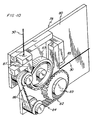
- the winding machine 10 includes a table top 12 supporting a stator nest 14 and a forming tower 16.
- the stator nest 14 includes a clamp 15 for supporting a stator 108 (illustrated in phantom lines).
- a winding spindle 18 extends upwardly through the stator support nest 14.
- the winding spindle 18 is driven in reciprocating and oscillating or rotating movement by a drive mechanism located below the table 12 in a cabinet 20.
- a programmable controller 22 is provided for selecting and controlling the winding operation.
- the programmable controller 22 includes an input panel 24 for inputting parameters for a winding operation, as well as for modifying winding operations.
- a monitor 26 is also provided for displaying information relating to the winding operation, such as the selected parameters for the winding operation, error messages and similar information for facilitating operator control of the winding process.
- the winding spindle 18 is supported on a spindle shaft 28 wherein the spindle shaft 28 is formed as a hollow tubular member for guiding an insulated wire 30 upwardly into a longitudinal passage extending through the winding spindle 18 for winding onto a stator.
- the spindle shaft 28 is supported on a slide block platform 32 which is attached to a slide block 34.
- the slide block 34 is supported for sliding movement on parallel rails 36 of a guide rod structure 35 wherein the slide block 34 is actuated for reciprocating vertical movement by an eccentric drive rod 38.
- the eccentric drive rod 38 is attached for pivotal movement to the slide block 34 at a pivot connection 40, and a lower end 42 (Fig. 2) of the drive rod 38 extends through an opening 45 in a floor 46 located within the cabinet 20 and is connected to an eccentric drive mechanism 44.
- the eccentric drive mechanism 44 is supported on the under side of the floor 46 and includes a first or longitudinal servo motor 48 controlled by the programmable controller 22.
- the first servo motor 48 drives a drive gear 50 which rotatably drives a follower gear 52 through a toothed drive belt 54.
- the follower gear 52 is mounted on a shaft 56 to drive the shaft 56 in rotating movement in response to drive inputs from the first servo motor 48.
- a main eccentric 58 is rigidly mounted to the shaft 56 and is connected to the lower end 42 of the eccentric drive rod 38.
- the lower end 42 of the drive rod 38 is connected to the main eccentric 58 through a rotatable connection, and the rotatable connection is positioned at a preselected distance from the central axis of the shaft 56 whereby rotation of the main eccentric 58 causes the drive rod 38 to move vertically in reciprocating movement.
- the attachment point between the drive rod 38 and the main eccentric 58 is adjustable wherein the lower end 42 of the drive rod 38 may be positioned at different distances from the central axis of the shaft 56 to thereby provide different stroke lengths for the reciprocating movement of the drive rod 38.
- the spindle shaft 28 is driven in rotating or oscillating movement by an oscillator servo tower 60 mounted on the floor 46.
- the oscillator servo tower 60 includes a tower frame 62 supporting a second or rotational servo motor 64 which drives a toothed belt 66 for rotating a splined shaft 68.
- the second servo motor 64 operates under control of the programmable controller 22 to precisely control the rotation of the shaft 68 to desired angular positions.
- a coupler 70 is slidably mounted for vertical movement along the splined shaft 68 and includes spline engaging means for cooperating with the splines on the shaft 68 such that the coupler 70 rotates with the shaft 68.
- the coupler 70 is rotatably mounted to the bottom of the slide block platform 32 and is coupled to an oscillator gear 72 wherein the oscillator gear 72 and coupler 70 rotate together in response to rotation of the shaft 68.
- the spindle shaft 28 is supported for rotation on the slide block platform 32 by a spindle shaft gear 74 which is coupled to the oscillator gear 72 by a toothed belt 76.
- the second servo motor 64 is coupled to the spindle shaft 28 to thereby cause the spindle shaft 28 to rotate in a controlled manner to precisely control the angular orientation of the winding spindle 18 relative to a stator during a winding operation.
- the wire feed mechanism 78 includes a plate 80 rigidly mounted to and extending downwardly from the slide block platform 32.
- the plate 80 supports a toothed belt drive wheel 82 for driving a wire feed belt 84 having a toothed inner side for engaging the drive wheel 82.
- the plate further supports a wire nip wheel 83 and a pair of guide wheels 86.
- the wire nip wheel 83 engages the belt 84 to define a wire nip therebetween whereby the wire 30 is biased into frictional engagement with the belt 84 and is thus caused to move through the feed mechanism 78 and upwardly through the spindle shaft 28 at a linear speed equal to that of the belt 84. Further, the wire 30 is guided into and out of the feed mechanism by guide blocks 85, 87 located closely adjacent to the belt 84 at entry and exit points for the wire 30.
- the drive wheel 82 is driven in rotation by a shaft 89 which mounts the drive wheel 82 and which further supports a wheel (not shown) on a back side of the plate 80 which is driven in rotation by a toothed belt 90 to rotatably drive the shaft 89 and drive wheel 82.
- the toothed belt 90 is driven by a wire feed servo tower 92 which is similar in construction to the oscillator servo tower 60.
- the wire feed servo tower 92 includes a tower frame 94 supporting a third or wire feed servo motor 96 for driving a splined shaft 98 through a toothed belt 100 wherein the third servo motor 96 operates under control of the programmable controller 22.
- the splined shaft 98 is slidably engaged with a coupler 102 wherein the coupler 102 rotates with the splined shaft 98 and causes a gear wheel 104 to rotate and thereby drive the toothed belt 90.
- the coupler 102 and gear 104 are supported on an arm 106 rigidly attached to the slide block 34 for vertical movement with the slide block 34.
- the wire feed tower 92 is adapted to precisely control the rate at which the wire is fed through the spindle shaft 28 regardless of the vertical position of the winding spindle 18 in its reciprocating movement.
- the feed rate of the wire 30 relative to the winding spindle 18 is precisely controlled regardless of the rate of vertical movement or position of the winding spindle 18 in its winding cycle.
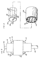
- a typical winding cycle is illustrated for winding a single tooth on a stator 108 having skewed slots.
- the paths labeled A and C illustrate the reciprocating movement of the spindle as it inserts wire radially outwardly from the spindle 18 through the slots of the stator.
- the second servo motor 64 simultaneously drives the spindle 18 in rotational movement whereby a wire exit, defined by a radial passage extending from the longitudinal passage in the spindle 18, follows a path corresponding to the angle of the slot in the stator 108.
- the paths labeled B and D illustrate the path followed by a wire exit on the spindle 18 to position wire along the ends of me stator tooth wherein the oscillating movement of the spindle 18 along the paths B and D is controlled by the second servo motor 64.
- the rate at which the wire is fed from the spindle 18 through slots in the stator 108 along the paths A and C may be different than the rate at which it is fed onto the ends of the tooth 114 of the stator 108 along paths B and D, and further may be varied to compensate for accelerations and decelerations of the winding spindle 18 at the transitions between A-B, B-C, C-D and D-A.
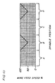
- FIG. 11 an example of the wire speed versus the position of the spindle 18 along the paths A, B, C, D of Fig. 4 is illustrated.
- the wire 30 is fed at a maximum, substantially constant speed as it is fed through the slots in the stator 108.
- the wire speed linearly decreases until the wire exit on the spindle 18 is midway between slots and then increases as it approaches a slot.
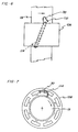
- the layering of a wire 30 is illustrated as the spindle 18 feeds the wire 30 from a wire exit 110 through a slot 112 and around the end of a stator tooth 114.
- a loop of wire will typically be formed as it passes from the wire exit 110 in order to direct the wire radially outwardly and cause it to be positioned at a desired radial position to form a uniform layer of windings 116.
- the spindle shaft 28 may be rotated to a desired position adjacent to another tooth or set of teeth where the next coil is to be wound.
- the programmable controller 22 may be programmed to control the second servo motor 64 for the oscillator tower 60 to position the winding spindle 18 at any particular rotational position desired throughout the winding operation.
- the controller 22 can be programmed to wind any particular configuration for the stator, such that stators having slots arranged at different skew angles may be wound. The necessary changes for altering the winding operation may be easily entered by an operator at the input panel 24, thus eliminating time consuming mechanical adjustments to the machine when an alteration to the winding operation is required.
- a forming operation is performed on the coils at intervals after predetermined numbers of winds of wire are placed on the stator in order to ensure that a compact and properly formed coil is produced.
- the spindle 18 is provided with forming racks 118 which move radially outwardly from the spindle 18 to form the coils 116.
- the racks 118 are actuated for movement by rotation of a top cap 120.
- the top cap 120 includes an upper key 122 (Fig. 8) for engagement by a cap rotator 124 which is supported on the forming tower 16.
- the forming tower 16 includes a rail-like screw driven horizontal positioner 126 actuated by a servo motor 128 controlled by the programmable controller 22.
- vertical positioning of the cap rotator 124 is provided by a further servo motor 130, also controlled by the programmable controller 22, which drives a screw member 132 for positioning the cap rotator 124 along a vertical rail structure 134.
- the cap rotator 124 is actuated in rotating movement by a servo motor 136 which is mounted for movement with the cap actuator 124.
- the programmable controller 22 causes the forming tower 16 to move horizontally and vertically for engaging the cap rotator 124 with the top cap 120.
- the servo motor 136 is actuated to rotate the top cap and thereby actuate the forming racks 118 outwardly.
- a plurality of wires may be provided for winding simultaneously on the stator 108.
- Fig. 8 shows a pair of coils wound simultaneously on opposite sides of the stator 108.
- the wires will be simultaneously fed by the feed mechanism 78 and may be guided through apertures located in the side of the winding spindle 18.
- Fig. 9 illustrates a stator 108 having skewed slots provided with field coil windings 116 wound in accordance with the present invention in combination with a rotor 138 for forming a motor.
- the rotor 138 is formed of a ferrite material and includes alternating north poles 140 and south poles 142 wherein the interfaces 144 between the poles 140, 142 are aligned parallel to a central shaft 146 of the rotor 138. It should be noted that providing one of the stator 108 or rotor 138 with a skewed pole configuration facilitates the elimination of ripple effects in the motor.
- the skewed stator configuration of the present invention simplifies the construction of the motor and significantly reduces the cost of the motor as a result of simplifying the construction and reducing the amount of winding wire required through efficient winding of the field coils on the stator.
Landscapes
- Engineering & Computer Science (AREA)
- Manufacturing & Machinery (AREA)
- Power Engineering (AREA)
- Manufacture Of Motors, Generators (AREA)
Claims (12)
- Verfahren zur Bildung einer Feldspule (116) an einem Stator (108) für eine dynamo-elektrische Maschine, wobei der Stator (108) eine Vielzahl von Schlitzen (112) aufweist, welche durch Statorzähne (41) gebildet werden, das Verfahren beinhaltet:worin Draht (30), welcher durch den Drahtausgang (110) in einer vorbestimmten Rate sowohl während der Rotations-, als auch während der Hin-/Herbewegung von einem Ort oberhalb des Drahtausgang (110) geführt wird, damit der Draht (30) auf den Stator (108) gewickelt werden kann, während sich die Wickelmittel bewegen;Positionierung des Stators (108) in einer Statorwickelmaschine (10), die Wickelmaschine beinhaltet Wickelmittel, welche einen Drahtausgang (110) aufweisen;Zuführung des Drahtes (30) durch den Drahtausgang (110), radial nach außen, zur Platzierung auf dem Stator (108);Bewegung der Wickelmittel, welche rotierend und hin- und herbewegt werden, um den Draht (30) in die Schlitze (112) und um die Enden der Zähne (114) zu leiten; wobei der Draht (30) in eine Feldspule (116) an den Statorzähnen (114) gebildet ist; und
dadurch gekennzeichnet, dass:dieses Verfahren ein Verfahren zur Bildung von Feldspulen (116) auf einem Stator (108) ist, welcher eine Vielzahl von abgeschrägten Schlitzen (112) aufweist, welche durch Statorzähne (114) definiert sind, und unter einem vorbestimmten Anschrägwinkel orientiert sind; unddie Wickelmittel eine Wickelspindel (18) aufweisen, und der Draht (30) mittels Zuführungsmittel (78), durch die Wickelspindel (18) hindurch geführt wird, welche für eine Hin- und Herbewegung mit der Wickelspindel (18) befestigt sind, wobei der Draht (30) in einer geregelten Rate in Relation zu der Wickelspindel (18) angetrieben wird. - Verfahren nach Anspruch 1, worin der Draht (30) den Schlitzen (112) bei einer ersten Geschwindigkeit zugeführt wird, und der Draht (30) den Enden der Zähne (114) in einer zweiten Geschwindigkeit, welche verschieden ist von der ersten Geschwindigkeit, zugeführt wird.
- Verfahren nach Anspruch 1 oder 2, worin der Draht (30) in einer vorbestimmten radialen Lage auf dem Stator (108) zugeführt wird, geregelt durch die Rate, in welcher der Draht (30) durch den Drahtausgang (110) während der Bewegung der Wickelspindel (18) zugeführt wird.
- Verfahren nach Anspruch 1, 2 oder 3, worin der Draht (30) dem Stator (108) zugeführt oder in Lagen auf dem Stator (108) angeordnet wird, worin der Draht (30) in nacheinanderfolgend unterschiedlichen Lagen radial angeordnet wird.
- Verfahren nach Anspruch 4, worin die sukzessiv unterschiedlichen radialen Lagen aufeinanderfolgend radial nach innen gerichtet angeordnet sind.
- Verfahren nach einem der vorangegangenen Ansprüche, welches den Schritt des zur Verfügung stellen eines Formungswerkzeugs (118) beinhaltet, welches sich radial von der Wickelspindel (18) erstreckt; wobei das Formungswerkzeug (118) den Draht (30) radial nach außen hin vorschiebt, wobei er auf die Zähne (114) und in vorbestimmten Intervallen zu vorbestimmten Wicklungszahlen des Drahtes (30) die Zähne (114) umschließend gewickelt wird.
- Verfahren nach einem der vorangegangenen Ansprüche, worin die Wickelspindel (18) in einer Hin- und Herbewegung durch einen ersten Servomotor (48) angetrieben wird und die Wickelspindel (18) in einer Rotationsbewegung durch einen zweiten Servomotor (64) angetrieben wird, und wodurch die Wickelspindel (18) derart angetrieben wird, dass die Rotationsbewegung simultan zu der Hin- und Herbewegung erfolgt, um zu erzielen, dass der Drahtausgang, (110) den angeschrägten Schlitzen (112) folgt.
- Ein Stator (108), hergestellt in Übereinstimmung mit dem Verfahren nach einem der vorangegangenen Ansprüche.
- Eine Vorrichtung (10) zur Bildung einer Feldspule (116) an einem Stator (108) für eine dynamo-elektrische Maschine, wobei die Vorrichtung aufweist:dadurch gekennzeichnet, dass:Mittel (14) zur Unterstützung des Stators (108);Wickelmittel, welche eine sich radial erstreckende Passage (110) zur Führung eines Wickeldrahtes (30) aus diesen Wickelmittel heraus aufweisen, zur Platzierung auf dem Stator (108);Mittel (44) zur Beförderung der sich radial erstreckenden Passage (110) zu unterschiedlichen longitudinalen Positionen, relativ zu diesem Mittel (14), zur Unterstützung des Stators (108);Mittel (60) zur Beförderung der sich radial erstreckenden Passage (110) zu unterschiedlichen, auf einer Kreisbahn befindlichen Positionen relativ zu dem Mittel (14), zur Unterstützung des Stators (108); undZuführungsmittel (78) zum Vorschub eines Wickeldrahtes (30) in das Wickelmittel und aus dem Wickelmittel, durch die sich radial erstreckende Passage (110) in einer vorbestimmten Rate;Mittel (22) zum Ändern der vorgegebenen Rate zur Verfügung gestellt werden, zu welcher der Draht (30) mittels Zuführungsmittel (78) vorgeschoben wird, worin die Mittel (22) zu Veränderungen der vorgegebene Rate in dem Maße variieren, in welchem der Draht (30) in Bezug auf die longitudinalen und auf Kreisbahnen befindlichen Positionen der sich radial erstreckenden Passage (110) relativ zu dem Mittel (14) zur Unterstützung des Stators (108) zugeführt wird;die Wickelmittel, welche eine längliche zylindrische Wickelspindel (18) enthalten, welche sich durch die Mittel (14) zur Unterstützung des Stators (108) ausdehnen und eine sich longitudinal ausgedehnte interne Passage zur Aufnahme eines Wickeldrahtes (30)aufweisen; undZuführungsmittel (78), welche einsetzbar sind, um den Draht (30) in die sich longitudinal ausgedehnte Passage und aus der Wickelspindel (18) durch die sich radial erstreckende Passage (110) führen, die Zuführungsmittel (78) sind befestigt zur Hin- und Herbewegung mit der Wickelspindel (18), wobei der Draht in einer geregelten Rate in Bezug auf die Wickelspindel angetrieben wird.
- Vorrichtung nach Anspruch 9, wobei die Zuführungsmittel (78) einen Drahtzuführungsservomotor (96) aufweisen.
- Vorrichtung nach Anspruch 10, wobei die Mittel (22) zur Veränderung der vorgegebenen Rate einen programmierbaren Controller enthalten, welcher mit dem Drahtzuführungsservomotor (96) zur Kontrolle der Geschwindigkeit des Drahtzuführungsservomotors (96) verbunden ist.
- Vorrichtung nach Anspruch 10 oder 11, wobei die Mittel (44, 60), welche zur Bewegung entlang der radial ausgedehnten Passage (110) zu unterschiedlichen longitudinalen oder sich auf Kreisbahnen befindlichen Positionen vorgesehen ist, jeweils longitudinale oder sich auf Kreisbahnen befindlich positionierte Servomotoren (48, 64) aufweisen, welche bedienbar zu den programmierbaren Controller (22) verbunden sind, derart, dass sie die Geschwindigkeit des Drahtzuführungsservomotors (96) in Bezug auf die Positionen der longitudinalen oder sich auf Kreisbahnen befindlich positionierten Servomotoren (48, 64) regeln.
Applications Claiming Priority (5)
| Application Number | Priority Date | Filing Date | Title |
|---|---|---|---|
| US2629396P | 1996-09-10 | 1996-09-10 | |
| US26293P | 1996-09-10 | ||
| US4493197P | 1997-04-25 | 1997-04-25 | |
| US44931P | 1997-04-25 | ||
| PCT/US1997/015969 WO1998011653A1 (en) | 1996-09-10 | 1997-09-09 | Method and apparatus for winding and forming field windings for dynamo-electric machines |
Publications (3)
| Publication Number | Publication Date |
|---|---|
| EP0925633A1 EP0925633A1 (de) | 1999-06-30 |
| EP0925633A4 EP0925633A4 (de) | 2002-03-20 |
| EP0925633B1 true EP0925633B1 (de) | 2004-11-24 |
Family
ID=26701054
Family Applications (1)
| Application Number | Title | Priority Date | Filing Date |
|---|---|---|---|
| EP97942411A Expired - Lifetime EP0925633B1 (de) | 1996-09-10 | 1997-09-09 | Verfahren und vorrichtung zum wickeln und formen von wicklungen elektrischer maschinen |
Country Status (8)
| Country | Link |
|---|---|
| US (1) | US5964429A (de) |
| EP (1) | EP0925633B1 (de) |
| JP (1) | JP3925739B2 (de) |
| CN (1) | CN1238947C (de) |
| CA (1) | CA2265556C (de) |
| DE (1) | DE69731754T2 (de) |
| PT (1) | PT925633E (de) |
| WO (1) | WO1998011653A1 (de) |
Cited By (1)
| Publication number | Priority date | Publication date | Assignee | Title |
|---|---|---|---|---|
| WO2023198831A1 (en) * | 2022-04-13 | 2023-10-19 | Atop S.P.A. | Assembly for tensioning wires for forming components of electrical windings |
Families Citing this family (24)
| Publication number | Priority date | Publication date | Assignee | Title |
|---|---|---|---|---|
| JP3451033B2 (ja) * | 1999-04-28 | 2003-09-29 | 日特エンジニアリング株式会社 | 巻線装置 |
| US6533208B1 (en) * | 1999-08-12 | 2003-03-18 | Axis U.S.A., Inc. | Winding cores with stratification motion |
| JP2001251817A (ja) * | 2000-03-07 | 2001-09-14 | Moric Co Ltd | 永久磁石界磁モータの組立て装置 |
| EP1281232A1 (de) | 2000-04-13 | 2003-02-05 | Globe Products Inc. | Statorwicklungs- und spulenanschlussabschlussverfahren und -vorrichtung |
| JP3926741B2 (ja) * | 2000-10-16 | 2007-06-06 | グロウブ モーターズ,インコーポレイテッド | ダイナモ電気ステーターの巻付け装置 |
| EP1276207A3 (de) * | 2001-07-11 | 2004-12-22 | Kabushiki Kaisha Moric | Anker für rotierende elektrische Maschine |
| JP2003032935A (ja) * | 2001-07-11 | 2003-01-31 | Moric Co Ltd | 回転界磁型電気機器の電機子 |
| EP1282217A3 (de) * | 2001-08-03 | 2004-08-04 | Kabushiki Kaisha Moric | Verfahren zur Wicklung eines geschrägten Ankers |
| US6851175B2 (en) * | 2001-09-12 | 2005-02-08 | Delphi Technologies, Inc. | Wound stator core and method of making |
| CA2452197A1 (en) * | 2002-12-09 | 2004-06-09 | Axis Usa, Inc. | Multiple wire winding |
| US7028942B2 (en) * | 2003-09-23 | 2006-04-18 | Globe Motors, Inc. | Horizontal winding machine |
| US7325764B2 (en) * | 2004-04-26 | 2008-02-05 | Globe Motors, Inc. | Method and apparatus for winding field coils for dynamo-electric machines |
| US7419116B2 (en) * | 2004-04-26 | 2008-09-02 | Globe Motors, Inc. | Method and apparatus for winding field coils for dynamo-electric machines |
| JP3913242B2 (ja) * | 2004-09-13 | 2007-05-09 | 日特エンジニアリング株式会社 | 多極電機子の巻線方法及び巻線装置 |
| US20080016676A1 (en) * | 2006-07-18 | 2008-01-24 | Jones Robert M | Automatic winder for an inside brushless stator |
| US8028396B2 (en) * | 2006-07-18 | 2011-10-04 | Robert M. Jones | Automatic wire winding of inside brushless stator |
| US7981465B2 (en) * | 2007-01-16 | 2011-07-19 | Globe Motors, Inc. | Method and apparatus for powder coating stator stacks |
| DE102008040346A1 (de) * | 2008-07-11 | 2010-01-14 | Robert Bosch Gmbh | Hubverstellvorrichtung sowie Vorrichtung zum Aufbringen eines Wickeldrahtes auf ein zu bewickelndes Bauteil |
| TW201138270A (en) * | 2010-04-30 | 2011-11-01 | Sheng-Jun Cai | Manufacturing method of a skew stator module |
| WO2014153558A1 (en) | 2013-03-22 | 2014-09-25 | Eaton Corporation | Cam hard stop for end of life |
| US9771985B2 (en) | 2014-03-14 | 2017-09-26 | Eaton Corporation | Bracket barb pressure plate stop |
| CN104993663B (zh) * | 2015-07-28 | 2017-07-28 | 东莞市福特机械有限公司 | 一种新型自动绕线机 |
| DE102016014371A1 (de) * | 2016-12-02 | 2018-06-07 | Audi Ag | Nadelwickelvorrichtung |
| DE102020116383A1 (de) * | 2020-06-22 | 2021-12-23 | Valeo Siemens Eautomotive Germany Gmbh | Verfahren zur Herstellung eines geschrägten Stators |
Family Cites Families (44)
| Publication number | Priority date | Publication date | Assignee | Title |
|---|---|---|---|---|
| US2632602A (en) * | 1950-03-11 | 1953-03-24 | Redmond Company Inc | Electrical coil winding |
| US2952069A (en) * | 1957-01-23 | 1960-09-13 | Sperry Rand Corp | Method of winding stators |
| US2998937A (en) * | 1957-10-15 | 1961-09-05 | Sperry Rand Corp | Winding apparatus for dynamo electric machines |
| US3081043A (en) * | 1957-12-02 | 1963-03-12 | Wayne J Morrill | Winding machine |
| US3061211A (en) * | 1958-07-03 | 1962-10-30 | Bendix Corp | Apparatus for winding field coils |
| US3334825A (en) * | 1964-01-27 | 1967-08-08 | Lincoln Tool And Mfg Co | Stator coil winding machine |
| US3338526A (en) * | 1964-07-27 | 1967-08-29 | Possis Machine Corp | Stator winder |
| US3323734A (en) * | 1965-04-02 | 1967-06-06 | Gorski Henry J | Stator core winding machine |
| US3493186A (en) * | 1965-12-08 | 1970-02-03 | Robert E Arick | Process and apparatus for winding coils |
| US3524600A (en) * | 1967-10-18 | 1970-08-18 | Lincoln Tool & Mfg Co | Stator winding machine |
| US3539121A (en) * | 1968-01-25 | 1970-11-10 | Lincoln Tool & Mfg Co | Machine for winding stators with skewed slots |
| US3629925A (en) * | 1969-12-04 | 1971-12-28 | Essex International Inc | Apparatus for compacting dynamoelectric machine coils with means for preventing lamination distortion |
| US3753282A (en) * | 1971-03-15 | 1973-08-21 | Siemens Ag | Member for use in the shaping of coil ends of stator windings disposed in sheet metal stator assemblies of electrical machines |
| US3903593A (en) * | 1971-10-15 | 1975-09-09 | Gen Electric | Method for handling magnetic cores and performing winding treatment procedures |
| US3716199A (en) * | 1971-12-01 | 1973-02-13 | Westinghouse Electric Corp | Stator winding machine |
| US3822830A (en) * | 1972-03-30 | 1974-07-09 | R Peters | Stator core winding machine |
| US3903933A (en) * | 1973-02-12 | 1975-09-09 | Essex International Inc | Apparatus and method for forming dynamoelectric machine field windings by pushing |
| US3995785A (en) * | 1973-02-12 | 1976-12-07 | Essex International, Inc. | Apparatus and method for forming dynamoelectric machine field windings by pushing |
| US3841133A (en) * | 1973-08-13 | 1974-10-15 | Westinghouse Electric Corp | Apparatus and method for shaping end turns of coils in dynamo-electric machine cores |
| US3856221A (en) * | 1973-09-04 | 1974-12-24 | Essex International Inc | Push-pull stator winding apparatus and method |
| US3857221A (en) * | 1973-11-27 | 1974-12-31 | A Schmermund | Folding device for packaging material |
| US3913373A (en) * | 1974-01-14 | 1975-10-21 | Gen Electric | Method and apparatus for forming winding end turns |
| US3985164A (en) * | 1974-05-28 | 1976-10-12 | Essex International, Inc. | Apparatus and method for forming circular dynamoelectric machine field windings by pushing |
| CA1021543A (en) * | 1974-05-28 | 1977-11-29 | Patrick L. Grawcock | Apparatus and method for forming circular dynamoelectric machine field windings by pushing |
| US4051595A (en) * | 1975-07-07 | 1977-10-04 | General Electric Company | Methods for setting insulators and pressing end turns |
| US4033385A (en) * | 1976-09-02 | 1977-07-05 | Essex Group, Inc. | Apparatus and method for forming dynamoelectric machine field windings by pushing |
| US4053111A (en) * | 1976-12-06 | 1977-10-11 | Windamatic Systems, Inc. | Apparatus and method for producing distributed stator windings |
| US4106189A (en) * | 1977-02-28 | 1978-08-15 | Peters Robert W | Stator coil press |
| US4290190A (en) * | 1980-02-25 | 1981-09-22 | Advanced Machine And Tool Corporation | Method and apparatus for spreading stator windings |
| US4498636A (en) * | 1982-02-25 | 1985-02-12 | Kollmorgen Technologies Corporation | Stator winding apparatus and method |
| US4588143A (en) * | 1982-10-22 | 1986-05-13 | K & S Schrittmotoren Gmbh | Stator winding machine |
| US4724604A (en) * | 1985-05-09 | 1988-02-16 | Matsushita Electric Industrial Co., Ltd. | Method of manufacturing a part with a coil |
| US4880173A (en) * | 1987-06-09 | 1989-11-14 | Globe Products Inc. | Wire supply method and apparatus |
| IT1219093B (it) * | 1988-03-10 | 1990-04-24 | Axis Spa | Macchina avvolgitrice di statori bipolari |
| JP2523933B2 (ja) * | 1990-04-26 | 1996-08-14 | 三菱電機株式会社 | ステ―タの製造方法 |
| JPH04229053A (ja) * | 1990-08-27 | 1992-08-18 | Nippondenso Co Ltd | 界磁コイル製造装置 |
| US5056212A (en) * | 1990-09-20 | 1991-10-15 | Advanced Machine & Tool Corporation | Apparatus for preforming and final forming of stator coil end turns |
| US5134769A (en) * | 1990-09-20 | 1992-08-04 | Advanced Machine And Tool Corporation | Method and apparatus for preforming and final forming of stator coil end turns |
| US5186405A (en) * | 1990-09-27 | 1993-02-16 | Globe Products Inc. | Programmable lead pull method and apparatus for use with a stator winding machine |
| US5370324A (en) * | 1990-09-25 | 1994-12-06 | Globe Products Inc. | Stator winding method and apparatus |
| JP3048252B2 (ja) * | 1991-03-15 | 2000-06-05 | 株式会社小田原エンジニアリング | ステータ巻線機 |
| US5235738A (en) * | 1991-06-17 | 1993-08-17 | Pease Windamatic Systems, Inc. | Apparatus for end turn shaping |
| CA2092264A1 (en) * | 1992-04-15 | 1993-10-16 | Massimo Ponzio | Stator winding methods and apparatus |
| US5732900A (en) * | 1995-10-30 | 1998-03-31 | Electrowind, Inc. | Tool including a winding spindle for winding and forming dynamoelectric machine field windings |
-
1997
- 1997-09-09 CN CNB971977836A patent/CN1238947C/zh not_active Expired - Fee Related
- 1997-09-09 EP EP97942411A patent/EP0925633B1/de not_active Expired - Lifetime
- 1997-09-09 DE DE69731754T patent/DE69731754T2/de not_active Expired - Lifetime
- 1997-09-09 JP JP51379798A patent/JP3925739B2/ja not_active Expired - Fee Related
- 1997-09-09 WO PCT/US1997/015969 patent/WO1998011653A1/en not_active Ceased
- 1997-09-09 CA CA002265556A patent/CA2265556C/en not_active Expired - Lifetime
- 1997-09-09 PT PT97942411T patent/PT925633E/pt unknown
- 1997-09-10 US US08/926,902 patent/US5964429A/en not_active Expired - Lifetime
Cited By (1)
| Publication number | Priority date | Publication date | Assignee | Title |
|---|---|---|---|---|
| WO2023198831A1 (en) * | 2022-04-13 | 2023-10-19 | Atop S.P.A. | Assembly for tensioning wires for forming components of electrical windings |
Also Published As
| Publication number | Publication date |
|---|---|
| JP3925739B2 (ja) | 2007-06-06 |
| DE69731754T2 (de) | 2005-12-01 |
| CN1276099A (zh) | 2000-12-06 |
| EP0925633A1 (de) | 1999-06-30 |
| CA2265556C (en) | 2004-11-02 |
| PT925633E (pt) | 2005-01-31 |
| WO1998011653A1 (en) | 1998-03-19 |
| CA2265556A1 (en) | 1998-03-19 |
| EP0925633A4 (de) | 2002-03-20 |
| JP2001521719A (ja) | 2001-11-06 |
| CN1238947C (zh) | 2006-01-25 |
| DE69731754D1 (de) | 2004-12-30 |
| US5964429A (en) | 1999-10-12 |
Similar Documents
| Publication | Publication Date | Title |
|---|---|---|
| EP0925633B1 (de) | Verfahren und vorrichtung zum wickeln und formen von wicklungen elektrischer maschinen | |
| JP3669966B2 (ja) | 巻線方法及び巻線装置 | |
| KR100454374B1 (ko) | 코일 권선기 및 와이어 권선 방법 | |
| US5499775A (en) | Winding machine with programmable traverse control | |
| EP0538905B1 (de) | Betätigungsgerät für Legenadeln zur Herstellung von Feldwicklungen elektrischer Motoren | |
| EP0200236B1 (de) | Maschine und Verfahren zur Formung von Spulen auf elektrische Motorstatoren | |
| EP1076401B1 (de) | Wicklung von Kernen mit Stratifikationsbewegung | |
| EP0180359B1 (de) | Verfahren und Vorrichtung zur Bildung von Motorspulen mit zwei Schichten | |
| US3977444A (en) | Apparatus and method for developing wound coils for electromagnetic devices and for interdependently conditioning winding apparatus and coil placing apparatus | |
| WO2002033809A1 (en) | Machine for winding dynamo-electric stators | |
| JP2682587B2 (ja) | 巻線形成方法および巻線形成装置 | |
| EP0526819B1 (de) | Programmierbar gesteuerte Wickelverfahren für Unterteile elektrischer Motoren und Vorrichtung | |
| EP1435685B1 (de) | Apparat und Verfahren zur Herstellung einer Mehrleiter-Wicklung | |
| JP4040784B2 (ja) | 巻線装置 | |
| US4771958A (en) | Apparatus and method for simultaneously winding two strands of wire on a bobbin | |
| US3958611A (en) | Apparatus for winding wire coils for electrical machines | |
| JP4084083B2 (ja) | ステータコアの巻線方法及びその装置 | |
| MXPA99002284A (en) | Method and apparatus for winding and forming field windings for dynamo-electric machines | |
| US5895004A (en) | Coil winding apparatus for large diameter magnetic rings | |
| KR0172295B1 (ko) | 새들형 편향 코일의 권선방법 및 권선장치 | |
| JP2003333809A5 (de) | ||
| JPH08225244A (ja) | コイル巻線方法並びに装置 | |
| JPH0438507Y2 (de) | ||
| EP3975398A1 (de) | Nadelwickelmaschine | |
| US20050005423A1 (en) | Methods for dynamo-electric machine insulation handling |
Legal Events
| Date | Code | Title | Description |
|---|---|---|---|
| PUAI | Public reference made under article 153(3) epc to a published international application that has entered the european phase |
Free format text: ORIGINAL CODE: 0009012 |
|
| 17P | Request for examination filed |
Effective date: 19990401 |
|
| AK | Designated contracting states |
Kind code of ref document: A1 Designated state(s): CH DE ES FR GB IE IT LI PT |
|
| A4 | Supplementary search report drawn up and despatched |
Effective date: 20020204 |
|
| AK | Designated contracting states |
Kind code of ref document: A4 Designated state(s): CH DE ES FR GB IE IT LI PT |
|
| RIC1 | Information provided on ipc code assigned before grant |
Free format text: 7H 02K 15/02 A, 7H 02K 15/085 B |
|
| RAP1 | Party data changed (applicant data changed or rights of an application transferred) |
Owner name: GLOBE MOTORS, INC. |
|
| 17Q | First examination report despatched |
Effective date: 20030731 |
|
| GRAP | Despatch of communication of intention to grant a patent |
Free format text: ORIGINAL CODE: EPIDOSNIGR1 |
|
| GRAS | Grant fee paid |
Free format text: ORIGINAL CODE: EPIDOSNIGR3 |
|
| GRAA | (expected) grant |
Free format text: ORIGINAL CODE: 0009210 |
|
| AK | Designated contracting states |
Kind code of ref document: B1 Designated state(s): CH DE ES FR GB IE IT LI PT |
|
| PG25 | Lapsed in a contracting state [announced via postgrant information from national office to epo] |
Ref country code: LI Free format text: LAPSE BECAUSE OF FAILURE TO SUBMIT A TRANSLATION OF THE DESCRIPTION OR TO PAY THE FEE WITHIN THE PRESCRIBED TIME-LIMIT Effective date: 20041124 Ref country code: CH Free format text: LAPSE BECAUSE OF FAILURE TO SUBMIT A TRANSLATION OF THE DESCRIPTION OR TO PAY THE FEE WITHIN THE PRESCRIBED TIME-LIMIT Effective date: 20041124 |
|
| REG | Reference to a national code |
Ref country code: GB Ref legal event code: FG4D |
|
| REG | Reference to a national code |
Ref country code: CH Ref legal event code: EP |
|
| REF | Corresponds to: |
Ref document number: 69731754 Country of ref document: DE Date of ref document: 20041230 Kind code of ref document: P |
|
| REG | Reference to a national code |
Ref country code: IE Ref legal event code: FG4D |
|
| REG | Reference to a national code |
Ref country code: PT Ref legal event code: SC4A Effective date: 20041203 |
|
| PG25 | Lapsed in a contracting state [announced via postgrant information from national office to epo] |
Ref country code: ES Free format text: LAPSE BECAUSE OF FAILURE TO SUBMIT A TRANSLATION OF THE DESCRIPTION OR TO PAY THE FEE WITHIN THE PRESCRIBED TIME-LIMIT Effective date: 20050306 |
|
| REG | Reference to a national code |
Ref country code: CH Ref legal event code: PL |
|
| PG25 | Lapsed in a contracting state [announced via postgrant information from national office to epo] |
Ref country code: IE Free format text: LAPSE BECAUSE OF NON-PAYMENT OF DUE FEES Effective date: 20050909 |
|
| PLBE | No opposition filed within time limit |
Free format text: ORIGINAL CODE: 0009261 |
|
| STAA | Information on the status of an ep patent application or granted ep patent |
Free format text: STATUS: NO OPPOSITION FILED WITHIN TIME LIMIT |
|
| 26N | No opposition filed |
Effective date: 20050825 |
|
| ET | Fr: translation filed | ||
| REG | Reference to a national code |
Ref country code: IE Ref legal event code: MM4A |
|
| REG | Reference to a national code |
Ref country code: FR Ref legal event code: PLFP Year of fee payment: 19 |
|
| REG | Reference to a national code |
Ref country code: FR Ref legal event code: PLFP Year of fee payment: 20 |
|
| PGFP | Annual fee paid to national office [announced via postgrant information from national office to epo] |
Ref country code: DE Payment date: 20160921 Year of fee payment: 20 Ref country code: GB Payment date: 20160920 Year of fee payment: 20 |
|
| PGFP | Annual fee paid to national office [announced via postgrant information from national office to epo] |
Ref country code: PT Payment date: 20160907 Year of fee payment: 20 Ref country code: FR Payment date: 20160921 Year of fee payment: 20 |
|
| PGFP | Annual fee paid to national office [announced via postgrant information from national office to epo] |
Ref country code: IT Payment date: 20160922 Year of fee payment: 20 |
|
| REG | Reference to a national code |
Ref country code: DE Ref legal event code: R071 Ref document number: 69731754 Country of ref document: DE |
|
| REG | Reference to a national code |
Ref country code: GB Ref legal event code: PE20 Expiry date: 20170908 |
|
| PG25 | Lapsed in a contracting state [announced via postgrant information from national office to epo] |
Ref country code: GB Free format text: LAPSE BECAUSE OF EXPIRATION OF PROTECTION Effective date: 20170908 Ref country code: PT Free format text: LAPSE BECAUSE OF EXPIRATION OF PROTECTION Effective date: 20170919 |