EP0925708B1 - Procede et dispositif pour augmenter la portee de la voie de transmission entre des unites fonctionnelles du poste d'abonne rnis avec une bande passante minimisee - Google Patents
Procede et dispositif pour augmenter la portee de la voie de transmission entre des unites fonctionnelles du poste d'abonne rnis avec une bande passante minimisee Download PDFInfo
- Publication number
- EP0925708B1 EP0925708B1 EP97944704A EP97944704A EP0925708B1 EP 0925708 B1 EP0925708 B1 EP 0925708B1 EP 97944704 A EP97944704 A EP 97944704A EP 97944704 A EP97944704 A EP 97944704A EP 0925708 B1 EP0925708 B1 EP 0925708B1
- Authority
- EP
- European Patent Office
- Prior art keywords
- channel
- data
- isdn
- transmission
- interface
- Prior art date
- Legal status (The legal status is an assumption and is not a legal conclusion. Google has not performed a legal analysis and makes no representation as to the accuracy of the status listed.)
- Expired - Lifetime
Links
- 230000005540 biological transmission Effects 0.000 title claims abstract description 117
- 238000000034 method Methods 0.000 title claims abstract description 22
- 230000008569 process Effects 0.000 title abstract description 4
- 238000006243 chemical reaction Methods 0.000 claims description 36
- 238000007906 compression Methods 0.000 claims description 21
- 230000006835 compression Effects 0.000 claims description 21
- 230000006870 function Effects 0.000 claims description 8
- 238000004891 communication Methods 0.000 claims description 6
- 230000003936 working memory Effects 0.000 claims description 5
- 230000006837 decompression Effects 0.000 claims description 4
- 125000000524 functional group Chemical group 0.000 claims 2
- 230000003139 buffering effect Effects 0.000 claims 1
- XZWYZXLIPXDOLR-UHFFFAOYSA-N metformin Chemical compound CN(C)C(=N)NC(N)=N XZWYZXLIPXDOLR-UHFFFAOYSA-N 0.000 claims 1
- 230000015654 memory Effects 0.000 abstract description 2
- 238000011084 recovery Methods 0.000 abstract description 2
- 230000002123 temporal effect Effects 0.000 abstract 1
- 229940049705 immune stimulating antibody conjugate Drugs 0.000 description 25
- 230000011664 signaling Effects 0.000 description 7
- 230000001360 synchronised effect Effects 0.000 description 7
- 102100040079 A-kinase anchor protein 4 Human genes 0.000 description 2
- 101710109924 A-kinase anchor protein 4 Proteins 0.000 description 2
- 101000906396 Mus musculus Glutathione S-transferase Mu 5 Proteins 0.000 description 2
- 238000013144 data compression Methods 0.000 description 2
- 238000010586 diagram Methods 0.000 description 2
- 230000001771 impaired effect Effects 0.000 description 2
- 230000004913 activation Effects 0.000 description 1
- 230000015572 biosynthetic process Effects 0.000 description 1
- 230000008859 change Effects 0.000 description 1
- 230000009849 deactivation Effects 0.000 description 1
Images



Classifications
-
- H—ELECTRICITY
- H04—ELECTRIC COMMUNICATION TECHNIQUE
- H04Q—SELECTING
- H04Q11/00—Selecting arrangements for multiplex systems
- H04Q11/04—Selecting arrangements for multiplex systems for time-division multiplexing
- H04Q11/0428—Integrated services digital network, i.e. systems for transmission of different types of digitised signals, e.g. speech, data, telecentral, television signals
- H04Q11/0435—Details
- H04Q11/0471—Terminal access circuits
-
- H—ELECTRICITY
- H04—ELECTRIC COMMUNICATION TECHNIQUE
- H04Q—SELECTING
- H04Q11/00—Selecting arrangements for multiplex systems
- H04Q11/04—Selecting arrangements for multiplex systems for time-division multiplexing
- H04Q11/0428—Integrated services digital network, i.e. systems for transmission of different types of digitised signals, e.g. speech, data, telecentral, television signals
-
- H—ELECTRICITY
- H04—ELECTRIC COMMUNICATION TECHNIQUE
- H04Q—SELECTING
- H04Q2213/00—Indexing scheme relating to selecting arrangements in general and for multiplex systems
- H04Q2213/13034—A/D conversion, code compression/expansion
-
- H—ELECTRICITY
- H04—ELECTRIC COMMUNICATION TECHNIQUE
- H04Q—SELECTING
- H04Q2213/00—Indexing scheme relating to selecting arrangements in general and for multiplex systems
- H04Q2213/13093—Personal computer, PC
-
- H—ELECTRICITY
- H04—ELECTRIC COMMUNICATION TECHNIQUE
- H04Q—SELECTING
- H04Q2213/00—Indexing scheme relating to selecting arrangements in general and for multiplex systems
- H04Q2213/13094—Range extender
-
- H—ELECTRICITY
- H04—ELECTRIC COMMUNICATION TECHNIQUE
- H04Q—SELECTING
- H04Q2213/00—Indexing scheme relating to selecting arrangements in general and for multiplex systems
- H04Q2213/13174—Data transmission, file transfer
-
- H—ELECTRICITY
- H04—ELECTRIC COMMUNICATION TECHNIQUE
- H04Q—SELECTING
- H04Q2213/00—Indexing scheme relating to selecting arrangements in general and for multiplex systems
- H04Q2213/13201—Change-over of service during connection
-
- H—ELECTRICITY
- H04—ELECTRIC COMMUNICATION TECHNIQUE
- H04Q—SELECTING
- H04Q2213/00—Indexing scheme relating to selecting arrangements in general and for multiplex systems
- H04Q2213/13202—Network termination [NT]
-
- H—ELECTRICITY
- H04—ELECTRIC COMMUNICATION TECHNIQUE
- H04Q—SELECTING
- H04Q2213/00—Indexing scheme relating to selecting arrangements in general and for multiplex systems
- H04Q2213/13204—Protocols
-
- H—ELECTRICITY
- H04—ELECTRIC COMMUNICATION TECHNIQUE
- H04Q—SELECTING
- H04Q2213/00—Indexing scheme relating to selecting arrangements in general and for multiplex systems
- H04Q2213/13209—ISDN
-
- H—ELECTRICITY
- H04—ELECTRIC COMMUNICATION TECHNIQUE
- H04Q—SELECTING
- H04Q2213/00—Indexing scheme relating to selecting arrangements in general and for multiplex systems
- H04Q2213/13214—Clock signals
-
- H—ELECTRICITY
- H04—ELECTRIC COMMUNICATION TECHNIQUE
- H04Q—SELECTING
- H04Q2213/00—Indexing scheme relating to selecting arrangements in general and for multiplex systems
- H04Q2213/13292—Time division multiplexing, TDM
-
- H—ELECTRICITY
- H04—ELECTRIC COMMUNICATION TECHNIQUE
- H04Q—SELECTING
- H04Q2213/00—Indexing scheme relating to selecting arrangements in general and for multiplex systems
- H04Q2213/13293—TASI, irregular time division, burst switching
-
- H—ELECTRICITY
- H04—ELECTRIC COMMUNICATION TECHNIQUE
- H04Q—SELECTING
- H04Q2213/00—Indexing scheme relating to selecting arrangements in general and for multiplex systems
- H04Q2213/13298—Local loop systems, access network
-
- H—ELECTRICITY
- H04—ELECTRIC COMMUNICATION TECHNIQUE
- H04Q—SELECTING
- H04Q2213/00—Indexing scheme relating to selecting arrangements in general and for multiplex systems
- H04Q2213/13333—Earth satellites
-
- H—ELECTRICITY
- H04—ELECTRIC COMMUNICATION TECHNIQUE
- H04Q—SELECTING
- H04Q2213/00—Indexing scheme relating to selecting arrangements in general and for multiplex systems
- H04Q2213/1336—Synchronisation
-
- H—ELECTRICITY
- H04—ELECTRIC COMMUNICATION TECHNIQUE
- H04Q—SELECTING
- H04Q2213/00—Indexing scheme relating to selecting arrangements in general and for multiplex systems
- H04Q2213/13383—Hierarchy of switches, main and subexchange, e.g. satellite exchange
-
- H—ELECTRICITY
- H04—ELECTRIC COMMUNICATION TECHNIQUE
- H04Q—SELECTING
- H04Q2213/00—Indexing scheme relating to selecting arrangements in general and for multiplex systems
- H04Q2213/13389—LAN, internet
-
- H—ELECTRICITY
- H04—ELECTRIC COMMUNICATION TECHNIQUE
- H04Q—SELECTING
- H04Q2213/00—Indexing scheme relating to selecting arrangements in general and for multiplex systems
- H04Q2213/13392—Channels assigned according to rules
-
- H—ELECTRICITY
- H04—ELECTRIC COMMUNICATION TECHNIQUE
- H04Q—SELECTING
- H04Q2213/00—Indexing scheme relating to selecting arrangements in general and for multiplex systems
- H04Q2213/13395—Permanent channel, leased line
Definitions
- the invention relates to a method and a device for increasing the range the transmission path between functional units of the ISDN subscriber line based on an ISDN interface, such as that used by CCITT 1.400 - ISDN users Network Interface and 1.430 - Basic User Network Interface is standardized.
- an ISDN interface such as that used by CCITT 1.400 - ISDN users Network Interface and 1.430 - Basic User Network Interface is standardized.
- the ISDN Integrated Services Digital Network
- TE ISDN terminals
- NT Network terminations
- LAPM frame A connection access protocol is used for data communication (LAPM frame), which uses the signal delay and noise in the satellite channel should bridge.
- LAPD frame Protocol 1
- Protocol 2 Protocol 2
- Transmission medium transmit information in a bandwidth of 160 kbit / s and thus considerable and expensive bandwidth for data transmission z.
- When transmitting data, in particular via satellite channels there is a considerable need for shortened bandwidths or for precisely defined bandwidths in a size of, for example, 64 or 128 kbit / s.
- a number of satellite service providers operate terminals with 64 kbit / s channels.
- the compression or decompression of the B-channel data after method step b) is preferably such that the same characters with a Repetition counter and an identifier and during decompression marked repetitions of characters are resolved again.
- the naturally occurring fluctuations in the required size of the data rate for the Transmission of the B, D channel information and the compression information balanced in the data transmission in that the terminal or network side transmitted binary coded data by means of an organized according to the FIFO principle Storage device of appropriate depth can be buffered.
- the method can advantageously up to the bandwidth required for data transmission be reduced to the net data rate of the B channels to be transmitted.
- the character repetitions occurring in the B1 and B2 channel data stream are used for the compression. If such character repetitions are recognized, a correspondingly labeled compression block is formed for the respective channel, in which it is indicated how much identical data was found in the output stream. A compression block is formed even if the data stream is not reduced as a result. This block ensures the synchronization to byte limit for the B-channel data stream.
- B-channel sections with a fixed length are advantageously formed and transmitted, the minimum length of the D-channel blocks and B-channel compression blocks being 1/4 of the B-channel sections and the D-channel blocks being a multiple of that May have minimum length.
- the transmission interrupted the B-channel sections and instead of the B-channel sections these blocks the Transmission means for transmission to the receiver side supplied, the Transmission of the D-channel blocks is preferably carried out.
- the transmission of the B channel sections is advantageous interrupted at a point divisible by 4.
- the B channel sections formed become the receiver side with a from the ISDN network clock derived clock by means of known transmission equipment via satellite or other transmission channels transmitted.
- This bit clock is used on the terminal side for the ISDN interface from the bit transmission clock using a PLL circuit (phase locked loop) recovered.
- the received data bits are analyzed on the receiver side, recognized D-channel blocks resolved and the D-channel data fed directly to the code converter.
- recognized B-channel data the B-channel compression blocks are resolved, according to B1 and B2 channel data buffered in the storage device and in accordance with the recovered clock fed to the code converter and the binary-coded data in ISDN-specific encoded data converted.
- Both the terminal and network-side conversion of the ISDN-specific encoded data into binary encoded data is carried out according to known principles by means of a code converter, preferably an ISDN Subscriber Access Controller.
- the method according to the invention can advantageously also be carried out in such a way that in the times in which the ISDN interface is not active, the transmission of digital, serial data without Code conversion takes place via the transmission medium. This is particularly possible if several channels are provided by the transmission means.
- the clock 512 kHz from the ISAC circuit of the ISDN interface is in the processor in Microcomputer (6) controlled module for clock generation (3) used to correspond to a additional switch position in the mode switch (5) for the respective interface modules (2) to generate the transfer clock.
- the microcomputer (6) forms D-channel blocks from the available D-channel data and transfers them it prefers the addressed SIO instead of the B-channel sections, with the relative Address in the B-channel section is also transmitted.
- the addressed SIO receives bit serial in the interface module (2) Data via the interface in the interface module (2). If the first data part in the SIO Corresponding signaling bits are received in a register of the SIO set. The processor of the microcomputer (6) polls this register cyclically and analyzes it the received data. B channel data is separated into B1 and B2 channel data in RAM of the microcomputer (6) temporarily stored. Detected D channel blocks are resolved and the D-channel register of the ISAC circuit in the interface module (1). Detected B-channel compression blocks are resolved and in the RAM of the microcomputer (6) cached and to the ISAC circuit in the interface module (1) forwarded.
- Microcomputer (6), ISAC circuit in the interface module (1) and SIO in Interface module (2) work together in the same way as in the master device Forwarding of the B and D channel data between the ISDN interface and the X channel.
- the device according to FIG. 1 operates in master mode as follows:
- the PEB 2086 signals by means of a register that it has to take over a new B1 and B2 channel bytes and at the same time a complete B1 and B2 channel byte for transfer is ready by the processor.
- the processor of the microcomputer (6) asks Signaling register of the PEB 2086 cyclically and takes over the finished B-channel bytes in its working memory or transfers the B-channel bytes.
- the B-channel sections are sent and sent in a suitable depth FIFO queue on the receiving side in order to compensate for the increased need for transmission rate caused by the appearance of D-channel blocks.
- By compressing the B-channel data the data rate is kept constant on average.
- the bit clock is used to select one Interface module (2) recovered the clock from which in the module for clock generation (3) by means of a PLL clock operating according to known principles and a clock of 512 kHz Division a clock of 8 kHz is generated. These bars are sent to the appropriate ones ISAC circuit inputs supplied in the interface module (1).
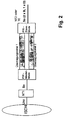
- FIG. 2 shows a device for increasing the range of the transmission path between functional units of the ISDN subscriber line in relation to an S o interface.
- a device for protocol conversion PW is arranged on the network side at interface S o , which communicates via two transmission channels with a device for protocol conversion PW on the terminal side and provides the interface S o on the terminal side.
- a switching system (NT2) or terminal devices (TE) can then be operated on the terminal side, for example.
- the device for protocol conversion PW in master mode always reactivates the S o interface when it is not active. It only transmits data when the S o interface is active.
- the device for protocol conversion PW in slave mode reactivates the S o interface when it is not active and the device is also receiving data from the master device. It deactivates the S o interface when it receives no data from the master device.
- FIG. 3 shows, analogously to FIG. 2, a device for increasing the range of the transmission path between functional units of the ISDN subscriber line in relation to an ISDN interface.
- a protocol converter is assigned to each transmission channel on the terminal side. This makes it possible to conduct communication separately according to B1 and B2 channel over 64 kbit / s each at separate locations.
- the microcomputers (6) of the protocol converter (PW) recognize the state of the ISDN interface S 0 by evaluating the D-channel information.
- the microcomputer (6) takes over data from the interface module (2), which in this mode of operation is connected as an interface for the exchange of digital, serial data, and transfers it to the further interface module (2) for transmission on the transmission channel X1.
- the microcomputer (6) switches off the interface module (2) which is switched for the exchange of digital, serial data.
- the device for protocol conversion then works as described in FIG. 2.
Landscapes
- Engineering & Computer Science (AREA)
- Computer Networks & Wireless Communication (AREA)
- Communication Control (AREA)
- Synchronisation In Digital Transmission Systems (AREA)
- Data Exchanges In Wide-Area Networks (AREA)
- Use Of Switch Circuits For Exchanges And Methods Of Control Of Multiplex Exchanges (AREA)
- Telephonic Communication Services (AREA)
Abstract
Claims (12)
- Procédé pour l'augmentation de la portée de la voie de transmission entre des unités fonctionnelles d'un poste d'abonné RNIS avec une bande passante minimisée et en rapport avec une interface RNIS, avec utilisation d'un moyen de transmission,les données codées, spécifiques au RNIS et entrant à l'interface RNIS étant, du côté émetteur, converties en données codées binairement au moyen d'un convertisseur de code et séparées suivant des informations de canaux B et d'un canal D,les données entrantes étant préparées, traitées et finalement amenées au moyen de transmission et transférées au côté récepteur par l'intermédiaire de ce moyen de transmission, à une cadence dérivée de la cadence d'horloge du réseau RNIS,les cadences spécifiques au RNIS et nécessaires à la communication de l'émetteur et du récepteur étant récupérés du côté récepteur au moyen d'un dispositif de récupération de cadence à partir de la séquence temporelle des bits de données transférés,les bits de données reçus étant analysés, traités et amenés au convertisseur de code en fonction de la cadence du réseau RNIS récupéré et les données codées binairement étant converties en données codées spécifiques au RNIS, caractérisé en ce queA) les données entrant des canaux B sont séparées suivant des données du canal B1 et du canal B2, des sections de même longueur pour les données du canal B1 et du canal B2 sont préparées dans un dispositif de mémorisation, analysées pour vérifier la similitude des données, les données identiques étant compressées, et finalement amenées au moyen de transmission à une cadence ou un rythme pas à pas dérivé(e) de la cadence ou du rythme du réseau RNIS, avec alternance des données du canal B1 et du canal B2, et transmises au côté récepteur par l'intermédiaire de ce moyen de transmission.B) des blocs sont formés à partir des données entrant du canal D, la transmission des données du canal B est interrompue et, au lieu des données du canal B, les blocs du canal D sont amenés de préférence au moyen de transmission pour le transfert vers le côté récepteur,C) les caractéristiques des données reçues sont analysées octet par octet, les blocs du canal D identifiés sont séparés et amenés directement au convertisseur de code, les données compressées identifiées du canal B sont séparées et mémorisées temporairement dans un dispositif de mémorisation avec les données identifiées du canal B, en étant séparées suivant des données du canal B1 et du canal B2, et amenées au convertisseur de code en fonction du rythme ou de la cadence récupéré(e), et les données codées binairement sont converties en données codées spécifiques au RNIS.
- Procédé suivant la revendication 1, caractérisé en ce que la compression et la décompression des données du canal B sont réalisées de telle manière qu'à l'apparition de signes identiques un bloc de compression du canal B est formé avec un compteur de répétition et un code ou un identifiant pour le canal respectif et qu'à la décompression les répétitions de signes identifiées sont à nouveau séparées.
- Procédé suivant les revendications 1 et 2, caractérisé en ce que les sections du canal B sont formées avec une longueur fixe, la longueur minimale des blocs du canal D et des blocs de compression du canal B étant ¼ des sections du canal B, et les blocs du canal D présentant une longueur multiple de la longueur minimale.
- Procédé suivant les revendications 1 à 3, caractérisé en ce que, à la formation des blocs du canal D et des blocs de compression du canal B, la transmission des sections du canal B est interrompue à un point ou endroit divisible par 4 et que ces sections, au lieu des sections du canal B, sont transférées au moyen de transmission pour le transfert au côté récepteur, les blocs du canal D étant préférés.
- Procédé suivant la revendication 3, caractérisé en ce qu'un bloc de compression du canal B, servant d'aide pour la synchronisation sur la limite des octets, est aussi formé lorsque le flux de données n'en est pas réduit.
- Procédé suivant la revendication 1, caractérisé en ce que, pendant les périodes où un canal B1 et/ou B2 n'est pas utilisé pour la transmission, il n'y a pas d'acheminement de données du canal B vers le moyen de transmission.
- Procédé suivant la revendication 1, caractérisé en ce que, pendant les périodes où l'interface RNIS n'est pas active, des données sérielles et numériques sont échangées sans conversion de code par l'intermédiaire du moyen de transmission.
- Procédé suivant la revendication 1, caractérisé en ce que la transmission des données est réalisée par l'intermédiaire d'un ou de plusieurs canaux du moyen de transmission.
- Dispositif pour la conversion de protocoles pour l'augmentation de la portée de la voie de transmission entre des unités fonctionnelles d'un poste d'abonné RNIS en rapport avec une interface RNIS, constitué d'un module d'interface RNIS (1) avec un circuit intégré ISAC à registre ; d'un micro-ordinateur (6) avec un microprocesseur, avec une mémoire ROM pour la mémorisation du code du programme et une mémoire RAM comme mémoire de travail ; d'un ou de plusieurs modules d'interface (2) avec des modules d'entrée et de sortie sériels SIO pour le canal de transmission X ; d'un module générateur de rythme ou de cadence (3) ; d'un commutateur de mode (5) ; d'une alimentation en courant (4) ainsi que de connexions électriques correspondantes et d'un bus pour l'échange d'adresses et de données, le module d'interface RNIS (1) étant apte à convertir aussi bien des données codées spécifiques au RNIS en données codées binairement qu'inversement des données codées binairement en données codées spécifiques au RNIS,le commutateur (5) de réglage du mode agissant sur l'alimentation en courant (4), sur le module d'interface RNIS (1) et sur le module (3) générateur de rythme ou de cadence et présentant une fonction de commutation supplémentaire pour l'exploitation pour la conversion de protocoles par l'intermédiaire d'un ou de plusieurs modules d'interface (2) et pour l'attribution de rythmes ou de cadences émetteurs correspondants,l'alimentation en courant (4) alimentant le circuit en tension et étant apte, lorsque le convertisseur de protocoles fonctionne en mode esclave, à fournir la tension d'alimentation pour des terminaux ne dépendant pas du secteur,et le module générateur de rythme (3) étant connecté au module d'interface RNIS (1), au module d'interface (2) pour la connexion au canal de transmission (X) ainsi qu'au micro-ordinateur (6), et étant apte à récupérer les rythmes ou cadences spécifiques au RNIS et nécessaires à la communication entre l'émetteur et le récepteur à partir de la séquence temporelle des bits de données transmis,le micro-ordinateur (6) étant connecté au circuit intégré ISAC du module d'interface RNIS (1) ainsi qu'aux modules d'entrée et de sortie SIO des modules d'interface (2) par l'intermédiaire du bus, et le processeur dans le micro-ordinateur (6) commandant le fonctionnement des éléments tels que le module générateur de cadence ou de rythme (3), le circuit intégré ISAC du module d'interface RNIS (1) et les modules SIO dans les modules d'interface (2), par le réglage des registres prévus dans ces éléments, demandant l'état de ces élément par l'intermédiaire des registres de ces éléments et échangeant des données avec ces éléments, caractérisé en ce que le micro-ordinateur (7) est apteA) à séparer les données entrant des canaux B suivant des données du canal B1 et du canal B2, à mémoriser temporairement des sections de même longueur pour les données des canaux B1 et B2 dans la mémoire RAM, à vérifier la similitude des données, à compresser des données identiques et finalement à les amener au module d'interface (2), à un rythme pas à pas dérivé du rythme du réseau RNIS et avec alternance des données du canal B1 et des données du canal B2, pour la transmission par l'intermédiaire du canal de transmission X,B) à former des blocs à partir des données entrant du canal D, à interrompre la transmission des données du canal B et à amener les blocs du canal D, au lieu des données du canal B, de préférence au SIO adressé dans le module d'interface (2) pour la transmission au côté récepteur,C) à analyser les caractéristiques des données reçues octet par octet, à séparer les blocs du canal D identifiés, à les amener directement au registre du circuit intégré ISAC du module d'interface RNIS (1), à séparer les données compressées du canal B et à les mémoriser temporairement dans la mémoire RAM avec les données du canal B identifiées, séparées en données du canal B1 et du canal B2, et à les amener au circuit intégré ISAC du module d'interface RNIS (1) en fonction du rythme récupéré.
- Dispositif suivant la revendication 9, caractérisé en ce que le canal de transmission X est constitué d'un canal ou de plusieurs canaux.
- Dispositif pour la conversion de protocoles suivant la revendication 10, caractérisé en ce que le canal de transmission X est constitué de plusieurs canaux individuels et en ce que le dispositif pour la conversion de protocoles présente plusieurs modules d'interfaces (2), la connexion d'au moins un module d'interface (2) étant commutée comme interface pour l'échange de données numériques sérielles et permettant l'échange de données numériques sérielles pendant les périodes pendant lesquelles l'interface RNIS n'est pas active, par l'intermédiaire du canal de transmission respectivement connecté.
- Dispositif pour la réalisation du procédé suivant la revendication 1 ainsi que suivant une ou plusieurs des revendications 9 à 11, caractérisé en ce qu'il est constitué d'équipements connectés aux interfaces RNIS du côté terminal et du côté réseau pour la conversion de protocoles et de canaux de transmission attribués à ces équipements comprenant le dispositif de transmission et le milieu de transmission, et en ce que les équipements de conversion de protocoles communiquent entre eux par l'intermédiaire du canal de transmission attribué, et en ce que les équipements de conversion de protocoles sont configurés aussi bien en mode maítre qu'en mode esclave ou en mode maítre ou mode esclave, l'équipement connecté du côté réseau pour la conversion de protocoles étant commuté en mode maítre et l'équipement connecté du côté terminal pour la conversion de protocoles étant commuté en mode esclave.
Applications Claiming Priority (5)
| Application Number | Priority Date | Filing Date | Title |
|---|---|---|---|
| DE19637302 | 1996-09-11 | ||
| DE19637302A DE19637302A1 (de) | 1996-09-13 | 1996-09-13 | Verfahren und Vorrichtung zur Vergrößerung der Reichweite des Übertragungsweges zwischen Funktionseinheiten des ISDN-Teilnehmeranschlusses mit einer minimierten Bandbreite |
| US08/898,277 US6181709B1 (en) | 1996-09-11 | 1997-07-22 | Method and apparatus for the enlargement of the range of the transmission channel between functional groups of the ISDN-user interface with a minimized bandwidth |
| US898277 | 1997-07-22 | ||
| PCT/DE1997/002042 WO1998011755A2 (fr) | 1996-09-13 | 1997-09-12 | Procede et dispositif pour augmenter la portee de la voie de transmission entre des unites fonctionnelles du poste d'abonne rnis avec une bande passante minimisee |
Publications (2)
| Publication Number | Publication Date |
|---|---|
| EP0925708A2 EP0925708A2 (fr) | 1999-06-30 |
| EP0925708B1 true EP0925708B1 (fr) | 2001-03-14 |
Family
ID=26029333
Family Applications (1)
| Application Number | Title | Priority Date | Filing Date |
|---|---|---|---|
| EP97944704A Expired - Lifetime EP0925708B1 (fr) | 1996-09-13 | 1997-09-12 | Procede et dispositif pour augmenter la portee de la voie de transmission entre des unites fonctionnelles du poste d'abonne rnis avec une bande passante minimisee |
Country Status (7)
| Country | Link |
|---|---|
| EP (1) | EP0925708B1 (fr) |
| JP (1) | JP2001503209A (fr) |
| AU (1) | AU719803B2 (fr) |
| CA (1) | CA2265555A1 (fr) |
| IL (1) | IL121739A (fr) |
| NO (1) | NO990506L (fr) |
| WO (1) | WO1998011755A2 (fr) |
Family Cites Families (6)
| Publication number | Priority date | Publication date | Assignee | Title |
|---|---|---|---|---|
| DE3431423A1 (de) * | 1984-08-27 | 1986-03-06 | Telefonbau Und Normalzeit Gmbh, 6000 Frankfurt | Verfahren zur uebertragung von digitalen informationen auf anschlussleitungen von fernmelde-, insbesondere fernsprechvermittlungsanlagen |
| DE4131062C1 (fr) * | 1991-09-18 | 1992-11-05 | Siemens Ag, 8000 Muenchen, De | |
| US5412660A (en) * | 1993-09-10 | 1995-05-02 | Trimble Navigation Limited | ISDN-to-ISDN communication via satellite microwave radio frequency communications link |
| DE4407214C1 (de) * | 1994-03-06 | 1995-08-03 | Dtm Data Telemark Gmbh | Verfahren und Vorrichtung zur Vergrößerung der Reichweite des Übertragungsweges zwischen Funktionseinheiten des ISDN-Teilnehmeranschlusses |
| DE19506906A1 (de) * | 1994-03-06 | 1996-09-05 | Dtm Data Telemark Gmbh | Verfahren und Vorrichtung zur Vergrößerung der Reichweite des Übertragungsweges zwischen Funktionseinheiten des ISDN-Teilnehmeranschlusses |
| JPH07273802A (ja) * | 1994-03-30 | 1995-10-20 | Mitsubishi Electric Corp | Lan間通信装置及びlan間通信送信装置及びlan間通信受信装置 |
-
1997
- 1997-09-11 IL IL12173997A patent/IL121739A/xx not_active IP Right Cessation
- 1997-09-12 AU AU46147/97A patent/AU719803B2/en not_active Ceased
- 1997-09-12 CA CA002265555A patent/CA2265555A1/fr not_active Abandoned
- 1997-09-12 EP EP97944704A patent/EP0925708B1/fr not_active Expired - Lifetime
- 1997-09-12 WO PCT/DE1997/002042 patent/WO1998011755A2/fr not_active Ceased
- 1997-09-12 JP JP10513154A patent/JP2001503209A/ja active Pending
-
1999
- 1999-02-04 NO NO990506A patent/NO990506L/no not_active Application Discontinuation
Also Published As
| Publication number | Publication date |
|---|---|
| JP2001503209A (ja) | 2001-03-06 |
| EP0925708A2 (fr) | 1999-06-30 |
| IL121739A (en) | 2001-01-11 |
| AU4614797A (en) | 1998-04-02 |
| WO1998011755A2 (fr) | 1998-03-19 |
| CA2265555A1 (fr) | 1998-03-19 |
| NO990506D0 (no) | 1999-02-04 |
| IL121739A0 (en) | 1998-04-05 |
| NO990506L (no) | 1999-04-20 |
| AU719803B2 (en) | 2000-05-18 |
| WO1998011755A3 (fr) | 1998-07-16 |
Similar Documents
| Publication | Publication Date | Title |
|---|---|---|
| DE3689115T2 (de) | Übertragungseinrichtung. | |
| DE69434503T2 (de) | Mobiles Funk-Übermittlungssystem | |
| DE68914529T2 (de) | Paketvermittlungssystem für eine ISDN-Vermittlungseinrichtung mit verteilter Steuerung. | |
| EP0668706A2 (fr) | Terminal de réseau | |
| DE69103551T2 (de) | Mehrfachmedien ISDN Kommunikationssystem. | |
| DE4131062C1 (fr) | ||
| DE2915488A1 (de) | Schaltungsanordnung zur steuerung der uebertragung von digital-signalen, insbesondere pcm-signalen, zwischen anschlusstellen eines zeitmultiplex-fernmeldenetzes, insbesondere pcm-zeitmultiplex-fernmeldenetzes | |
| DE4321481C1 (de) | Fernsteuerbares Kommunikationssystem mit einem Fernübertragungsmodul | |
| EP0795975A2 (fr) | Dispositif pour réduire la capacité de transmission de données | |
| EP0741500B1 (fr) | Système de télécommunication et dispositif de terminaison de réseau correspondant | |
| DE19637302A1 (de) | Verfahren und Vorrichtung zur Vergrößerung der Reichweite des Übertragungsweges zwischen Funktionseinheiten des ISDN-Teilnehmeranschlusses mit einer minimierten Bandbreite | |
| DE4407214C1 (de) | Verfahren und Vorrichtung zur Vergrößerung der Reichweite des Übertragungsweges zwischen Funktionseinheiten des ISDN-Teilnehmeranschlusses | |
| EP0734186A2 (fr) | Procédé pour commander un réseau d'accès ainsi qu'un réseau d'accès et un central pour cela | |
| DE3233221A1 (de) | Schaltungsanordnung zum uebertragen von signalen zwischen teilnehmeranschlussleitungen und wenigstens einer uebertragungsleitung einer dienstintegrierten fernmeldeanlage | |
| DE19958111A1 (de) | Verfahren zur Datenübertragung über mehrere parallele Datenübertragungsverbindungen | |
| EP0925708A2 (fr) | Procede et dispositif pour augmenter la portee de la voie de transmission entre des unites fonctionnelles du poste d'abonne rnis avec une bande passante minimisee | |
| EP1125469B1 (fr) | Systeme de communication comportant des appareils de communication en liaison avec une installation de communication par l'intermediaire d'un reseau de communication oriente paquets | |
| EP0333126B1 (fr) | Central de télécommunication privé pour transmission de signaux à large bande | |
| EP0749669B1 (fr) | Procede et dispositif destines a accroitre la portee de la voie de transmission entre des unites fonctionnelles de l'acces d'abonne au rnis | |
| EP0058760B1 (fr) | Circuit pour la connection d'émetteurs de signaux analogiques à des récepteurs de signaux analogiques par une central de commutation temporelle de données | |
| DE4304195C2 (de) | Vermittlungseinrichtung für dienstintegrierte und dienstspezifische Netze, die mindestens einer Zentral-Netz-Kontroll-Komponente und eine Schmalband-Vermittlungs-Komponente aufweist | |
| EP0231809B1 (fr) | Procédé pour l'intégration d'un ou de plusieurs modules à fonction supplémentaire dans des centraux téléphoniques ainsi que circuit d'accès pour réaliser le procédé | |
| EP0963134B1 (fr) | Méthode de transmission de données utilisateur dans un réseau numérique à intégration de services (RNIS) | |
| DE3225684A1 (de) | Abschlussschaltung fuer eine teilnehmereinrichtung in einem digitalen fernmeldesystem | |
| EP0522318A2 (fr) | Dispositif de commutation pour des signaux numériques en mode de transmission asynchrone et synchrone |
Legal Events
| Date | Code | Title | Description |
|---|---|---|---|
| PUAI | Public reference made under article 153(3) epc to a published international application that has entered the european phase |
Free format text: ORIGINAL CODE: 0009012 |
|
| 17P | Request for examination filed |
Effective date: 19990413 |
|
| AK | Designated contracting states |
Kind code of ref document: A2 Designated state(s): DE ES FR GB SE |
|
| RAP1 | Party data changed (applicant data changed or rights of an application transferred) |
Owner name: DICA TECHNOLOGIES AG |
|
| 17Q | First examination report despatched |
Effective date: 20000310 |
|
| GRAG | Despatch of communication of intention to grant |
Free format text: ORIGINAL CODE: EPIDOS AGRA |
|
| GRAH | Despatch of communication of intention to grant a patent |
Free format text: ORIGINAL CODE: EPIDOS IGRA |
|
| GRAG | Despatch of communication of intention to grant |
Free format text: ORIGINAL CODE: EPIDOS AGRA |
|
| GRAH | Despatch of communication of intention to grant a patent |
Free format text: ORIGINAL CODE: EPIDOS IGRA |
|
| GRAA | (expected) grant |
Free format text: ORIGINAL CODE: 0009210 |
|
| AK | Designated contracting states |
Kind code of ref document: B1 Designated state(s): DE ES FR GB SE |
|
| RIN1 | Information on inventor provided before grant (corrected) |
Inventor name: HELBIG, KLAUS Inventor name: WULST, NORBERT |
|
| REF | Corresponds to: |
Ref document number: 59703152 Country of ref document: DE Date of ref document: 20010419 |
|
| PG25 | Lapsed in a contracting state [announced via postgrant information from national office to epo] |
Ref country code: SE Free format text: LAPSE BECAUSE OF FAILURE TO SUBMIT A TRANSLATION OF THE DESCRIPTION OR TO PAY THE FEE WITHIN THE PRESCRIBED TIME-LIMIT Effective date: 20010614 |
|
| ET | Fr: translation filed | ||
| GBT | Gb: translation of ep patent filed (gb section 77(6)(a)/1977) |
Effective date: 20010629 |
|
| PG25 | Lapsed in a contracting state [announced via postgrant information from national office to epo] |
Ref country code: ES Free format text: LAPSE BECAUSE OF FAILURE TO SUBMIT A TRANSLATION OF THE DESCRIPTION OR TO PAY THE FEE WITHIN THE PRESCRIBED TIME-LIMIT Effective date: 20010927 |
|
| REG | Reference to a national code |
Ref country code: GB Ref legal event code: IF02 |
|
| PLBE | No opposition filed within time limit |
Free format text: ORIGINAL CODE: 0009261 |
|
| STAA | Information on the status of an ep patent application or granted ep patent |
Free format text: STATUS: NO OPPOSITION FILED WITHIN TIME LIMIT |
|
| 26N | No opposition filed | ||
| PGFP | Annual fee paid to national office [announced via postgrant information from national office to epo] |
Ref country code: FR Payment date: 20020830 Year of fee payment: 6 |
|
| PGFP | Annual fee paid to national office [announced via postgrant information from national office to epo] |
Ref country code: DE Payment date: 20030804 Year of fee payment: 7 |
|
| PGFP | Annual fee paid to national office [announced via postgrant information from national office to epo] |
Ref country code: GB Payment date: 20030806 Year of fee payment: 7 |
|
| PG25 | Lapsed in a contracting state [announced via postgrant information from national office to epo] |
Ref country code: FR Free format text: LAPSE BECAUSE OF NON-PAYMENT OF DUE FEES Effective date: 20040528 |
|
| REG | Reference to a national code |
Ref country code: FR Ref legal event code: ST |
|
| PG25 | Lapsed in a contracting state [announced via postgrant information from national office to epo] |
Ref country code: GB Free format text: LAPSE BECAUSE OF NON-PAYMENT OF DUE FEES Effective date: 20040912 |
|
| PG25 | Lapsed in a contracting state [announced via postgrant information from national office to epo] |
Ref country code: DE Free format text: LAPSE BECAUSE OF NON-PAYMENT OF DUE FEES Effective date: 20050401 |
|
| GBPC | Gb: european patent ceased through non-payment of renewal fee |
Effective date: 20040912 |