EP0925801B1 - Ballonkatheter mit einem spiralfederförmigen Übergangsbereich - Google Patents
Ballonkatheter mit einem spiralfederförmigen Übergangsbereich Download PDFInfo
- Publication number
- EP0925801B1 EP0925801B1 EP98310615A EP98310615A EP0925801B1 EP 0925801 B1 EP0925801 B1 EP 0925801B1 EP 98310615 A EP98310615 A EP 98310615A EP 98310615 A EP98310615 A EP 98310615A EP 0925801 B1 EP0925801 B1 EP 0925801B1
- Authority
- EP
- European Patent Office
- Prior art keywords
- catheter
- distal end
- transition
- assembly
- coil
- Prior art date
- Legal status (The legal status is an assumption and is not a legal conclusion. Google has not performed a legal analysis and makes no representation as to the accuracy of the status listed.)
- Expired - Lifetime
Links
Images
Classifications
-
- A—HUMAN NECESSITIES
- A61—MEDICAL OR VETERINARY SCIENCE; HYGIENE
- A61M—DEVICES FOR INTRODUCING MEDIA INTO, OR ONTO, THE BODY; DEVICES FOR TRANSDUCING BODY MEDIA OR FOR TAKING MEDIA FROM THE BODY; DEVICES FOR PRODUCING OR ENDING SLEEP OR STUPOR
- A61M25/00—Catheters; Hollow probes
- A61M25/0043—Catheters; Hollow probes characterised by structural features
- A61M25/005—Catheters; Hollow probes characterised by structural features with embedded materials for reinforcement, e.g. wires, coils, braids
- A61M25/0052—Localized reinforcement, e.g. where only a specific part of the catheter is reinforced, for rapid exchange guidewire port
-
- A—HUMAN NECESSITIES
- A61—MEDICAL OR VETERINARY SCIENCE; HYGIENE
- A61M—DEVICES FOR INTRODUCING MEDIA INTO, OR ONTO, THE BODY; DEVICES FOR TRANSDUCING BODY MEDIA OR FOR TAKING MEDIA FROM THE BODY; DEVICES FOR PRODUCING OR ENDING SLEEP OR STUPOR
- A61M25/00—Catheters; Hollow probes
- A61M25/0043—Catheters; Hollow probes characterised by structural features
- A61M25/005—Catheters; Hollow probes characterised by structural features with embedded materials for reinforcement, e.g. wires, coils, braids
-
- A—HUMAN NECESSITIES
- A61—MEDICAL OR VETERINARY SCIENCE; HYGIENE
- A61M—DEVICES FOR INTRODUCING MEDIA INTO, OR ONTO, THE BODY; DEVICES FOR TRANSDUCING BODY MEDIA OR FOR TAKING MEDIA FROM THE BODY; DEVICES FOR PRODUCING OR ENDING SLEEP OR STUPOR
- A61M25/00—Catheters; Hollow probes
- A61M25/0043—Catheters; Hollow probes characterised by structural features
- A61M2025/0063—Catheters; Hollow probes characterised by structural features having means, e.g. stylets, mandrils, rods or wires to reinforce or adjust temporarily the stiffness, column strength or pushability of catheters which are already inserted into the human body
-
- A—HUMAN NECESSITIES
- A61—MEDICAL OR VETERINARY SCIENCE; HYGIENE
- A61M—DEVICES FOR INTRODUCING MEDIA INTO, OR ONTO, THE BODY; DEVICES FOR TRANSDUCING BODY MEDIA OR FOR TAKING MEDIA FROM THE BODY; DEVICES FOR PRODUCING OR ENDING SLEEP OR STUPOR
- A61M25/00—Catheters; Hollow probes
- A61M25/01—Introducing, guiding, advancing, emplacing or holding catheters
- A61M2025/0183—Rapid exchange or monorail catheters
-
- A—HUMAN NECESSITIES
- A61—MEDICAL OR VETERINARY SCIENCE; HYGIENE
- A61M—DEVICES FOR INTRODUCING MEDIA INTO, OR ONTO, THE BODY; DEVICES FOR TRANSDUCING BODY MEDIA OR FOR TAKING MEDIA FROM THE BODY; DEVICES FOR PRODUCING OR ENDING SLEEP OR STUPOR
- A61M25/00—Catheters; Hollow probes
- A61M25/0043—Catheters; Hollow probes characterised by structural features
- A61M25/0054—Catheters; Hollow probes characterised by structural features with regions for increasing flexibility
-
- A—HUMAN NECESSITIES
- A61—MEDICAL OR VETERINARY SCIENCE; HYGIENE
- A61M—DEVICES FOR INTRODUCING MEDIA INTO, OR ONTO, THE BODY; DEVICES FOR TRANSDUCING BODY MEDIA OR FOR TAKING MEDIA FROM THE BODY; DEVICES FOR PRODUCING OR ENDING SLEEP OR STUPOR
- A61M25/00—Catheters; Hollow probes
- A61M25/10—Balloon catheters
- A61M25/104—Balloon catheters used for angioplasty
Definitions
- the present invention generally relates to a balloon catheter for conducting dilatation procedures within the vascular system and in conjunction with a guiding catheter within which the balloon catheter is slidably moved for positioning and treatment.
- the balloon catheter incorporates an elongated, high-strength cannula as its proximal tube component and has a distal end assembly which incorporates the balloon and which has a flexibility substantially greater than that of the proximal cannula.
- the proximal cannula and the distal end assembly are joined together by a transition assembly which includes an elongated coil.
- the coil When negotiating a tight curve during a medical procedure using the catheter system, the coil imparts a force on the guiding catheter which is relatively low so as to avoid unintentional dislodgement of the guiding catheter from its intended position, such as in the atrium of the heart.
- proximal catheter tube which is relatively stiff and of high strength so that the elongated proximal tube accepts and transmits column forces, as well as torsional forces, from the proximal end of the catheter which remains outside of the body and to the distal end portion of the catheter so that the latter is properly positioned for effecting the dilatation procedure.
- Proximal elongated tubes such as metal hypotubes have been proposed or used in the past. This type of stiff tubing does not extend the full length of the balloon catheter. In order to maneuver through tight turns and/or constricting passageways, the distal end portion of the catheter must be quite flexible.
- catheters of this general type have included a transitional section between a stiff hypotube type of component and a flexible distal end portion of the catheter.
- a primary component of these types of transitional section approaches is the incorporation of a rigid structure generally at the transition location, whereby the stiffness of the proximal hypotube is gradually reduced as same moves into the flexible distal portion of the catheter.
- a bridging wire is provided as a distally oriented extension of the hypotube, this being positioned within a transition section between the distal end of the hypotube and the proximal end of the distal end portion of the catheter which contains the balloon.
- the bridge wire or the like creates difficulties when the balloon catheter must be passed through a tightly curved portion of the guiding catheter.
- the bridge wire There is a strong tendency for the bridge wire to transfer a bending force to the walls of the guiding catheter, due to the stiffness of the bridging wire, which force transfer typically increases when the tightness of the curve which must be navigated increases.
- the present invention concentrates on the structure of a transition section between an elongated stiff proximal tube and a flexible distal portion.
- European Patent Application No. 0 608 853 which is regarded as closest prior art, discloses a vascular dilatation instrument and catheter comprising an outer tube, an inner tube extending through the outer tube, and an inflatable member having one end attached to the inner tube and another end attached to the outer tube.
- the outer tube includes a superelastic or pseudoelastic metal tube and a synthetic resin tube covering the metal tube, the metal tube having a distal zone aprovided with a slit so that the distal zone is more flexible and deformable than the remainder of the metal tube.
- United States Patent No. 4,917,666 discloses a steerable thru-lumen catheter comprising a first flexible tubular member comprising a spring coil body defining a lumen, and having a flexible covering thereon, a second tubular member extending through the first tubular member and having one or more lumens therethrough, a dilatation balloon, and control means attached to the proximal end of the dilatation catheter.
- the control means and the dilatation catheter are configured so that when the control means is rotated, the dilatation catheter itself rotates to cause the distal end of the dilatation catheter to rotate.
- European Patent Application No. 0 715 863 discloses a catheter which uses a stiffener ribbon wound within the catheter body to create a catheter having controllable stiffness.
- the stiffener ribbon is bonded to a flexible outer tubing member so as to produce a flexible thin wall catheter section.
- a balloon dilatation catheter comprising: an elongated, high-strength proximal cannula having a proximal end, a distal end, and a lumen therethrough; a generally tubular distal end assembly having a guidewire passage lumen, a balloon member, and an inflation lumen in fluid passing communication with said lumen of the proximal cannula, said inflation lumen opening into said balloon, said distal end assembly having a flexibility greater than that of the proximal cannula; a coil transition assembly which is positioned between and which longitudinally connects said distal end assembly to said proximal cannula and provides flexible bending strain relief thereat, said coil transition assembly including a coil member having an external surface and a transition tube engaging said external surface of the coil member, said transition tube having an axial length at least as long as that of the coil member; a guidewire port generally at a location at which said coil transition assembly is secured to said distal end assembly;
- the coil transition assembly provides flexible bending strain relief.
- This balloon dilatation catheter is used in combination with a guiding catheter; the balloon dilatation catheter is able to smoothly follow sharp curves of the guiding catheter which are typically encountered during a dilatation procedure such as an angioplasty.
- the coil transition assembly imparts a force on the guiding catheter which is so low as to avoid dislodgement of the guiding catheter from its intended position within the vascular system when the dilatation catheter is moved within the guiding catheter.
- the transition section readily bends in an arc, thereby minimizing the force applied to the guiding catheter and avoiding dislodgement of the guiding catheter from the position at which it had been set by the physician.
- Another object of this invention is to provide a balloon dilatation catheter which moves linearly forwardly inside of a guiding catheter without undesired coil flexing which could hinder transmission of forces from the proximal end of the catheter which is outside of the body to the distal end of the catheter.
- Another object of the present invention is to provide an improved balloon dilatation catheter and guiding catheter combination which reduces the chance of having the guiding catheter become dislodged from the atrium during an angioplasty procedure.
- Another object of this invention is to provide a balloon dilatation catheter having a transition section which reduces the incidence of kinking thereat.
- Another object of the present invention to provide an improved balloon dilatation catheter and guiding catheter combination which exhibits an advantageous ease of tracking and lower tracking force due to having a coil transition which forms to the shape of the guiding catheter when that transition section moves through the guiding catheter.
- Another object of the present invention is to provide a transition section for a balloon dilatation catheter which provides a relatively larger cross-sectional area for passage of balloon inflation media therethrough during balloon inflation and deflation.
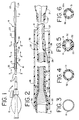
- a preferred balloon dilatation catheter is generally designated in FIG. 1 by reference numeral 11. It includes a hub assembly 12 of generally known structure for manipulating the catheter from a location outside of the body in a manner which is generally known in the art. An elongated, high strength proximal cannula 13 is attached to the hub assembly by a suitable structure and approach. A distal end assembly, generally designated at 14, provides the distal portion of the catheter. A transition assembly, generally designated at 15, connects the flexible distal end assembly 14 to the proximal cannula 13. A guiding catheter 16 is generally depicted in FIG. 2 in sliding engagement with the balloon dilatation catheter.
- proximal cannula 13 it is preferably made of a hypotube, typically made of metal. Especially stiff polymers can also be used. Hypotubes include those made of stainless steel, other stiff alloys available for use within the body, nickel-titanium alloys such as Nitinol®, and the like.
- the proximal cannula incorporates a material and structure which provides excellent load-bearing properties, including high column strength and excellent torqueability. Properties such as these permit the physician to manipulate the substantial proximal length of the catheter while the catheter is inserted within and through the vascular system of the patient. Such a high-strength cannula also provides exceptionally responsive movement of the more distal portions of the catheter in response to movements such as twisting and short longitudinal movements in and out within the vascular system.
- the length of the elongated cannula plus the hub assembly is between about 100 cm and about 120 cm.
- a typical balloon dilatation catheter in accordance with the invention has a total length, from the hub assembly to the distal tip of about 140 cm to about 160 cm.
- proximal cannula of a material such as stainless steel or other metal alloy or especially strong polymer is that these materials provide high strength with a minimum of wall thickness.
- Such thin-walled cannulas provide a greater cross-sectional area than do thicker walled tubes, thereby facilitating flow therethrough.
- the illustrated distal end assembly includes a balloon member 21 which is made of a material suitable for a dilatation balloon and in accordance with an appropriate molding approach for that material.
- the balloon member 21 is securely attached to an outer body tube 22, which outer body tube is attached at its other end to the transition assembly 15.
- Distal end assemblies can incorporate dual-lumen tubes, for example.
- the illustrated distal end assembly has a so-called coaxial structure. This coaxial structure includes the outer body tube 22 and an inner body tube or guidewire lumen 23. This type of coaxial structure is generally known.
- a distal leg portion 24 of the balloon is secured to a distal portion of the inner body tube.
- the distal end assembly 14 terminates in a distal tip 25.
- a typical distal end assembly has a length of several centimeters, for example between about 20 cm and about 30 cm.
- Distal end assembly 14 also includes a guidewire port 26 at its proximal end.
- the inner body tube is positioned at this guidewire port so that its proximal opening 27 accommodates a guidewire 28.
- the guidewire lumen 23 and thus the balloon dilatation catheter 11 will be slidably moved with respect to the guidewire, after the guidewire has been inserted to the desired location within the vascular system or the like. Operation of the equipment in this regard is generally known.
- This coil member 31 is typically helically wound and can be constructed of flat ribbon wire or wire that is generally round in cross-section.
- the flat ribbon cross-section is preferred.
- the coil member 31 can be made of materials such as those which are suitable for the proximal cannula 13. Stainless steel is particularly preferred.
- Coil member 31 is preferably wound so as to provide a very small gap between adjacent turns of the coil. A gap of about 0.005 inch (about 0.01 mm), typically not more than about 0.001 inch (about 0.025 mm), is typical. This minimizes the risk of coil turn overlap as the coil bends when passing through a curved path.
- the transition tube 32 is made of a polymer material. If the tube has good strength attributes, then a less-rigid coil can be provided, including one having a round cross-section and/or having turns which are somewhat spaced apart. Whatever the precise structure utilized, the transitional assembly 15 provides a flexible transition between the generally rigid proximal cannula and the generally flexible distal end assembly.
- the inner diameter of the tube closely conforms to the outer diameter of the coil member 31, while allowing sliding between these surfaces of the coil and tube so they slidably engage each other during bending along a curve of the inserted guiding catheter.
- the coil member has a tapered location 33
- the transition tube 32 has its own generally correspondingly shaped and sized tapered location 34.
- the coil member 31 is wound on a mandrel by means of a coil winder such that its outer diameter is somewhat less than the inner diameter of the tubing for preparing the transition tube 32.
- the mandrel-supported wound coil is inserted into the inner diameter or lumen of the tubing, and the mandrel is removed.
- the tube is assembled onto the cannula 13 to form a seal area generally designated at 35.
- the proximal end 36 of the transition tube is sealed onto the distal end of the proximal cannula 13.
- the assembly can be practiced by suitable means including the use of adhesives and/or heat or other suitable procedure or means.
- a distal end 37 of the transition tube 32 extends beyond the distal end of the coil member 31, and this distal end 37 is secured to the proximal end portion of the distal end assembly 14 at a seal area, generally designated at 38.
- the guidewire port 26 is formed when the proximal end portion of the guidewire lumen 23 is sealed between the distal end portion 37 of the transition tube and the proximal end portion of the outer body tube 22.
- this seal area 38 is facilitated by having the outer body tube 22 and the transition tube 32 made of materials which are readily heat sealed together.
- the outer body tube can be made, for example, of a nylon material or of a polyamide material, such as an extruded nylon homopolymer or copolymer or blend of homopolymer and copolymer.
- at least a portion of the outer surface of the transition tube 32 is made of a nylon material and can be made of the same nylon material or polyamide material as the material out of which the outer body tube 22 is made.
- the inner surface of the transition tube 32 can be made of a material such as a polyethylene which more readily bonds to the proximal cannula than does a polyamide or nylon material.
- the cannula is made of stainless steel
- the outer body tube 22 is made of nylon 12.
- the transition tube 32 is preferably made of two different materials. The preferred manner of accomplishing this desired result is to have the transition tube be a coextrusion. The exemplified coextrusion provides an inner surface of polyethylene, which bonds well to stainless steel, and an external surface of a nylon 12 material or other material which readily bonds to the distal end assembly.
- a typical guidewire lumen 23 will accommodate a guidewire 28 having an outer diameter of 0.0014 inch (0.036 mm) when the dilatation catheter is of the PTCA type.
- the guidewire lumen will accommodate a guidewire of a larger outer diameter, usually on the order of 0.0018 inch (0.046 mm).
- the coil member 31 is made of a flat stainless steel wire, the thickness of the flat wire will vary between about 0.001 inch and about 0.005 inch (about 0.025 mm to about 0.13 mm), preferably between about 0.002 inch and about 0.004 inch (about 0.05 mm to about 0.1 mm).
- FIG. 6 depicts an alternative embodiment for the transition assembly.
- the coil member 31 is sandwiched between the transition tube members.
- An inner transition tube 39 is provided in addition to the outer transition tube 32a.
- the outer transition tube 32a can be especially thin in view of the provision of the inner transition tube 39 as well. With this arrangement, the coil member 31 is sandwiched between the transition tubing.
- FIG. 2 illustrates a coil member 31 which incorporates a distally directed extension 41 which helps to protect and strengthen the proximal end portion of the distal end assembly 14 without unduly stiffening the area of joining between the transition assembly and the distal end assembly, including the seal area 38.
- this extension 41 is formed by leaving uncoiled a distal portion of the wire from which the coil is wound. This single-piece manner of providing the coil member and the extension avoids any assembly needs, for example. Provision of the distally directed extension 41 also assists in avoiding kinking at this joining location where the relatively thick seal area 38 is directly adjacent to thinner tubing lengths. It is also possible to provide the distally directed extension at the general location of extension 41 and which is assembled onto the transition assembly, such as by welding. Such a distally directed extension can be of a tapered variety which reduces in thickness in the distal direction. Alternatively, additional tubing components could be added in this general area.
- the transition assembly has a total length of between about 10 cm and about 35 cm, preferably between about 12 cm and about 20 cm.
- the length of the coil member 31 can range between about 5 cm and about 30 cm, preferably between about 8 cm and about 18 cm.
- the guiding catheter 16 and the balloon dilatation catheter 11 can comprise a combination of catheters which are used during balloon dilatation procedures such as angioplasty, typically in association with a guidewire 28.
- the interaction of this combination of catheters is rendered more beneficial to the physician practicing a dilatation and/or angioplasty procedure.
- the transition assembly discussed in accordance with the present invention there is a tendency for difficulties to arise when attempting to pass the balloon dilatation catheter through the guiding catheter at a location where the guiding catheter has a tight curve at a location along its length when within the vascular system and/or heart.
- An approach which does not follow the transition of the present invention incorporates a stiffening wire at a transition location of a balloon dilatation catheter.
- that stiffening wire takes a bend (such as in the aortic arch) it imparts a force on the guiding catheter due to the resistance to bending which is exhibited by such a stiffening wire.
- This force has a tendency to cause the guiding catheter to dislodge from a desired location, such as from the atrium.
- the transition assembly of the present invention is able to navigate such a tight bend or curve more easily and thus imparts a much lower force onto the wall of the guiding catheter. This is a relatively low force which is substantially lower than that for a catheter having a stiffening wire at the transition location rather than the transition assembly of the present invention.
Landscapes
- Health & Medical Sciences (AREA)
- Life Sciences & Earth Sciences (AREA)
- Biophysics (AREA)
- Pulmonology (AREA)
- Engineering & Computer Science (AREA)
- Anesthesiology (AREA)
- Biomedical Technology (AREA)
- Heart & Thoracic Surgery (AREA)
- Hematology (AREA)
- Animal Behavior & Ethology (AREA)
- General Health & Medical Sciences (AREA)
- Public Health (AREA)
- Veterinary Medicine (AREA)
- Media Introduction/Drainage Providing Device (AREA)
Claims (9)
- Ballondilatationskatheter (11) umfassend:dadurch gekennzeichnet, dass er weiter umfasst:eine verlängerte proximale Kanüle (13) mit einer großen Stärke und einem proximalen Ende, einem distalen Ende und einem Hohlraum dazwischen;eine im Allgemeinen röhrenförmige distale Endanordnung (14) mit einem Führungsdrahtdurchtrittshohlraum (23), einem Ballonelement (21) und einem aufblasbaren Hohlraum (22) in Flüssigverbindung mit dem Hohlraum der proximalen Kanüle, wobei sich der aufblasbare Hohlraum in den Ballon (21) öffnet, die distale Endanordnung (14) eine größere Flexibilität aufweist als die proximale Kanüle (13); eine Spiralfederübergangsanordnung (15), die zwischen der distalen Endanordnung (14) und der proximalen Kanüle (13) positioniert ist und diese in Längsrichtung miteinander verbindet und dort eine Biegeverformungsaussparung bereitstellt, wobei die Spiralfederübergangsanordnung (15) ein Spiralfederelement (31) mit einer äußeren Oberfläche und einem Übergangsrohr (32) umfasst, das in die äußere Oberfläche des Spiralfederelementes (31) eingreift, wobei das Übergangsrohr (32) eine axiale Länge aufweist, die wenigstens so lange ist wie die des Spiralfederelementes (31);eine Führungsdrahtöffnung (26), im Allgemeinen an einer Stelle, an der die Spiralfederübergangsanordnung (15) mit der distalen Endanordnung (14) verbunden ist; undeine distal gerichtete Verlängerung (41) von dem Spiralfederelement, wobei sich die Verlängerung zwischen dem Spiralfederelement (31) und einem proximalen Abschnitt der distalen Endanordnung (14) befindet.
- Dilatationskatheter nach Anspruch 1, wobei das Spiralfederelement (31) der Übergangsanordnung (15) ein Banddraht ist, der helikal zu dem Spiralfederelement gewunden ist.
- Dilatationskatheter nach Anspruch 1, wobei das Spiralfederelement (31) der Übergangsanordnung (15) ein Draht mit einem kreisförmigen Querschnitt ist, der zu dem Spiralfederelement gewunden ist.
- Dilatationskatheter nach einem der Ansprüche 1 bis 3, wobei das Spiralfederelement (31) eine Vielzahl von Windungen enthält, die eng räumlich voneinander getrennt sind, so dass sich eine Spiralfeder mit geringen Abständen ergibt.
- Dilatationskatheter nach einem der Ansprüchen 1 bis 4, wobei sich das Übergangsrohr (32) der Spiralfederübergangsanordnung (14) proximal über das proximale Ende des Spiralfederelementes (31) hinaus erstreckt und an dem distalen Ende der proximalen Kanüle ( 13) befestigt ist.
- Dilatationskatheter nach einem der Ansprüche 1 bis 5, wobei sich ein distaler Endabschnitt des Übergangsrohres (32) über das distale Ende des Spiralfederelementes (31) hinaus erstreckt und mit der distalen Endanordnung (14) befestigt ist.
- Dilatationskatheter nach den Ansprüchen 5 und 6, wobei das Übergangsrohr (32) eine innere Oberfläche und eine äußere Oberfläche aufweist und wobei das distale Ende der proximalen Kanüle (13) an der inneren Oberfläche des Übergangsrohres (32) befestigt ist, während das proximale Ende der distalen Endanordnung (14) an der äußeren Oberfläche des Übergangsrohres (32) befestigt ist.
- Dilatationskatheter nach Anspruch 7, wobei das Übergangsrohr (32) ein coextrudiertes Rohr mit einer inneren Oberfläche aus einem Material ist, das leicht an der proximalen Kanüle (13) befestigbar ist, und eine äußere Oberfläche aufweist, die leicht mit der distalen Endanordnung (14) befestigbar ist.
- Eine Kombination eines Ballon-Dilatationskatheters und Führungskatheters (16), umfassend:einen Führungskatheter (16) mit einer Länge, die für Dilatationsverfahren geeignet ist, wobei der Führungskatheter (16) ein Führungslumen mit einem Innendurchmesser hat; undein Ballon-Dilatationskatheter, wie er in irgendeinem vorhergehenden Anspruch erwähnt ist, einen Außendurchmesser hat, der kleiner als der Innendurchmesser des Führungskatheters (16) ist, um ein Verschieben des Ballon-Dilatationskatheters innerhalb des Führungslumens des Führungskatheters (16) zu ermöglichen.
Applications Claiming Priority (2)
| Application Number | Priority Date | Filing Date | Title |
|---|---|---|---|
| US996608 | 1997-12-23 | ||
| US08/996,608 US6036670A (en) | 1997-12-23 | 1997-12-23 | Coiled transition balloon catheter, assembly and procedure |
Publications (2)
| Publication Number | Publication Date |
|---|---|
| EP0925801A1 EP0925801A1 (de) | 1999-06-30 |
| EP0925801B1 true EP0925801B1 (de) | 2004-11-17 |
Family
ID=25543103
Family Applications (1)
| Application Number | Title | Priority Date | Filing Date |
|---|---|---|---|
| EP98310615A Expired - Lifetime EP0925801B1 (de) | 1997-12-23 | 1998-12-22 | Ballonkatheter mit einem spiralfederförmigen Übergangsbereich |
Country Status (5)
| Country | Link |
|---|---|
| US (1) | US6036670A (de) |
| EP (1) | EP0925801B1 (de) |
| BR (1) | BR9805703A (de) |
| CA (1) | CA2254592C (de) |
| DE (1) | DE69827594T2 (de) |
Cited By (2)
| Publication number | Priority date | Publication date | Assignee | Title |
|---|---|---|---|---|
| US7674239B2 (en) | 2004-11-17 | 2010-03-09 | Cook Incorporated | Flexible introducer sheath |
| US9126026B2 (en) | 2004-03-03 | 2015-09-08 | Innovation Holdings LLC | Rapid exchange balloon catheter with braided shaft |
Families Citing this family (79)
| Publication number | Priority date | Publication date | Assignee | Title |
|---|---|---|---|---|
| US6096037A (en) | 1997-07-29 | 2000-08-01 | Medtronic, Inc. | Tissue sealing electrosurgery device and methods of sealing tissue |
| IT1300577B1 (it) * | 1998-05-29 | 2000-05-23 | Invatec Srl | Struttura di catetere di dilatazione |
| US6193686B1 (en) * | 1999-06-30 | 2001-02-27 | Advanced Cardiovascular Systems, Inc. | Catheter with enhanced flexibility |
| US6179810B1 (en) * | 1999-08-17 | 2001-01-30 | Advanced Cardiovascular Systems, Inc. | Catheter with a flexible and pushable shaft |
| EP1084728A1 (de) * | 1999-09-15 | 2001-03-21 | Angiodynamics Limited | Ballonkatheter |
| JP2001095923A (ja) * | 1999-09-28 | 2001-04-10 | Terumo Corp | カテーテル |
| EP1103281A3 (de) | 1999-11-26 | 2002-05-02 | Terumo Kabushiki Kaisha | Katheter mit Teilen verschiedener Steifheit |
| US6447443B1 (en) * | 2001-01-13 | 2002-09-10 | Medtronic, Inc. | Method for organ positioning and stabilization |
| US20020107514A1 (en) * | 2000-04-27 | 2002-08-08 | Hooven Michael D. | Transmural ablation device with parallel jaws |
| US6546935B2 (en) | 2000-04-27 | 2003-04-15 | Atricure, Inc. | Method for transmural ablation |
| US6905498B2 (en) | 2000-04-27 | 2005-06-14 | Atricure Inc. | Transmural ablation device with EKG sensor and pacing electrode |
| US6932811B2 (en) | 2000-04-27 | 2005-08-23 | Atricure, Inc. | Transmural ablation device with integral EKG sensor |
| US6575958B1 (en) * | 2000-05-23 | 2003-06-10 | Advanced Cardiovascular Systems, Inc. | Catheter with improved transition |
| US6663648B1 (en) * | 2000-06-15 | 2003-12-16 | Cordis Corporation | Balloon catheter with floating stiffener, and procedure |
| CA2428211A1 (en) * | 2000-11-09 | 2002-05-16 | Kaneka Corporation | Medical balloon catheter |
| US6547768B2 (en) | 2000-12-14 | 2003-04-15 | Cordis Corporation | Medical devices with reduced friction polyamides, and method |
| US20040138621A1 (en) * | 2003-01-14 | 2004-07-15 | Jahns Scott E. | Devices and methods for interstitial injection of biologic agents into tissue |
| US7740623B2 (en) | 2001-01-13 | 2010-06-22 | Medtronic, Inc. | Devices and methods for interstitial injection of biologic agents into tissue |
| US7628780B2 (en) | 2001-01-13 | 2009-12-08 | Medtronic, Inc. | Devices and methods for interstitial injection of biologic agents into tissue |
| US6863678B2 (en) | 2001-09-19 | 2005-03-08 | Advanced Cardiovascular Systems, Inc. | Catheter with a multilayered shaft section having a polyimide layer |
| US6652508B2 (en) | 2001-11-09 | 2003-11-25 | Scimed Life Systems, Inc. | Intravascular microcatheter having hypotube proximal shaft with transition |
| US7488338B2 (en) * | 2001-12-27 | 2009-02-10 | Boston Scientific Scimed, Inc. | Catheter having an improved torque transmitting shaft |
| US7967816B2 (en) | 2002-01-25 | 2011-06-28 | Medtronic, Inc. | Fluid-assisted electrosurgical instrument with shapeable electrode |
| US20030208221A1 (en) * | 2002-05-02 | 2003-11-06 | Fozan El-Nounou | Catheter with a coiled support member |
| JP3813112B2 (ja) * | 2002-06-26 | 2006-08-23 | テルモ株式会社 | カテーテルおよび医療用チューブ |
| US6929635B2 (en) * | 2002-08-20 | 2005-08-16 | Scimed Life Systems, Inc. | Reinforced multi-lumen medical shaft |
| US7291161B2 (en) | 2002-10-02 | 2007-11-06 | Atricure, Inc. | Articulated clamping member |
| EP1435253B1 (de) | 2002-12-31 | 2007-01-17 | Abbott Laboratories Vascular Enterprises Limited | Katheter mit einem flexibleren Bereich zwischen Schaft und Spitze sowie Verfahren zu seiner Herstellung |
| US7288092B2 (en) * | 2003-04-23 | 2007-10-30 | Atricure, Inc. | Method and apparatus for ablating cardiac tissue with guide facility |
| US20050070847A1 (en) * | 2003-09-29 | 2005-03-31 | Van Erp Wilhelmus Petrus Martinus Maria | Rapid-exchange balloon catheter with hypotube shaft |
| DE602005025599D1 (de) * | 2004-01-23 | 2011-02-10 | Iscience Interventional Corp | Zusammengesetzte ophthalmische mikrokanüle |
| US20050187545A1 (en) * | 2004-02-20 | 2005-08-25 | Hooven Michael D. | Magnetic catheter ablation device and method |
| US7530980B2 (en) * | 2004-04-14 | 2009-05-12 | Atricure, Inc | Bipolar transmural ablation method and apparatus |
| US7815627B2 (en) * | 2004-05-27 | 2010-10-19 | Abbott Laboratories | Catheter having plurality of stiffening members |
| US7794448B2 (en) * | 2004-05-27 | 2010-09-14 | Abbott Laboratories | Multiple lumen catheter and method of making same |
| EP1748815B1 (de) * | 2004-05-27 | 2009-09-16 | Abbott Laboratories | katheter mit erster und zweiter führungsdrahtröhre und dazwischenliegender lücke |
| US7658723B2 (en) * | 2004-05-27 | 2010-02-09 | Abbott Laboratories | Catheter having plurality of stiffening members |
| US7785318B2 (en) * | 2004-05-27 | 2010-08-31 | Abbott Laboratories | Catheter having plurality of stiffening members |
| US7628769B2 (en) * | 2004-05-27 | 2009-12-08 | Abbott Laboratories | Catheter having overlapping stiffening members |
| US20070078439A1 (en) * | 2004-05-27 | 2007-04-05 | Axel Grandt | Multiple lumen catheter and method of making same |
| US7785439B2 (en) * | 2004-09-29 | 2010-08-31 | Abbott Laboratories Vascular Enterprises Limited | Method for connecting a catheter balloon with a catheter shaft of a balloon catheter |
| WO2005118045A1 (en) * | 2004-05-27 | 2005-12-15 | Abbott Laboratories | Catheter having main body portion with coil-defined guidewire passage |
| EP1750608B1 (de) | 2004-06-02 | 2012-10-03 | Medtronic, Inc. | Ablationsvorrichtung mit backen |
| EP1792213A2 (de) * | 2004-09-11 | 2007-06-06 | The Board of Trustees of The Leland Stanford Junior University | Verfahren und vorrichtung zur modellierung der modalen eigenschaften optischer wellenleiter |
| US20060149121A1 (en) * | 2005-01-03 | 2006-07-06 | Hughett James D Sr | Instrument guide and method for use |
| US8029528B2 (en) * | 2005-01-03 | 2011-10-04 | Atricure, Inc. | Instrument guide and method for use |
| JP5019723B2 (ja) * | 2005-06-30 | 2012-09-05 | オリンパスメディカルシステムズ株式会社 | 切開鉗子 |
| US9445784B2 (en) * | 2005-09-22 | 2016-09-20 | Boston Scientific Scimed, Inc | Intravascular ultrasound catheter |
| US20070208405A1 (en) * | 2006-03-06 | 2007-09-06 | Boston Scientific Scimed, Inc. | Stent delivery catheter |
| US8382738B2 (en) | 2006-06-30 | 2013-02-26 | Abbott Cardiovascular Systems, Inc. | Balloon catheter tapered shaft having high strength and flexibility and method of making same |
| US7906066B2 (en) * | 2006-06-30 | 2011-03-15 | Abbott Cardiovascular Systems, Inc. | Method of making a balloon catheter shaft having high strength and flexibility |
| US8366720B2 (en) * | 2006-07-31 | 2013-02-05 | Codman & Shurtleff, Inc. | Interventional medical device system having an elongation retarding portion and method of using the same |
| US20080171980A1 (en) * | 2007-01-16 | 2008-07-17 | Medtronic Vascular, Inc. | Proximal Shaft for Rapid Exchange Catheter |
| US7981148B2 (en) * | 2007-05-16 | 2011-07-19 | Boston Scientific Scimed, Inc. | Stent delivery catheter |
| US8403885B2 (en) | 2007-12-17 | 2013-03-26 | Abbott Cardiovascular Systems Inc. | Catheter having transitioning shaft segments |
| BRMU8802083U2 (pt) * | 2008-10-28 | 2010-06-29 | Do Nascimento Luiz Mauricio Soares | sistema de proteção embólica |
| US8444608B2 (en) | 2008-11-26 | 2013-05-21 | Abbott Cardivascular Systems, Inc. | Robust catheter tubing |
| US8052638B2 (en) | 2008-11-26 | 2011-11-08 | Abbott Cardiovascular Systems, Inc. | Robust multi-layer balloon |
| US20110245807A1 (en) * | 2008-12-11 | 2011-10-06 | Kaneka Corporation | Medical Tube |
| WO2011033938A1 (ja) | 2009-09-15 | 2011-03-24 | テルモ株式会社 | カテーテル |
| US8034045B1 (en) | 2010-05-05 | 2011-10-11 | Cook Medical Technologies Llc | Flexible sheath |
| CN103648574B (zh) | 2010-10-04 | 2016-08-10 | 科维蒂恩有限合伙公司 | 远侧进入抽吸导引导管 |
| WO2012162661A1 (en) | 2011-05-26 | 2012-11-29 | Abbott Cardiovascular Systems Inc. | Through tip for a catheter |
| US10130789B2 (en) | 2011-06-30 | 2018-11-20 | Covidien Lp | Distal access aspiration guide catheter |
| EP2572749B1 (de) | 2011-09-23 | 2022-04-27 | Covidien LP | Ballonführungskatheter für distalen Zugang |
| US8684963B2 (en) | 2012-07-05 | 2014-04-01 | Abbott Cardiovascular Systems Inc. | Catheter with a dual lumen monolithic shaft |
| EP2988684B1 (de) * | 2013-04-23 | 2021-07-14 | NorMedix, Inc. | Thrombenextraktionskatheter |
| US9844383B2 (en) | 2013-05-08 | 2017-12-19 | Embolx, Inc. | Devices and methods for low pressure tumor embolization |
| JP6401781B2 (ja) | 2013-05-08 | 2018-10-10 | エンボルクス, インク.Embolx, Inc. | 一体型流量調整による経血管的腫瘍塞栓形成の装置及び方法 |
| CN105873629A (zh) * | 2013-11-04 | 2016-08-17 | 奈缇路有限公司 | 微导管管体配置 |
| JP5861007B2 (ja) * | 2013-12-06 | 2016-02-16 | オリンパス株式会社 | 内視鏡のための可撓管と内視鏡 |
| JP6442229B2 (ja) | 2014-10-30 | 2018-12-19 | 株式会社グッドマン | バルーンカテーテル |
| US12268824B2 (en) | 2018-07-27 | 2025-04-08 | Embolx, Inc. | Shaped catheter tip for tracking over a guidewire through turns in the vasculature |
| US10350382B1 (en) | 2018-06-08 | 2019-07-16 | Embolx, Inc. | High torque catheter and methods of manufacture |
| US12569653B2 (en) | 2016-02-16 | 2026-03-10 | Embolx, Inc. | Balloon catheters and methods of manufacture and use |
| US9550046B1 (en) | 2016-02-16 | 2017-01-24 | Embolx, Inc. | Balloon catheter and methods of fabrication and use |
| US11464948B2 (en) | 2016-02-16 | 2022-10-11 | Embolx, Inc. | Balloon catheters and methods of manufacture and use |
| CN114555167A (zh) | 2019-08-20 | 2022-05-27 | 埃姆博尔克斯公司 | 导管及其制造和使用方法 |
| WO2023278594A1 (en) | 2021-07-02 | 2023-01-05 | Embolx, Inc. | Catheters adapted for agent delivery |
Family Cites Families (14)
| Publication number | Priority date | Publication date | Assignee | Title |
|---|---|---|---|---|
| US5599296A (en) * | 1991-02-14 | 1997-02-04 | Wayne State University | Apparatus and method of delivery of gas-supersaturated liquids |
| DE3442736C2 (de) * | 1984-11-23 | 1987-03-05 | Tassilo Dr.med. 7800 Freiburg Bonzel | Dilatationskatheter |
| US5040548A (en) * | 1989-06-01 | 1991-08-20 | Yock Paul G | Angioplasty mehtod |
| US5061273A (en) * | 1989-06-01 | 1991-10-29 | Yock Paul G | Angioplasty apparatus facilitating rapid exchanges |
| US4917666A (en) * | 1988-11-14 | 1990-04-17 | Medtronic Versaflex, Inc. | Steerable thru-lumen catheter |
| US5154725A (en) * | 1991-06-07 | 1992-10-13 | Advanced Cardiovascular Systems, Inc. | Easily exchangeable catheter system |
| JPH06507105A (ja) * | 1992-02-10 | 1994-08-11 | サイメッド・ライフ・システムズ・インコーポレーテッド | ガイドワイヤー末端内腔及び中間部材を備える血管内カテーテル |
| US5300025A (en) * | 1992-09-30 | 1994-04-05 | Advanced Cardiovascular Systems, Inc. | Dilatation catheter having a coil supported inflation lumen |
| DE69432379T2 (de) * | 1993-01-26 | 2004-02-05 | Terumo K.K. | Einrichtung zur vasculären Dilatation und Katheter |
| WO1995024236A1 (en) * | 1994-03-10 | 1995-09-14 | Schneider (Usa) Inc. | Catheter having shaft of varying stiffness |
| US5458605A (en) * | 1994-04-04 | 1995-10-17 | Advanced Cardiovascular Systems, Inc. | Coiled reinforced retractable sleeve for stent delivery catheter |
| JP3970341B2 (ja) * | 1994-06-20 | 2007-09-05 | テルモ株式会社 | 血管カテーテル |
| US5658264A (en) * | 1994-11-10 | 1997-08-19 | Target Therapeutics, Inc. | High performance spiral-wound catheter |
| US5807355A (en) * | 1996-12-09 | 1998-09-15 | Advanced Cardiovascular Systems, Inc. | Catheter with rapid exchange and OTW operative modes |
-
1997
- 1997-12-23 US US08/996,608 patent/US6036670A/en not_active Expired - Lifetime
-
1998
- 1998-11-27 CA CA002254592A patent/CA2254592C/en not_active Expired - Fee Related
- 1998-12-22 EP EP98310615A patent/EP0925801B1/de not_active Expired - Lifetime
- 1998-12-22 DE DE69827594T patent/DE69827594T2/de not_active Expired - Lifetime
- 1998-12-22 BR BR9805703-0A patent/BR9805703A/pt not_active IP Right Cessation
Cited By (2)
| Publication number | Priority date | Publication date | Assignee | Title |
|---|---|---|---|---|
| US9126026B2 (en) | 2004-03-03 | 2015-09-08 | Innovation Holdings LLC | Rapid exchange balloon catheter with braided shaft |
| US7674239B2 (en) | 2004-11-17 | 2010-03-09 | Cook Incorporated | Flexible introducer sheath |
Also Published As
| Publication number | Publication date |
|---|---|
| BR9805703A (pt) | 1999-12-07 |
| CA2254592A1 (en) | 1999-06-23 |
| DE69827594T2 (de) | 2005-12-08 |
| DE69827594D1 (de) | 2004-12-23 |
| EP0925801A1 (de) | 1999-06-30 |
| US6036670A (en) | 2000-03-14 |
| CA2254592C (en) | 2008-04-08 |
Similar Documents
| Publication | Publication Date | Title |
|---|---|---|
| EP0925801B1 (de) | Ballonkatheter mit einem spiralfederförmigen Übergangsbereich | |
| EP1475125B1 (de) | Ballonkatheter mit schwimmender Versteifung und Verfahren | |
| US11712544B2 (en) | Guide extension catheter | |
| JP2933389B2 (ja) | 遠位端側にガイドワイヤ用の管腔を有するバルーンカテーテル | |
| EP1096965B1 (de) | Verstärktes rohr mit veränderlicher steifheit | |
| US5059176A (en) | Vascular system steerable guidewire with inflatable balloon | |
| US5569200A (en) | Vascular catheter | |
| EP0823261B1 (de) | Führungsdraht mit distaler Spitze mit im Blutgefäss veränderbarer Gestalt | |
| EP0778037B1 (de) | Ballonkatheter mit geflochtenem Schaft | |
| EP0850084B1 (de) | Katheter mit verstärktem länglichem querschnitt | |
| US5938653A (en) | Catheter having controlled flexibility and method of manufacture | |
| EP1239914B1 (de) | Schnell austauschbarer katheter mit stützmandrin | |
| EP0254701A1 (de) | Lenkbarer Katheter | |
| EP1976587B1 (de) | Drahtführung mit distaler kopplungsspitze | |
| US20040133158A1 (en) | Balloon catheter with distal guide wire lumen | |
| EP4039315B1 (de) | Führungsverlängerungskatheter | |
| US20050070879A1 (en) | Transition section for a catheter | |
| US20180140805A1 (en) | Balloon catheter | |
| US20210322730A1 (en) | Guidewire having bonded proximal and distal segments | |
| US7189215B2 (en) | Catheter with full-length core wire shaft for core wire interchangeability | |
| US20040092868A1 (en) | Catheter with full-length core wire shaft for core wire interchangeability | |
| WO1992014508A1 (en) | Torsionally stable guidewire | |
| US20090209941A1 (en) | Implant deployment catheter | |
| HK40077739B (en) | Guide extension catheter |
Legal Events
| Date | Code | Title | Description |
|---|---|---|---|
| PUAI | Public reference made under article 153(3) epc to a published international application that has entered the european phase |
Free format text: ORIGINAL CODE: 0009012 |
|
| AK | Designated contracting states |
Kind code of ref document: A1 Designated state(s): BE CH DE FR GB IE IT LI NL |
|
| AX | Request for extension of the european patent |
Free format text: AL;LT;LV;MK;RO;SI |
|
| 17P | Request for examination filed |
Effective date: 19991207 |
|
| AKX | Designation fees paid |
Free format text: BE CH DE FR GB IE IT LI NL |
|
| 17Q | First examination report despatched |
Effective date: 20030403 |
|
| GRAP | Despatch of communication of intention to grant a patent |
Free format text: ORIGINAL CODE: EPIDOSNIGR1 |
|
| GRAS | Grant fee paid |
Free format text: ORIGINAL CODE: EPIDOSNIGR3 |
|
| GRAA | (expected) grant |
Free format text: ORIGINAL CODE: 0009210 |
|
| AK | Designated contracting states |
Kind code of ref document: B1 Designated state(s): BE CH DE FR GB IE IT LI NL |
|
| REG | Reference to a national code |
Ref country code: GB Ref legal event code: FG4D |
|
| REG | Reference to a national code |
Ref country code: CH Ref legal event code: EP |
|
| REG | Reference to a national code |
Ref country code: IE Ref legal event code: FG4D |
|
| REF | Corresponds to: |
Ref document number: 69827594 Country of ref document: DE Date of ref document: 20041223 Kind code of ref document: P |
|
| REG | Reference to a national code |
Ref country code: CH Ref legal event code: NV Representative=s name: E. BLUM & CO. PATENTANWAELTE |
|
| PLBE | No opposition filed within time limit |
Free format text: ORIGINAL CODE: 0009261 |
|
| STAA | Information on the status of an ep patent application or granted ep patent |
Free format text: STATUS: NO OPPOSITION FILED WITHIN TIME LIMIT |
|
| ET | Fr: translation filed | ||
| 26N | No opposition filed |
Effective date: 20050818 |
|
| REG | Reference to a national code |
Ref country code: CH Ref legal event code: PFA Owner name: CORDIS CORPORATION Free format text: CORDIS CORPORATION#14201 N.W. 60TH AVENUE#MIAMI LAKES, FLORIDA 33139 (US) -TRANSFER TO- CORDIS CORPORATION#14201 N.W. 60TH AVENUE#MIAMI LAKES, FLORIDA 33139 (US) |
|
| REG | Reference to a national code |
Ref country code: FR Ref legal event code: PLFP Year of fee payment: 19 |
|
| PGFP | Annual fee paid to national office [announced via postgrant information from national office to epo] |
Ref country code: CH Payment date: 20161227 Year of fee payment: 19 Ref country code: IE Payment date: 20161229 Year of fee payment: 19 Ref country code: GB Payment date: 20161228 Year of fee payment: 19 Ref country code: NL Payment date: 20161226 Year of fee payment: 19 |
|
| PGFP | Annual fee paid to national office [announced via postgrant information from national office to epo] |
Ref country code: FR Payment date: 20161227 Year of fee payment: 19 |
|
| PGFP | Annual fee paid to national office [announced via postgrant information from national office to epo] |
Ref country code: DE Payment date: 20161229 Year of fee payment: 19 |
|
| PGFP | Annual fee paid to national office [announced via postgrant information from national office to epo] |
Ref country code: BE Payment date: 20161227 Year of fee payment: 19 |
|
| PGFP | Annual fee paid to national office [announced via postgrant information from national office to epo] |
Ref country code: IT Payment date: 20171201 Year of fee payment: 20 |
|
| REG | Reference to a national code |
Ref country code: DE Ref legal event code: R119 Ref document number: 69827594 Country of ref document: DE |
|
| REG | Reference to a national code |
Ref country code: GB Ref legal event code: 732E Free format text: REGISTERED BETWEEN 20180614 AND 20180620 |
|
| REG | Reference to a national code |
Ref country code: CH Ref legal event code: PL |
|
| REG | Reference to a national code |
Ref country code: NL Ref legal event code: MM Effective date: 20180101 |
|
| GBPC | Gb: european patent ceased through non-payment of renewal fee |
Effective date: 20171222 |
|
| REG | Reference to a national code |
Ref country code: IE Ref legal event code: MM4A |
|
| PG25 | Lapsed in a contracting state [announced via postgrant information from national office to epo] |
Ref country code: NL Free format text: LAPSE BECAUSE OF NON-PAYMENT OF DUE FEES Effective date: 20180101 |
|
| REG | Reference to a national code |
Ref country code: FR Ref legal event code: ST Effective date: 20180831 |
|
| REG | Reference to a national code |
Ref country code: BE Ref legal event code: MM Effective date: 20171231 |
|
| PG25 | Lapsed in a contracting state [announced via postgrant information from national office to epo] |
Ref country code: DE Free format text: LAPSE BECAUSE OF NON-PAYMENT OF DUE FEES Effective date: 20180703 Ref country code: FR Free format text: LAPSE BECAUSE OF NON-PAYMENT OF DUE FEES Effective date: 20180102 Ref country code: IE Free format text: LAPSE BECAUSE OF NON-PAYMENT OF DUE FEES Effective date: 20171222 |
|
| PG25 | Lapsed in a contracting state [announced via postgrant information from national office to epo] |
Ref country code: BE Free format text: LAPSE BECAUSE OF NON-PAYMENT OF DUE FEES Effective date: 20171231 Ref country code: CH Free format text: LAPSE BECAUSE OF NON-PAYMENT OF DUE FEES Effective date: 20171231 Ref country code: LI Free format text: LAPSE BECAUSE OF NON-PAYMENT OF DUE FEES Effective date: 20171231 Ref country code: GB Free format text: LAPSE BECAUSE OF NON-PAYMENT OF DUE FEES Effective date: 20171222 |