EP0925856A2 - Procédé de fabrication d'un tube d'évaporation - Google Patents
Procédé de fabrication d'un tube d'évaporation Download PDFInfo
- Publication number
- EP0925856A2 EP0925856A2 EP98122877A EP98122877A EP0925856A2 EP 0925856 A2 EP0925856 A2 EP 0925856A2 EP 98122877 A EP98122877 A EP 98122877A EP 98122877 A EP98122877 A EP 98122877A EP 0925856 A2 EP0925856 A2 EP 0925856A2
- Authority
- EP
- European Patent Office
- Prior art keywords
- upsetting
- ribs
- tube
- teeth
- disk
- Prior art date
- Legal status (The legal status is an assumption and is not a legal conclusion. Google has not performed a legal analysis and makes no representation as to the accuracy of the status listed.)
- Granted
Links
Images


Classifications
-
- F—MECHANICAL ENGINEERING; LIGHTING; HEATING; WEAPONS; BLASTING
- F28—HEAT EXCHANGE IN GENERAL
- F28F—DETAILS OF HEAT-EXCHANGE AND HEAT-TRANSFER APPARATUS, OF GENERAL APPLICATION
- F28F13/00—Arrangements for modifying heat-transfer, e.g. increasing, decreasing
- F28F13/18—Arrangements for modifying heat-transfer, e.g. increasing, decreasing by applying coatings, e.g. radiation-absorbing, radiation-reflecting; by surface treatment, e.g. polishing
- F28F13/185—Heat-exchange surfaces provided with microstructures or with porous coatings
- F28F13/187—Heat-exchange surfaces provided with microstructures or with porous coatings especially adapted for evaporator surfaces or condenser surfaces, e.g. with nucleation sites
-
- B—PERFORMING OPERATIONS; TRANSPORTING
- B21—MECHANICAL METAL-WORKING WITHOUT ESSENTIALLY REMOVING MATERIAL; PUNCHING METAL
- B21C—MANUFACTURE OF METAL SHEETS, WIRE, RODS, TUBES, PROFILES OR LIKE SEMI-MANUFACTURED PRODUCTS OTHERWISE THAN BY ROLLING; AUXILIARY OPERATIONS USED IN CONNECTION WITH METAL-WORKING WITHOUT ESSENTIALLY REMOVING MATERIAL
- B21C37/00—Manufacture of metal sheets, rods, wire, tubes, profiles or like semi-manufactured products, not otherwise provided for; Manufacture of tubes of special shape
- B21C37/06—Manufacture of metal sheets, rods, wire, tubes, profiles or like semi-manufactured products, not otherwise provided for; Manufacture of tubes of special shape of tubes or metal hoses; Combined procedures for making tubes, e.g. for making multi-wall tubes
- B21C37/15—Making tubes of special shape; Making tube fittings
- B21C37/20—Making helical or similar guides in or on tubes without removing material, e.g. by drawing same over mandrels, by pushing same through dies ; Making tubes with angled walls, ribbed tubes or tubes with decorated walls
- B21C37/207—Making helical or similar guides in or on tubes without removing material, e.g. by drawing same over mandrels, by pushing same through dies ; Making tubes with angled walls, ribbed tubes or tubes with decorated walls with helical guides
-
- F—MECHANICAL ENGINEERING; LIGHTING; HEATING; WEAPONS; BLASTING
- F28—HEAT EXCHANGE IN GENERAL
- F28F—DETAILS OF HEAT-EXCHANGE AND HEAT-TRANSFER APPARATUS, OF GENERAL APPLICATION
- F28F1/00—Tubular elements; Assemblies of tubular elements
- F28F1/10—Tubular elements and assemblies thereof with means for increasing heat-transfer area, e.g. with fins, with projections, with recesses
- F28F1/42—Tubular elements and assemblies thereof with means for increasing heat-transfer area, e.g. with fins, with projections, with recesses the means being both outside and inside the tubular element
- F28F1/422—Tubular elements and assemblies thereof with means for increasing heat-transfer area, e.g. with fins, with projections, with recesses the means being both outside and inside the tubular element with outside means integral with the tubular element and inside means integral with the tubular element
-
- Y—GENERAL TAGGING OF NEW TECHNOLOGICAL DEVELOPMENTS; GENERAL TAGGING OF CROSS-SECTIONAL TECHNOLOGIES SPANNING OVER SEVERAL SECTIONS OF THE IPC; TECHNICAL SUBJECTS COVERED BY FORMER USPC CROSS-REFERENCE ART COLLECTIONS [XRACs] AND DIGESTS
- Y10—TECHNICAL SUBJECTS COVERED BY FORMER USPC
- Y10T—TECHNICAL SUBJECTS COVERED BY FORMER US CLASSIFICATION
- Y10T29/00—Metal working
- Y10T29/49—Method of mechanical manufacture
- Y10T29/4935—Heat exchanger or boiler making
- Y10T29/49377—Tube with heat transfer means
- Y10T29/49378—Finned tube
- Y10T29/49385—Made from unitary workpiece, i.e., no assembly
Definitions
- the invention relates to a method for producing a Heat exchange tube, especially for the evaporation of liquids from pure substances or mixtures on the outside of the pipe, according to the preamble of claim 1.
- the invention thus relates to a method for producing channel-like structures on the outside of pipes with Ribs formed on the outside from the tube wall. These structures serve to intensify the heat transfer during evaporation of liquids from pure substances and mixtures the outside of the pipe.
- Evaporation occurs in many areas of refrigeration and air conditioning technology as well as in process and energy technology.
- Tube heat exchangers are often used in technology which liquids of pure substances or mixtures on the Vaporizing the outside of the pipe and doing so on the inside of the pipe cool the flowing medium.
- Such devices are considered flooded Called evaporator.
- the present invention relates to a method for Manufacture of tubes with a textured outside, whereby the structure to enlarge the outer surface and the Heat transfer coefficients in the evaporation of liquids serves on the outside of the pipe.
- To increase the heat transfer coefficient the process of evaporation of bubble boiling intensified.
- education from bubbles to germ sites are germs mostly small gas or vapor inclusions on the surface.
- the growing bubble has reached a certain size, it comes off the surface.
- the germ site is flooded with flowing liquid will, may the inclusion of gas or vapor by liquid repressed. In this case the germ site is inactivated. This can be done by a suitable design of the Avoid germination. For this it is necessary that the opening the germ site is smaller than the cavity underneath, such as. with undercut structures.
- integrally rolled finned tubes where the fins are formed from the tube wall by rolling.
- integrally rolled finned tubes are understood to be finned tubes, where the ribs are made of a wall material Smooth tube were formed.
- the outer diameter of the tube in the finned Area is not larger than the outside diameter of the non-ribbed End and intermediate pieces of the pipe.
- the invention has for its object that between neighboring Ribs of an integrally rolled finned tube Channels with material from the top of the Ribs to close essentially, the closing of the channels take place with the least possible material expenditure should.
- For transportation of liquid and vapor between the channel and the environment have pore-like or slit-like openings in the lids of the Channels are formed.
- the goal is on the To create a structure with high porosity on the outside of the tube. A high porosity leads to a large specific Contact area between the pipe and the surrounding medium and increased thus the active heat transfer surface for the evaporation process.
- the structure is also said to be of high uniformity Pore size or slot width along the tube axis exhibit. To ensure that the pipe can be easily inserted into the To ensure the tube sheet of a tube bundle heat exchanger, without changing the structure, the outside of the Pipe should be as smooth as possible.
- the object is achieved in that the projections after the first upsetting step the first part of the Form manhole cover and that at least one further upsetting step carried out by means of a gearwheel-like swaging disk is so that the manhole cover is gradually joined together is formed by cantilevers.
- the material of the rib is used for sectioned upsetting within limited, defined by the swage plate Areas from the upper region of the rib on both sides in the axial direction repressed.
- the displaced material forms over the Channel cantilevers that are used to cover a lid to form.
- the lid is only in the areas to the side of the machined sections of the Rib tip formed.
- Sections of the rib tip partially or completely compressed expanding the covered areas of the canal.
- Last can the outer surface of the tube through a smoothing disc constant diameter can be smoothed.
- the first upsetting step produced cantilevers up to the middle of the Project channel so that cantilevers from adjacent ribs meet and form a bridge over the canal. Due to increasing material solidification, they are sufficient Overhangs formed in the subsequent upsetting steps become less far across the channel. In this way it is possible to create a surface structure in which the channels are connected to the environment via pores. Hit the cantilevers after the first machining step not together, one arises in the following steps Surface structure with slit-like openings.
- the tool holder 4 can be adjusted radially. They are in turn arranged in a stationary roller head (not shown) (according to another variant, the tube is only advanced axially when the roller head is rotating).
- the smooth pipe 1 ′ entering the device in the direction of the arrow is set in rotation by the driven rolling tools 5 arranged on the circumference, the axes of the rolling tools 5 running obliquely to the pipe axis in order to be able to produce helical ribs 2.
- the rolling tools 5 consist, in a manner known per se, of a plurality of rolling disks 9 arranged side by side, the diameter of which increases in the direction of the arrow.
- the centrally arranged rolling tools 5 form the helically surrounding ribs 2 from the tube wall of the smooth tube 1 ', the tube wall in the forming area under the roller tools 5 being supported here by a profiled rolling mandrel 10. This simultaneously creates helical ribs 11 on the inside of the tube 1.
- a first upsetting step the ribs 2 are covered by the Teeth 6a of a first upsetting disk 6 in sections on the circumference compressed by the radial compression depth X (see Fig. 3a / 4a / 5a), the outer diameter of the first compression washer 6 smaller than the diameter of the last roller 9. Overhangs 12a are formed.
- a second compression step those that have not yet been compressed are removed Sections 15a of the ribs 2 through the teeth 7a of the second compression plate 7 partially deformed (see Fig. 3b / 4b / 5b), the radial compression depth Y being at least as large is like the radial compression depth X in the first compression step. There are further overhangs 12b, and the cover 3a of the Channel 3 is enlarged.
- the upsetting disks 6, 7 preferably have 10 to 30 teeth 6a, 7a per cm circumference, in particular 14 to 25 teeth 6a, 7a per cm circumference.
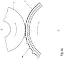
- the teeth 6a, 7a run parallel or obliquely at the angle ⁇ or ⁇ (as shown in Fig. 2) to the respective disc axis.
- the 255 teeth 6a arranged uniformly on the circumference of the upsetting disk 6 run at an angle ⁇ of 40 ° obliquely to the disk axis.
- the second upsetting disk 7 has the same diameter D as the first upsetting disk 6 and the same number Z of teeth 7a.
- the teeth 7a of the second upsetting disk 7 also run obliquely to the disk axis, but their orientation is opposite to the orientation of the teeth 6a of the first upsetting disk 6, so that the impressions of the teeth 6a and 7a cross on the tube (see FIGS. 1 / 4b / 5b).
- heat exchanger tubes can with a highly porous surface structure become.
- an evaporator tube was used such a surface based on integrally rolled Ribs with a thickness of the order of 0.1 mm.
- the channels were successful between the ribs with thin lids emerging from the top Area of the rib were shaped to essentially occlude without the ribs buckling to the side or in itself slumped together.
Landscapes
- Engineering & Computer Science (AREA)
- Physics & Mathematics (AREA)
- Mechanical Engineering (AREA)
- Thermal Sciences (AREA)
- General Engineering & Computer Science (AREA)
- Geometry (AREA)
- Chemical & Material Sciences (AREA)
- Crystallography & Structural Chemistry (AREA)
- Metal Extraction Processes (AREA)
- Forging (AREA)
Applications Claiming Priority (2)
| Application Number | Priority Date | Filing Date | Title |
|---|---|---|---|
| DE19757526 | 1997-12-23 | ||
| DE19757526A DE19757526C1 (de) | 1997-12-23 | 1997-12-23 | Verfahren zur Herstellung eines Wärmeaustauschrohres, insbesondere zur Verdampfung von Flüssigkeiten aus Reinstoffen oder Gemischen auf der Rohraußenseite |
Publications (3)
| Publication Number | Publication Date |
|---|---|
| EP0925856A2 true EP0925856A2 (fr) | 1999-06-30 |
| EP0925856A3 EP0925856A3 (fr) | 2000-04-05 |
| EP0925856B1 EP0925856B1 (fr) | 2002-01-16 |
Family
ID=7853177
Family Applications (1)
| Application Number | Title | Priority Date | Filing Date |
|---|---|---|---|
| EP98122877A Expired - Lifetime EP0925856B1 (fr) | 1997-12-23 | 1998-12-02 | Procédé de fabrication d'un tube d'évaporation |
Country Status (3)
| Country | Link |
|---|---|
| US (1) | US6067832A (fr) |
| EP (1) | EP0925856B1 (fr) |
| DE (2) | DE19757526C1 (fr) |
Cited By (1)
| Publication number | Priority date | Publication date | Assignee | Title |
|---|---|---|---|---|
| CN104117834A (zh) * | 2014-07-11 | 2014-10-29 | 航天海鹰(哈尔滨)钛业有限公司 | 钛或钛合金翅片管的制造方法 |
Families Citing this family (21)
| Publication number | Priority date | Publication date | Assignee | Title |
|---|---|---|---|---|
| DE19963353B4 (de) | 1999-12-28 | 2004-05-27 | Wieland-Werke Ag | Beidseitig strukturiertes Wärmeaustauscherrohr und Verfahren zu dessen Herstellung |
| DE10101589C1 (de) | 2001-01-16 | 2002-08-08 | Wieland Werke Ag | Wärmeaustauscherrohr und Verfahren zu dessen Herstellung |
| DE10159860C2 (de) * | 2001-12-06 | 2003-12-04 | Sdk Technik Gmbh | Wärmeübertragungsfläche mit einer aufgalvanisierten Mikrostruktur von Vorsprüngen |
| US7197808B2 (en) * | 2002-10-28 | 2007-04-03 | Borgwarner Inc. | Process for forming a groove in a friction layer |
| CN100498187C (zh) * | 2007-01-15 | 2009-06-10 | 高克联管件(上海)有限公司 | 一种蒸发冷凝兼备型传热管 |
| CN101338987B (zh) * | 2007-07-06 | 2011-05-04 | 高克联管件(上海)有限公司 | 一种冷凝用传热管 |
| DE102008013929B3 (de) | 2008-03-12 | 2009-04-09 | Wieland-Werke Ag | Verdampferrohr mit optimierten Hinterschneidungen am Nutengrund |
| US9844807B2 (en) * | 2008-04-16 | 2017-12-19 | Wieland-Werke Ag | Tube with fins having wings |
| DE202008005886U1 (de) | 2008-04-29 | 2008-09-04 | Hellwig, Udo, Prof. Dr. | Einrichtung zum Erwärmen eines Fluides |
| DE202008005887U1 (de) | 2008-04-29 | 2008-09-04 | Hellwig, Udo, Prof. Dr. | Behälter zum Aufnehmen und Erwärmen von Fluiden |
| DE202008007183U1 (de) | 2008-05-28 | 2008-10-02 | Hellwig, Udo, Prof. Dr. | Erwärmungseinrichtung |
| DE102011121733A1 (de) | 2011-12-21 | 2013-06-27 | Wieland-Werke Ag | Verdampferrohr mit optimierter Außenstruktur |
| DE102014002829A1 (de) | 2014-02-27 | 2015-08-27 | Wieland-Werke Ag | Metallisches Wärmeaustauscherrohr |
| DE102016006914B4 (de) | 2016-06-01 | 2019-01-24 | Wieland-Werke Ag | Wärmeübertragerrohr |
| US9945618B1 (en) * | 2017-01-04 | 2018-04-17 | Wieland Copper Products, Llc | Heat transfer surface |
| DE102018004701A1 (de) | 2018-06-12 | 2019-12-12 | Wieland-Werke Ag | Metallisches Wärmeaustauscherrohr |
| CN111707122B (zh) * | 2020-05-07 | 2022-03-25 | 华南理工大学 | 一种具有表面混合润湿性的外翅片管及其制备方法 |
| MX2023004837A (es) | 2020-10-31 | 2023-05-10 | Wieland Werke Ag | Tubo intercambiador de calor de metal. |
| WO2022089773A1 (fr) | 2020-10-31 | 2022-05-05 | Wieland-Werke Ag | Tube métallique d'échangeur de chaleur |
| DE202020005625U1 (de) | 2020-10-31 | 2021-11-10 | Wieland-Werke Aktiengesellschaft | Metallisches Wärmeaustauscherrohr |
| DE202020005628U1 (de) | 2020-10-31 | 2021-11-11 | Wieland-Werke Aktiengesellschaft | Metallisches Wärmeaustauscherrohr |
Family Cites Families (12)
| Publication number | Priority date | Publication date | Assignee | Title |
|---|---|---|---|---|
| US1865575A (en) * | 1928-11-30 | 1932-07-05 | Wolverine Tube Company | Apparatus for manufacturing integral finned tubing |
| BE669560A (fr) * | 1964-12-28 | |||
| US3696861A (en) * | 1970-05-18 | 1972-10-10 | Trane Co | Heat transfer surface having a high boiling heat transfer coefficient |
| DE2808080C2 (de) * | 1977-02-25 | 1982-12-30 | Furukawa Metals Co., Ltd., Tokyo | Wärmeübertragungs-Rohr für Siedewärmetauscher und Verfahren zu seiner Herstellung |
| DE2758526C2 (de) * | 1977-12-28 | 1986-03-06 | Wieland-Werke Ag, 7900 Ulm | Verfahren und Vorrichtung zur Herstellung eines Rippenrohres |
| US4577381A (en) * | 1983-04-01 | 1986-03-25 | Kabushiki Kaisha Kobe Seiko Sho | Boiling heat transfer pipes |
| AU4316185A (en) * | 1984-06-18 | 1986-01-02 | Borg-Warner Corporation | Heat transfer tube and manufacture thereof |
| US4660630A (en) * | 1985-06-12 | 1987-04-28 | Wolverine Tube, Inc. | Heat transfer tube having internal ridges, and method of making same |
| US5054548A (en) * | 1990-10-24 | 1991-10-08 | Carrier Corporation | High performance heat transfer surface for high pressure refrigerants |
| DE4420756C1 (de) * | 1994-06-15 | 1995-11-30 | Wieland Werke Ag | Mehrgängiges Rippenrohr und Verfahren zu dessen Herstellung |
| DE69525594T2 (de) * | 1994-11-17 | 2002-08-22 | Carrier Corp., Syracuse | Wärmeaustauschrohr |
| US5697430A (en) * | 1995-04-04 | 1997-12-16 | Wolverine Tube, Inc. | Heat transfer tubes and methods of fabrication thereof |
-
1997
- 1997-12-23 DE DE19757526A patent/DE19757526C1/de not_active Expired - Fee Related
-
1998
- 1998-12-02 DE DE59802629T patent/DE59802629D1/de not_active Expired - Lifetime
- 1998-12-02 EP EP98122877A patent/EP0925856B1/fr not_active Expired - Lifetime
- 1998-12-16 US US09/212,525 patent/US6067832A/en not_active Expired - Lifetime
Cited By (1)
| Publication number | Priority date | Publication date | Assignee | Title |
|---|---|---|---|---|
| CN104117834A (zh) * | 2014-07-11 | 2014-10-29 | 航天海鹰(哈尔滨)钛业有限公司 | 钛或钛合金翅片管的制造方法 |
Also Published As
| Publication number | Publication date |
|---|---|
| EP0925856B1 (fr) | 2002-01-16 |
| DE19757526C1 (de) | 1999-04-29 |
| DE59802629D1 (de) | 2002-02-21 |
| US6067832A (en) | 2000-05-30 |
| EP0925856A3 (fr) | 2000-04-05 |
Similar Documents
| Publication | Publication Date | Title |
|---|---|---|
| EP0925856B1 (fr) | Procédé de fabrication d'un tube d'évaporation | |
| DE4404357C1 (de) | Wärmeaustauschrohr zum Kondensieren von Dampf | |
| EP1223400B1 (fr) | Tube d'échangeur de chaleur et son procédé de fabrication | |
| DE69814904T2 (de) | Rippe für einstückigen wärmetauscher und verfahren zu deren herstellung | |
| DE69215988T2 (de) | Wärmeaustauschrohre und Verfahren zur Herstellung | |
| DE3332282C2 (de) | Wärmetauschrohr | |
| DE69302668T2 (de) | Wärmetauscherrohr | |
| DE60209750T2 (de) | Verbessertes wärmeübertragungsrohr mit genuteter innenfläche | |
| DE19628280C2 (de) | Wärmeübertragungsrohr mit einer gerillten Innenfläche | |
| DE10156374C1 (de) | Beidseitig strukturiertes Wärmeaustauscherrohr und Verfahren zu dessen Herstellung | |
| DE4420756C1 (de) | Mehrgängiges Rippenrohr und Verfahren zu dessen Herstellung | |
| DE102009007446B4 (de) | Wärmeübertragerrohr und Verfahren zu dessen Herstellung | |
| DE19963353B4 (de) | Beidseitig strukturiertes Wärmeaustauscherrohr und Verfahren zu dessen Herstellung | |
| EP1156294B1 (fr) | Tube d'échangeur de chaleur pour évaporation avec des pores de tailles différentes | |
| DE3882181T2 (de) | Verfahren zur Herstellung einer vergrösserten Wärmeübertragungsfläche und Vorrichtung zur Durchführung des Verfahrens. | |
| EP0925128A1 (fr) | Procede et dispositif de fabrication d'une tole metallique ondulee presentant une microstructure dans le sens transversal de l'ondulation | |
| EP2339283A2 (fr) | Tuyau de transfert de chaleur et procédé de fabrication d'un tuyau de transfert de chaleur | |
| DE2303192A1 (de) | Rippenrohr sowie verfahren und vorrichtung zu seiner herstellung | |
| EP3111153B1 (fr) | Tube d'échangeur de chaleur métallique | |
| DE2758527C2 (de) | Verfahren und Vorrichtung zur Herstellung eines Rippenrohres | |
| DE102004049809A1 (de) | Flachrohr für Wärmetauscher | |
| WO2022089773A1 (fr) | Tube métallique d'échangeur de chaleur | |
| EP4237781A1 (fr) | Tube métallique d'échangeur de chaleur | |
| CH626986A5 (en) | Heat exchange tube for a heat exchanger, and method for producing it | |
| DE2335306C3 (de) | Rippenrohr für Wärmetauscher und Verfahren zu seiner Herstellung |
Legal Events
| Date | Code | Title | Description |
|---|---|---|---|
| PUAI | Public reference made under article 153(3) epc to a published international application that has entered the european phase |
Free format text: ORIGINAL CODE: 0009012 |
|
| 17P | Request for examination filed |
Effective date: 19981202 |
|
| AK | Designated contracting states |
Kind code of ref document: A2 Designated state(s): DE FR GB |
|
| AX | Request for extension of the european patent |
Free format text: AL;LT;LV;MK;RO;SI |
|
| PUAL | Search report despatched |
Free format text: ORIGINAL CODE: 0009013 |
|
| AK | Designated contracting states |
Kind code of ref document: A3 Designated state(s): AT BE CH CY DE DK ES FI FR GB GR IE IT LI LU MC NL PT SE |
|
| AX | Request for extension of the european patent |
Free format text: AL;LT;LV;MK;RO;SI |
|
| RIC1 | Information provided on ipc code assigned before grant |
Free format text: 7B 21C 37/20 A, 7F 28F 1/36 B |
|
| AKX | Designation fees paid |
Free format text: DE FR GB |
|
| GRAG | Despatch of communication of intention to grant |
Free format text: ORIGINAL CODE: EPIDOS AGRA |
|
| GRAG | Despatch of communication of intention to grant |
Free format text: ORIGINAL CODE: EPIDOS AGRA |
|
| GRAH | Despatch of communication of intention to grant a patent |
Free format text: ORIGINAL CODE: EPIDOS IGRA |
|
| 17Q | First examination report despatched |
Effective date: 20010427 |
|
| GRAH | Despatch of communication of intention to grant a patent |
Free format text: ORIGINAL CODE: EPIDOS IGRA |
|
| GRAA | (expected) grant |
Free format text: ORIGINAL CODE: 0009210 |
|
| REG | Reference to a national code |
Ref country code: GB Ref legal event code: IF02 |
|
| AK | Designated contracting states |
Kind code of ref document: B1 Designated state(s): DE FR GB |
|
| REF | Corresponds to: |
Ref document number: 59802629 Country of ref document: DE Date of ref document: 20020221 |
|
| GBT | Gb: translation of ep patent filed (gb section 77(6)(a)/1977) |
Effective date: 20020410 |
|
| ET | Fr: translation filed | ||
| PLBE | No opposition filed within time limit |
Free format text: ORIGINAL CODE: 0009261 |
|
| STAA | Information on the status of an ep patent application or granted ep patent |
Free format text: STATUS: NO OPPOSITION FILED WITHIN TIME LIMIT |
|
| 26N | No opposition filed | ||
| REG | Reference to a national code |
Ref country code: FR Ref legal event code: PLFP Year of fee payment: 18 |
|
| PGFP | Annual fee paid to national office [announced via postgrant information from national office to epo] |
Ref country code: GB Payment date: 20151202 Year of fee payment: 18 |
|
| REG | Reference to a national code |
Ref country code: FR Ref legal event code: PLFP Year of fee payment: 19 |
|
| GBPC | Gb: european patent ceased through non-payment of renewal fee |
Effective date: 20161202 |
|
| REG | Reference to a national code |
Ref country code: FR Ref legal event code: PLFP Year of fee payment: 20 |
|
| PG25 | Lapsed in a contracting state [announced via postgrant information from national office to epo] |
Ref country code: GB Free format text: LAPSE BECAUSE OF NON-PAYMENT OF DUE FEES Effective date: 20161202 |
|
| PGFP | Annual fee paid to national office [announced via postgrant information from national office to epo] |
Ref country code: FR Payment date: 20171012 Year of fee payment: 20 |
|
| PGFP | Annual fee paid to national office [announced via postgrant information from national office to epo] |
Ref country code: DE Payment date: 20171231 Year of fee payment: 20 |
|
| REG | Reference to a national code |
Ref country code: DE Ref legal event code: R071 Ref document number: 59802629 Country of ref document: DE |