EP0925858A1 - Procédé et dispositif pour le compactage du sable de moulage - Google Patents
Procédé et dispositif pour le compactage du sable de moulage Download PDFInfo
- Publication number
- EP0925858A1 EP0925858A1 EP98119963A EP98119963A EP0925858A1 EP 0925858 A1 EP0925858 A1 EP 0925858A1 EP 98119963 A EP98119963 A EP 98119963A EP 98119963 A EP98119963 A EP 98119963A EP 0925858 A1 EP0925858 A1 EP 0925858A1
- Authority
- EP
- European Patent Office
- Prior art keywords
- compressed gas
- molding sand
- openings
- compacting
- molding
- Prior art date
- Legal status (The legal status is an assumption and is not a legal conclusion. Google has not performed a legal analysis and makes no representation as to the accuracy of the status listed.)
- Withdrawn
Links
- 238000000465 moulding Methods 0.000 title claims description 26
- 238000000034 method Methods 0.000 title claims description 19
- 239000004576 sand Substances 0.000 title abstract description 3
- 239000003110 molding sand Substances 0.000 claims description 52
- 238000007906 compression Methods 0.000 claims description 18
- 238000003825 pressing Methods 0.000 claims description 17
- 230000006835 compression Effects 0.000 claims description 15
- 238000009423 ventilation Methods 0.000 claims description 5
- 230000007704 transition Effects 0.000 claims description 3
- 238000005056 compaction Methods 0.000 description 3
- 230000002349 favourable effect Effects 0.000 description 2
- 230000009286 beneficial effect Effects 0.000 description 1
- 238000009826 distribution Methods 0.000 description 1
- 230000000694 effects Effects 0.000 description 1
- 239000012530 fluid Substances 0.000 description 1
- 238000004519 manufacturing process Methods 0.000 description 1
- 230000002093 peripheral effect Effects 0.000 description 1
- 238000000926 separation method Methods 0.000 description 1
- 238000013022 venting Methods 0.000 description 1
Images


Classifications
-
- B—PERFORMING OPERATIONS; TRANSPORTING
- B22—CASTING; POWDER METALLURGY
- B22C—FOUNDRY MOULDING
- B22C15/00—Moulding machines characterised by the compacting mechanism; Accessories therefor
- B22C15/28—Compacting by different means acting simultaneously or successively, e.g. preliminary blowing and finally pressing
Definitions
- the invention relates to a method for compressing Molding sand, with one provided with ventilation recesses Model plate a shape model and this with distance molding box placed on the side, molding sand in the Mold box filled and pressure-tight on the mold box compressed gas openings connected to a compressed gas connection and press die having press device adapted to the molding box is set up directly or indirectly. Furthermore, the invention relates to a device for Implementation of such a procedure.
- EP 0 263 977 B1 describes both such a method and also a device for its implementation is known.
- Molding sand which is a molding model placed on a model plate surrounds on the molded box one adapted to this Press device with press rams and pressurized gas openings placed.
- the molding sand is first passed through the pressurized gas openings Compressed gas supplied in a uniform flow whereby the gas passes through all openings of the Press device flows into the molding sand, and then the Molding sand mechanically pressed using the press ram.
- the compression can high and low model sections when compacting subsequent lowering of the model to tear off of the shape bale.
- This task is carried out in a method of the aforementioned Art solved in that individual or groups of over essentially the entire cross-sectional area of the molding box distributed pressure gas openings from the Pressurized gas connection to be pressurized separately and that the compressed gas flowing out of the compressed gas openings the molding sand in the opposing openings Areas compacted.
- this can be done by an introduction of the compressed gas at predetermined, defined Place the molding sand with the desired intensity total volume of molding sand variable in different areas be compressed.
- This is advantageous a locally optimal even with complicated shape models To achieve compaction.
- the respective requirements the hardness of the mold to be produced can vary accordingly Areas freely chosen within wide limits become. A clean separation of the mold model from the molding sand is thus ensured and bale breaks become reliable prevented.
- a particularly homogeneous compression curve is according to one advantageous development of the invention achieved, if consecutively individual or groups of compressed gas openings be pressurized with gas. This allows the The increase in pressure in the molding sand volume is very different become.
- the control of the compressed gas openings is advantageous particularly easy if the compressed gas openings by actuating valve pistons from in the opening area or arranged in a feed line to the compressed gas openings Opening valves are pressurized with compressed gas. This guarantees high variability and freedom of movement inventive method, if preferably individual or Groups of compressed gas openings with different compressed gas Pressurized and / or different volume flow become.
- the press rams are identical executed and are controlled in the same way, so that they exert even pressure on the molding sand volume.
- the differentiated pressurized gas supply caused different compression however, it is in different areas of molding sand volume of particular advantage if individual or groups of Press stamp generate a different pressing pressure.
- a device for performing the method of the above-mentioned task thereby solved that the pressurized gas openings over essentially distributed the entire cross-sectional area of the molding box are arranged and that the compressed gas outlet at least some of the compressed gas openings can be controlled separately.
- a device is an individual compression in different areas of the in the molding box arranged molding sand volume advantageously allows.
- the device is special can be used flexibly if preferably every compressed gas opening an opening valve in its opening area or in the supply line having.
- valve pistons in a transition area between a piston side wall and one of the valve outlet side facing piston crown each have a bevelled ring surface on
- the valves can be particularly easily pushed through an application of the interior of the valve piston with a Gas of lower pressure than that of the Pressurized gas connection (in a particularly simple manner, this can be a arranged around the opening valves or parts thereof Pressurized gas space) is made available, operate. That on the bevelled ring surface on the outside of the piston In this case, the pressure gas acting ensures a simple one and quick opening of the respective valve. Consequently guides the bevelled ring surface of the outer edge of the valve piston crown when pressurized with compressed gas at the same time Vent the interior of the valve piston to one Opening the valve.
- the flow of the flowing out of the compressed gas openings Compressed gas is particularly balanced and even when the bottom surface of the valve pistons facing the valve outlet side arranged symmetrically to the center of the piston Area is concave and curved away from the piston crown.
- the ram can be operated independently and can be used in such a way that the predetermined and targeted compression of the molding sand volume reinforce.
- Figure 1 is a device for compacting molding sand in a sectional side view (along line I-I in Figure 3) shown.
- the device has a model plate 3 with a shape model 4 placed thereon, that of one also placed on the model plate 3 Mold box 6 arranged molding sand 5 is surrounded. In its edge areas, the model plate 4 has ventilation openings 2 provided.
- a chamber 22 with a pressing device 1 rests on one Filling frame 21 which is arranged on the molding box 6.
- the filling frame 21 with Molding sand 5 may be provided.
- the chamber 22 is pressure-tight the filling frame 21 put on, which is also pressure-tight with the molding box 6 and the model plate 3 is connected.
- the chamber 22 is at her the pressing device 1 and Mold box 6 facing end with a pressurized gas, for. B. Compressed air, filled compressed gas chamber 18 connected. Of the Pressurized gas chamber 18 is directly on the pressing device 1 connected in which a plurality of compressed gas supply lines 9 with compressed gas openings 7 and press units 23 (see Figure 2) arranged with ram 8 and ram 19 is.
- the compressed gas feed lines 9 are directly from the Pressurized gas space 18, wherein in the region of the bottom of the Compressed gas chamber 18 arranged opening valves 10 with valve pistons 11, the control lines 17 of control units 16 pneumatically operated, the compressed gas outlet steer out of the openings 7.
- the valve pistons 11 are included can be operated independently of each other.
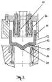
- valve piston 11 is cup-shaped and a side wall 12 and has a bottom 15.
- the transition from the side wall 12 to the bottom 15 forms a bevelled ring surface 13.
- the bottom surface facing the valve outlet side 14 is arranged symmetrically to the center of the piston Area 25 concave and arched away from the floor 15.
- FIG 3 which is a sectional view from above along Line III-III in Figure 2 of the device for compressing Shaped sand shows the arrangement and distribution of the compressed gas openings 7 and pressing units 23 over the cross-sectional area of the molding box 6.
- a square Arrangement are thirty-six press units 23 over the entire cross-sectional area of the chamber 22 and thus also the molding box 6 distributed. Between the press units 23 and also over the entire cross-sectional area of the molding box 6 are arranged twenty-four compressed gas openings 7.
- Figure 2 shows in a section along line II-II of the figure 3 the structure of the press units 23.
- the press ram 8 is carried out using pressure oil or a other hydraulic fluid, each via one Pressure oil port 20 is supplied.
- the pressure oil connections 20 are from a hydraulic system not shown here fed.
- the pressing device 1 is advantageously arranged such that it can be displaced in height, so that they can be placed on the filling frame 21 or after the compression process of the filling frame 21 again is removable.
- the valve piston 11 of the Valves 10 opened in that with the help of the control units 16 and the control lines 17 in a piston interior 26 ( Figure 4) a pressure is generated which is lower than the pressure prevailing in the compressed gas space 18.
- On the tapered annular surface 13 of the valve piston 11 acting Compressed gas causes the valves to open quickly 10.
- each valve 10 with a control line 17 a control unit 16 is connected - if the Control units 16 can be actuated independently of one another only pressurized gas openings 7 are pressurized, that compact the molding sand 5 in predetermined areas. It is Z. B. conceivable that with the help of a program control Position, time, duration and sequence of the pressurization the compressed gas openings 7 predetermined and so the compression process is set. This is a goal Compression enables. It is also conceivable for the valves 10 to be equipped with different opening strokes. Then if z. B. opening the valves with the valves the smallest opening stroke begins and continues valves with a larger opening stroke results a pressure rise curve that is initially flat and then increases with increasing pressure Incline runs.
- the compressed gas emerging from the openings 7 compresses the Molding sand 5 and escapes through the ventilation recesses 2 the model plate 3 from the device.
Landscapes
- Engineering & Computer Science (AREA)
- Mechanical Engineering (AREA)
- Casting Devices For Molds (AREA)
Applications Claiming Priority (2)
| Application Number | Priority Date | Filing Date | Title |
|---|---|---|---|
| DE19755755 | 1997-12-16 | ||
| DE1997155755 DE19755755A1 (de) | 1997-12-16 | 1997-12-16 | Verfahren und Vorrichtung zum Verdichten von Formsand |
Publications (1)
| Publication Number | Publication Date |
|---|---|
| EP0925858A1 true EP0925858A1 (fr) | 1999-06-30 |
Family
ID=7852008
Family Applications (1)
| Application Number | Title | Priority Date | Filing Date |
|---|---|---|---|
| EP98119963A Withdrawn EP0925858A1 (fr) | 1997-12-16 | 1998-10-22 | Procédé et dispositif pour le compactage du sable de moulage |
Country Status (2)
| Country | Link |
|---|---|
| EP (1) | EP0925858A1 (fr) |
| DE (1) | DE19755755A1 (fr) |
Citations (3)
| Publication number | Priority date | Publication date | Assignee | Title |
|---|---|---|---|---|
| EP0263977A2 (fr) * | 1986-10-11 | 1988-04-20 | Heinrich Wagner Sinto Maschinenfabrik GmbH | Dispositif pour le compactage du sable de moulage |
| DE4407524A1 (de) * | 1994-03-07 | 1995-09-14 | Georg Grabsch | Fallstromverdichten von Sandformen |
| EP0802004A2 (fr) * | 1996-04-19 | 1997-10-22 | Sintokogio, Ltd. | Procédé de remplissage des noyaux avec du sable de moulage |
Family Cites Families (2)
| Publication number | Priority date | Publication date | Assignee | Title |
|---|---|---|---|---|
| CH671715A5 (en) * | 1986-06-13 | 1989-09-29 | Fischer Ag Georg | Compacting casting moulds |
| DE3701438A1 (de) * | 1987-01-20 | 1988-07-28 | Josef Mertes Engineering Fuer | Verfahren und vorrichtung zum verdichten von kornfoermigen formstoffen z.b. giessereiformsand |
-
1997
- 1997-12-16 DE DE1997155755 patent/DE19755755A1/de not_active Ceased
-
1998
- 1998-10-22 EP EP98119963A patent/EP0925858A1/fr not_active Withdrawn
Patent Citations (3)
| Publication number | Priority date | Publication date | Assignee | Title |
|---|---|---|---|---|
| EP0263977A2 (fr) * | 1986-10-11 | 1988-04-20 | Heinrich Wagner Sinto Maschinenfabrik GmbH | Dispositif pour le compactage du sable de moulage |
| DE4407524A1 (de) * | 1994-03-07 | 1995-09-14 | Georg Grabsch | Fallstromverdichten von Sandformen |
| EP0802004A2 (fr) * | 1996-04-19 | 1997-10-22 | Sintokogio, Ltd. | Procédé de remplissage des noyaux avec du sable de moulage |
Also Published As
| Publication number | Publication date |
|---|---|
| DE19755755A1 (de) | 1999-06-24 |
Similar Documents
| Publication | Publication Date | Title |
|---|---|---|
| DE69817480T2 (de) | Verfahren zum pressen von keramischen pulvern und vorrichtung zum durchführen des verfahrens | |
| DE3036533A1 (de) | Presse zur herstellung von formkoerpern aus pulver | |
| DE69811789T2 (de) | Verfahren zum Herstellen von keramischen Fliesen, einschliesslich Fliesen mit grossen Abmessungen, durch ein teilweise isostatisches Pressen und Vorrichtung zum durchführen des Verfahrens | |
| DE1577221C3 (de) | Presse zum Verpressen von pulverförmigem Material | |
| DE69817482T2 (de) | Verfahren zum herstellen von keramischen fliesen , einschliesslich fliesen mit grossen abmessungen und vorrichtung zum durchführen des verfahrens | |
| DE102013216863B4 (de) | Werkzeugsystem und Verfahren zur Herstellung von Bauteilen nach dem RTM-Verfahren | |
| EP0263977B1 (fr) | Dispositif pour le compactage du sable de moulage | |
| DE2406688A1 (de) | Vorrichtung zum verdichten von formfuellungen, insbesondere betonfuellungen fuer betonsteinformen | |
| DE2933869C2 (de) | Verfahren und Vorrichtung zum Herstellen eines unteren Formteils | |
| DE19540189A1 (de) | Preßvorrichtung und -verfahren zur Herstellung von Formteilen aus Faserverbundwerkstoffen | |
| DE1941736B1 (de) | Verfahren bei kastenlosen Formmaschinen zum Einschiessen des Formsandes und Maschine zur Durchfuehrung desselben | |
| EP0650788A1 (fr) | Dispositif de compactage de matériaux pulvérulents | |
| DE19755755A1 (de) | Verfahren und Vorrichtung zum Verdichten von Formsand | |
| DE2727297B2 (de) | Verfahren und Einrichtung zum Herstellen von Gießereisandformen | |
| DE610379C (de) | Ruettelformmaschine | |
| DE102005027296B3 (de) | Vorrichtung zum Herstellen eines Formteils aus Pulver | |
| EP0131723B1 (fr) | Dispositif pour le serrage de matière de moulage de fonderie à l'aide de gaz comprimé | |
| DE3914160C1 (fr) | ||
| DE3025993C2 (de) | Formvorrichtung zur Explosionsverdichtung eines sandartigen Füllmaterials | |
| DE859121C (de) | Verfahren und Vorrichtung zur Herstellung von Ton-Hohlziegeln | |
| DE69405303T2 (de) | Modulare hydraulische Presse zur Herstellung von keramischen Gegenständen | |
| DE2420428C3 (de) | Anlage zum isostatischen Pressen von keramischen Erzeugnissen aus pulverförmigen Massen | |
| DE2802331A1 (de) | Vorrichtung zur steuerung des zu- und abflusses von oel in einer presse und zur unterdrucksetzung des hydraulikantriebes | |
| CH659411A5 (de) | Formmaschine und verwendung derselben. | |
| EP0327826B1 (fr) | Dispositif pour le serrage de sable de moulage |
Legal Events
| Date | Code | Title | Description |
|---|---|---|---|
| PUAI | Public reference made under article 153(3) epc to a published international application that has entered the european phase |
Free format text: ORIGINAL CODE: 0009012 |
|
| AK | Designated contracting states |
Kind code of ref document: A1 Designated state(s): AT CH DE ES FR GB IT LI NL SE |
|
| AX | Request for extension of the european patent |
Free format text: AL;LT;LV;MK;RO;SI |
|
| 17P | Request for examination filed |
Effective date: 19990531 |
|
| AKX | Designation fees paid |
Free format text: AT CH DE ES FR GB IT LI NL SE |
|
| 17Q | First examination report despatched |
Effective date: 20020521 |
|
| STAA | Information on the status of an ep patent application or granted ep patent |
Free format text: STATUS: THE APPLICATION IS DEEMED TO BE WITHDRAWN |
|
| 18D | Application deemed to be withdrawn |
Effective date: 20021001 |