EP0925871B1 - Dispositif de serrage - Google Patents
Dispositif de serrage Download PDFInfo
- Publication number
- EP0925871B1 EP0925871B1 EP98204002A EP98204002A EP0925871B1 EP 0925871 B1 EP0925871 B1 EP 0925871B1 EP 98204002 A EP98204002 A EP 98204002A EP 98204002 A EP98204002 A EP 98204002A EP 0925871 B1 EP0925871 B1 EP 0925871B1
- Authority
- EP
- European Patent Office
- Prior art keywords
- pull rod
- engaging member
- clamping apparatus
- engaging
- housing
- Prior art date
- Legal status (The legal status is an assumption and is not a legal conclusion. Google has not performed a legal analysis and makes no representation as to the accuracy of the status listed.)
- Expired - Lifetime
Links
Images


Classifications
-
- B—PERFORMING OPERATIONS; TRANSPORTING
- B25—HAND TOOLS; PORTABLE POWER-DRIVEN TOOLS; MANIPULATORS
- B25B—TOOLS OR BENCH DEVICES NOT OTHERWISE PROVIDED FOR, FOR FASTENING, CONNECTING, DISENGAGING OR HOLDING
- B25B5/00—Clamps
- B25B5/06—Arrangements for positively actuating jaws
- B25B5/061—Arrangements for positively actuating jaws with fluid drive
-
- B—PERFORMING OPERATIONS; TRANSPORTING
- B23—MACHINE TOOLS; METAL-WORKING NOT OTHERWISE PROVIDED FOR
- B23B—TURNING; BORING
- B23B31/00—Chucks; Expansion mandrels; Adaptations thereof for remote control
- B23B31/02—Chucks
- B23B31/10—Chucks characterised by the retaining or gripping devices or their immediate operating means
- B23B31/12—Chucks with simultaneously-acting jaws, whether or not also individually adjustable
- B23B31/20—Longitudinally-split sleeves, e.g. collet chucks
- B23B31/201—Characterized by features relating primarily to remote control of the gripping means
- B23B31/202—Details of the jaws
-
- B—PERFORMING OPERATIONS; TRANSPORTING
- B23—MACHINE TOOLS; METAL-WORKING NOT OTHERWISE PROVIDED FOR
- B23Q—DETAILS, COMPONENTS, OR ACCESSORIES FOR MACHINE TOOLS, e.g. ARRANGEMENTS FOR COPYING OR CONTROLLING; MACHINE TOOLS IN GENERAL CHARACTERISED BY THE CONSTRUCTION OF PARTICULAR DETAILS OR COMPONENTS; COMBINATIONS OR ASSOCIATIONS OF METAL-WORKING MACHINES, NOT DIRECTED TO A PARTICULAR RESULT
- B23Q1/00—Members which are comprised in the general build-up of a form of machine, particularly relatively large fixed members
- B23Q1/0063—Connecting non-slidable parts of machine tools to each other
- B23Q1/0081—Connecting non-slidable parts of machine tools to each other using an expanding clamping member insertable in a receiving hole
- B23Q1/009—Connecting non-slidable parts of machine tools to each other using an expanding clamping member insertable in a receiving hole the receiving hole being cylindrical or conical
-
- B—PERFORMING OPERATIONS; TRANSPORTING
- B25—HAND TOOLS; PORTABLE POWER-DRIVEN TOOLS; MANIPULATORS
- B25B—TOOLS OR BENCH DEVICES NOT OTHERWISE PROVIDED FOR, FOR FASTENING, CONNECTING, DISENGAGING OR HOLDING
- B25B5/00—Clamps
- B25B5/06—Arrangements for positively actuating jaws
- B25B5/08—Arrangements for positively actuating jaws using cams
- B25B5/087—Arrangements for positively actuating jaws using cams actuated by a hydraulic or pneumatic piston
-
- B—PERFORMING OPERATIONS; TRANSPORTING
- B25—HAND TOOLS; PORTABLE POWER-DRIVEN TOOLS; MANIPULATORS
- B25B—TOOLS OR BENCH DEVICES NOT OTHERWISE PROVIDED FOR, FOR FASTENING, CONNECTING, DISENGAGING OR HOLDING
- B25B5/00—Clamps
- B25B5/14—Clamps for work of special profile
- B25B5/147—Clamps for work of special profile for pipes
-
- B—PERFORMING OPERATIONS; TRANSPORTING
- B23—MACHINE TOOLS; METAL-WORKING NOT OTHERWISE PROVIDED FOR
- B23B—TURNING; BORING
- B23B2231/00—Details of chucks, toolholder shanks or tool shanks
- B23B2231/20—Collet chucks
- B23B2231/2027—Gripping surfaces, i.e. the surface contacting the tool or workpiece
- B23B2231/204—Gripping surfaces, i.e. the surface contacting the tool or workpiece with saw tooth profiles
Definitions
- the present invention relates to a clamping apparatus of such a type that pulls a workpiece, a metal mold or the like object to be fixed, to a work pallet, a table or the like support pedestal and fixes it thereto.
- a common clamping apparatus is adapted to arrange a clamping member around an object to be fixed which has been placed on a support pedestal and make the clamping member push the object to the support pedestal.
- the conventional clamping apparatus arranged the clamping member around the object to be fixed. Accordingly, there was a disadvantage that the clamping member reduced a working space around the object to be fixed.
- the invention is specified in claim 1, which is chatacterised with respect to EP-0785049-A .
- the present invention aims at proposing a clamping apparatus for improving the disadvantage.
- the present invention has constructed a clamping apparatus in the following manner, for example, as shown in Fig. 1 to Fig. 4 , Fig. 5 to Fig. 8 or Fig. 9 to Fig. 13 , respectively.
- the clamping apparatus comprises a driving means 15 provided within a housing 11, a pull rod 12 to be reciprocally moved in an axial direction by the driving means 15, a tapered outer peripheral surface 12a provided on the pull rod 12 so as to narrow toward a base end (first end) of the axial direction, an engaging member 14 arranged in an outer peripheral space around the tapered outer peripheral surface 12a so as to be inserted into an engaging hole 2 of an object 1 to be fixed, and a support means 29 inhibiting the engaging member 14 from displacing to the base end with a predetermined supporting force and allowing it to displace to the base end with a force larger than the supporting force.
- the pull rod 12 when driven toward the base end, makes the tapered outer peripheral surface 12a change over the engaging member 14 to a radially outward engaging position (X) so as to engage it with the engaging hole 2 and displaces the engaging member 14 to the base end against the support means 29.
- This adapts a driving force of the pull rod 12 to be transmissible to the object 1 to be fixed.
- the pull rod 12 when driven toward a leading end (second end), the pull rod 12 allows the engaging member 14 to change over to a radially inward disengaging position (Y).
- tapered outer peripheral surface 12a is preferably formed to be circular when seen in cross section for the purpose of machining, it may be in a rectangular or the like polygonal shape when seen in cross section.
- the engaging hole 2 of the object 1 to be fixed also preferably has a circular shape for the purpose of machining but it may have a rectangular or the like polygonal shape, when seen in cross section. In the case where the engaging hole 2 is made polygonal, it suffices if a plurality of engaging members 14 are arranged so that they can oppose to the respective sides of the polygonal engaging hole 2.
- the present invention functions in the following manner, for example, as shown in Figs. 1(A) and 2 .
- the driving means 15 (here a piston 17) moves the pull rod 12 upward and the engaging member 14 is supported from below by the support means 29 (here the urging force of the push spring 27).
- the tapered outer peripheral surface 12a of the pull rod 12 projects the engaging member 14 to the radially outward engaging position (X) to thereby engage it with the engaging hole 2.
- the engaging member 14 descends by a stroke (M) against a supporting force of the support means 29 with a downward driving force of the pull rod 12.
- the downward driving force of the pull rod 12 is transmitted to the object 1 to be fixed through the engaging member 14 and the object 1 is pulled toward the housing 11.
- the present invention produces the following effects.
- the object 1 to be fixed can open five of its six surfaces except a surface (R) to be fixed. Therefore, in the case where the object to be fixed is a workpiece, it can have the five surfaces continuously machined while being clamped to result in surprisingly enhancing the efficiency of machining. Further, in the event that the object to be fixed is a metal mold, a space around the metal mold is not reduced. This makes it possible to mount a metal mold of large size and besides improve the workability when exchanging the metal mold.
- the object to be fixed can fulfil the intended purpose if it is provided with an engaging hole. It need not project an attachment for clamping. Thus the object is easily handled.
- the engaging hole When the engaging hole is adapted to be circular in cross section, it can be easily formed by a drill, a reamer or the like. Therefore, the object to be fixed can be machined for providing the engaging hole with a good efficiency.
- FIG. 1 A first embodiment of the present invention is explained with reference to Figs. 1 to 4 .
- numeral 1 designates a workpiece (an object to be fixed) ready to be machined by a machining center.
- the workpiece 1 has six surfaces of a front, a rear, an upper, a lower, a right and a left ones.
- the upper one of the six surfaces is preliminarily provided with a reference surface (a surface to be fixed) (R) by machining.
- the reference surface (R) is formed with a plurality of circular engaging holes 2 and a plurality of guide holes 3 (only two of each of them are shown here).
- numeral 4 indicates a work pallet for supporting the workpiece 1.
- the work pallet 4 has a plurality of clamping apparatuses 5 and a plurality of guide pins 6 (here only two of each of them are shown) fixed thereto.
- An upper surface of a housing 11 of every clamping apparatus 5 forms a support surface (S) for receiving the workpiece 1.
- each of the clamping apparatuses 5 is clamp driven by a below-mentioned driving means 15 (see Figs. 1 (A) and 2 ). Then, as shown in Fig. 2 , the collet 13 diametrically expands to engage with the engaging hole 2 and the workpiece 1 is pulled downwards through the pull rod 12 and the collet 13 to thereby be fixed to the support surfaces (S),(S).
- the pallet 4 is conveyed into a machining center and then the workpiece 1 has five of its six surfaces except the reference surface (R) continuously machined by the machining center.
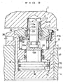
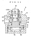
- Figs. 1(A) and 1(B) and Fig. 2 explain a detailed construction of the clamping apparatus 5.
- Fig. 1(A) is a vertical sectional view showing an unclamping condition
- Fig. 1(B) is a sectional view when seen along a line 1B-1B in a direction indicated by arrows in Fig. 1(A) .
- Fig. 2 illustrates a clamping condition.
- the driving means 15 comprises a hydraulic cylinder of double acting type. More specifically, the housing 11 comprises a main body 11a having a cylinder bore 16, into which a clamping piston 17 is inserted.
- the piston 17 has a lower side on which an unclamping actuation chamber 18 is formed and an upper side on which a clamping actuation chamber 19 is provided.
- a piston rod 20 projects upward from the piston 17.
- the housing main body 11a has an upper portion detachably provided with an adapter block 22 for receiving the workpiece 1.
- An upper end surface of the block 22 forms the support surface (S).
- Numeral 23 indicates a fastening bolt (here only one is shown).
- the pull rod 12 is inserted into the adapter block 22 so as to be vertically movable.
- the pull rod 12 has an upper portion provided with a tapered outer peripheral surface 12a circular in section and narrowing downwardly, and it has an input portion 12b connected to an output portion 20a of the piston rod 20 so as to be radially movable and axially unmovable.
- the above-mentioned annular collet (annular member) 13 is externally fitted onto the pull rod 12 vertically movably.
- the collet 13 has a peripheral wall provided with a slit 25 extending vertically.
- An upper half portion of the peripheral wall forms an engaging member 14.
- the engaging member 14 has a tapered inner peripheral surface 14a externally fitted onto the tapered outer peripheral surface 12a of the pull rod 12.
- the engaging member 14 has an outer peripheral surface provided with a plurality of peripheral grooves shaping a saw-tooth when seen in section.
- the collet 13 is pushed up by a push spring 27 and an annular plate 28. These push spring 27 and annular plate 28 compose a support means 29.
- a first annular gap 31 is defined between an outer peripheral surface at a mid-height portion of the collet 13 and an upper end portion of the adapter block 22.
- a second annular gap 32 is formed between an outer peripheral surface of a sleeve 33 externally fitted onto a lower half portion of the collet 13 and the block 22.
- the clamping apparatus 5 operates as follows.
- pressurized oil of the clamping actuation chamber 19 has been discharged through a clamping port 37 and been supplied to the unclamping actuation chamber 18 through an unclamping port 38.
- the pull rod 12 has advanced to its upper limit position by the piston rod 20 and at the same time the collet 13 has advanced to its upper limit position by the push spring 27.
- the engaging member 14 has been changed over to a disengaging position (Y).
- the workpiece 1 can be positioned with respect to the housing 11 with a good accuracy.
- the pressurized oil is discharged from the unclamping actuation chamber 18 and is supplied to the clamping actuation chamber 19, thereby enabling an oil pressure force acting on the piston 17 to lower the pull rod 12.
- the engaging member 14 of the collet 13 diametrically expands by the tapered outer peripheral surface 12a to be changed over to an engaging position (X).
- the thus changed over engaging member 14 engages with the engaging hole 2 of the workpiece 1.
- the pull rod 12 when driven downwards, makes the tapered outer peripheral surface 12a change over the engaging member 14 to the engaging position (X) far away from an axis of the pull rod 12.
- the engaging member 14 engages with the engaging hole 2 in such a state that a saw-tooth portion on the outer peripheral surface of the engaging member 14 causes a peripheral wall of the engaging hole 2 to make a plastic deformation and the saw-tooth portion bites into the thus deformed peripheral wall.
- the collet 13 slightly descends by a stroke (M) against the push spring 27 with a downward driving force of the pull rod 12.
- the downward driving force of the pull rod 12 is transmitted to the workpiece 1 through the engaging member 14 and as a result the workpiece 1 is fixed to the housing 11.
- the cleaning compressed air is inhibited from leaking out to result in increasing pressure at the supply port 40. Therefore, it is possible to judge whether or not the clamping apparatus 5 is in the clamping condition, by detecting the pressure increase through a pressure switch (not shown).
- the pressurized oil is discharged from the clamping actuation chamber 19 and is supplied to the unclamping actuation chamber 18, thereby raising the pull rod 12 relatively to the engaging member 14 engaged with the engaging hole 2. Then, as shown in Fig. 1(A) , the engaging member 14 diametrically contracts by its own resilient force to be changed over to the disengaging position (Y) and thereby cancels the engagement.
- the pull rod 12 when driven upwards, allows the engaging member 14 to change over to the disengaging position (Y) close to the axis. Thereafter, when the workpiece 1 is moved upward, it is smoothly extracted from the engaging member 14.
- the support surface (S) of every housing 11 is cut to the same level prior to using it.
- the adapter block 22 has an upper end surface provided with a working allowance ( ⁇ ) of a predetermined dimension.
- the working allowance ( ⁇ ) is cut through the following procedures.
- the block 22 is removed from the housing main body 11a.
- the push spring 27 has its urging force received by a retaining ring 42 through the annular plate 28.
- the sleeve 33 (see Fig. 1(A) ) is extracted upwardly.
- the pull rod 12 and the collet 13 are moved along a cut-out portion 28a of the annular plate 28 to the right and then extracted upwardly.
- the block 22 is attached to the housing main body 11a again and then the working allowance ( ⁇ ) is cut.
- the block 22 is removed from the housing main body 11a. Then the pull rod 12, the collet 13 and the sleeve 33 (see Fig. 1(A) ) are incorporated into the housing 11 through the procedures substantially opposite to the above-mentioned ones.
- the annular collet 13 is externally fitted onto the pull rod 12 so as to be axially movable and the peripheral wall of the collet 13 is provided with the engaging member 14. Therefore, the engaging member 14 can be reliably supported by a simple structure. Besides, since the peripheral wall of the collet 13 composes the engaging member 14, the collet 13 can change over the engaging member 14 from the engaging position (X) to the disengaging position (Y) with its own resilient force and therefore the change-over can be effected by a simple means.
- the support means 29 is adapted to comprise the push spring 27 and accordingly can be made simple and compact.
- the clamping apparatus 5 can be used over a prolonged period of time. Besides, the pull rod 12 and the collet 13 can be easily removed by detaching the block 22, so that it does not take much labor to conduct the maintenance work for the pull rod 12 and the collet 13.
- the tapered outer peripheral surface 12a of the pull rod 12 is preferable if it has a gradient within a range of about 2 degrees to about 15 degrees.
- a more preferable gradient is within a range of about 2 degrees to about 10 degrees and the most preferable one is within a range of about 4 degrees to about 6 degrees.
- the tapered outer peripheral surface 12a is preferable if it has a cone angle within a range of about 4 degrees to about 30 degrees.
- a more preferable cone angle is within a range of about 4 degrees to about 20 degrees and the most preferable one is within a range of about 8 degrees to about 12 degrees.
- a working fluid for the driving means 15 of fluid pressure type may be other kinds of liquid or gas such as compressed air instead of the pressurized oil.
- the cleaning fluid may be other kinds of gas such as nitrogen gas or liquid instead of the compressed air.
- Fig. 5 to Fig. 8 show another embodiment
- Fig. 9 to Fig. 13 illustrate other different embodiments, respectively.
- the same characters are put to the members having the same structures as those of the first embodiment.
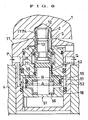
- Fig. 5 to Fig. 8 show a second embodiment.
- This second embodiment arranges a lift member 51 of piston type vertically movably within the housing 11, as shown in Fig. 5 .
- the lift member 51 is provided with the driving means 15 and the pull rod 12.
- the lift member 51 comprises a main piston 51a having an upper side provided with a lowering actuation chamber 52.
- This chamber 52 is communicated with the unclamping actuation chamber 18.
- the main piston 51a has a lower side provided with a raising actuation chamber 53.
- This chamber 53 is communicated with the clamping actuation chamber 19.
- pressurized oil is discharged through a first port (P) and is supplied to the lowering actuation chamber 52 through a second port (Q), thereby lowering the lift member 51 to its lower limit position to retreat the pull rod 12 and the collet 13 downwards of the support surface (S) of the housing 11.
- the support surface (S) can be cut by a predetermined working allowance as well as in the first embodiment.
- cleaning compressed air is discharged through the annular gap 31 defined between the collet 13 and an upper portion of the housing 11.
- the engaging member 14 of the collet 13 has an outer peripheral surface provided with triangular peripheral grooves.
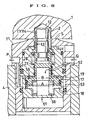
- the piston 17 within the lift member 51 is raised by an oil pressure force of the unclamping actuation chamber 18.
- the piston 17 has an upper surface provided with an annular closing projection 55, which is brought into closing contact with an upper wall of the clamping actuation chamber 19.
- the workpiece 1 When clamping, the workpiece 1 is placed on the support surface (S) of the housing 11. Thereafter, the pressurized oil is discharged from the lowering actuation chamber 52 and is supplied to the raising actuation chamber 53.
- a pressure force acts on an upper surface of the piston 17 only in an annular small area, which is a difference obtained by subtracting a sectional area corresponding to a diameter (B) of the closing projection 55 from a sectional area corresponding to a diameter (A) of the piston 17. Accordingly, in a state where the raising actuation chamber 53 (and the clamping actuation chamber 19 communicated therewith) each have a pressure lower than a predetermined one, the back-up spring 56 has an urging force larger than a hydraulic lowering force acting on the piston 17 and therefore the piston 17 is held in a raised state.
- the piston 17 is provided with the closing projection 55. Accordingly, the back-up spring 56 for holding the piston 17 at the raised position can fulfil the intended purpose only if it has a small urging force. This results in decreasing a reduction of the clamping force and besides making the housing 11 compact.
- the pressurized oil is discharged from the raising actuation chamber 53 and is supplied to the lowering actuation chamber 52.
- the lift member 51 is inhibited from descending by the engaging member 14 which is being engaged with the engaging hole 2. Therefore, the unclamping actuation chamber 18 raises the piston 17 with its oil pressure force, thereby moving the pull rod 12 upward relatively to the engaging member 14 which is being engaged as mentioned above. Subsequently, as shown in Fig. 8 , the engaging member 14 returns to the disengaging position (Y) with its own resilient force.
- the lowering actuation chamber 52 lowers the lift member 51 with its oil pressure force to thereby return the clamping apparatus 5 to the retreated condition of Fig. 5 .
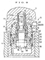
- Fig. 9 shows a third embodiment and correspond to Fig. 6 of the above-mentioned second embodiment.
- Fig. 9 illustrates an apparatus different from the apparatus of Fig. 6 in that a push-up piston 60 is provided instead of the push spring 27 and the annular plate 28 shown in Fig. 6 and that the push-up piston 60 composes the support means 29 with a push-up chamber 61.
- Fig. 9 pressurized oil of lower pressure supplied to the raising actuation chamber 53 through the first port (P) has moved the lift member 51 upward and the collet 13 has the engaging member 14 inserted into the engaging hole 2 of the workpiece 1.
- the clamping piston 17 has the closing projection 55 separated from the upper wall of the clamping actuation chamber 19. Then the pressurized oil within the clamping actuation chamber 19 flows into the push-up chamber 61 to hold the push-up piston 60 at a raised position and the raised push-up piston 60 supports the collet 13 with a predetermined force.
- the clamping actuation chamber 19 drives the clamping piston 17 downward with its oil pressure force, thereby driving the pull rod 12 downward relatively to the raised collet 13.
- the collet 13 has the engaging member 14 engaged with the engaging hole 2 and at the same time the pull rod 12 moves the collet 13 slightly downward with its downward driving force against the upward supporting force of the push-up piston 60. This makes it possible to transmit the downward driving force of the pull rod 12 to the workpiece 1 through the engaging member 14.
- Fig. 10 illustrates a fourth embodiment and corresponds to Fig. 6 . It shows both of the first and second ports (P) and (Q) supplied with no pressurized oil.
- a value of a downward oil pressure force acting on an annular sectional area obtained by subtracting a sectional area corresponding to the D 3 from a sectional area corresponding to the D 1 is set to become larger than a total value of an upward oil pressure force acting on a sectional area corresponding to the D 2 and the upward urging force (F) of the spring 56.
- the lift member 51 ascends with an oil pressure force acting on an annular sectional area obtained by subtracting a sectional area corresponding to the D 4 from the sectional area corresponding to the D 1 and with the urging force (F) of the spring 56.
- the clamping piston 17 descends against the spring 56 with an oil pressure force acting on an annular sectional area obtained by subtracting the sectional area corresponding to the D 4 from the sectional area corresponding to the D 2 .
- the piston 17 drives the pull rod 12 downward.
- Fig. 11 illustrates a fifth embodiment and corresponds to Fig. 1 .
- This Fig. 11 shows an apparatus simplifying the apparatus of Fig. 1 and differs therefrom on the following point.
- the driving means 15 comprises a hydraulic cylinder of single acting and spring return type.
- the piston 17 has an upper side provided with the clamping actuation chamber 19 and a lower side to which a return spring 65 is attached.
- the support means 29 for the collet 13 is composed only of the push spring 27.
- the collet 13 has a peripheral wall provided with a plurality of slits 25 opening toward its upper surface and its lower surface and arranged alternately in a peripheral direction.
- the pull rod 12 is adapted to be horizontally movable while aligning, relatively to the piston rod 20.
- the pull rod 12 and the collet 13 are also adapted to be horizontally movable while aligning, relatively to the housing 11.
- the driving means 15 of cylinder type may be formed into a double acting type similar to that of Fig. 1 .
- Fig. 12 illustrates a sixth embodiment and corresponds to Fig. 11 .
- Fig. 12 shows an apparatus different from the apparatus of Fig. 11 in that the annular member 13 corresponding to the collet is formed to be separated from the engaging member 14.
- the annular member 13 has a peripheral wall provided with a plurality of engaging members 14 peripherally spaced apart at a predetermined distance.
- the engaging members 14 are supported by the annular member 13 so as to be horizontally movable.
- the piston 17 drives the pull rod 12 downward to thereby make the tapered outer peripheral surface 12a push the respective engaging members 14 to the radially outward engaging position.
- a return spring (not shown) for forcedly returning the engaging members 14 from the engaging position to the disengaging position (Y).
- Fig. 13 illustrates a seventh embodiment and corresponds to Fig. 12 .
- Fig. 13 shows an apparatus different from the apparatus of Fig. 12 in that the push spring 27 in Fig. 12 is omitted and instead a lower half portion 70 of the annular member 13 is formed in the shape of a spring and that the support means 29 is composed of a resilient force owned by the lower half portion 70.
- the engaging member 14 is pushed up by the resilient force of the lower half portion 70.
- the lower half portion 70 downwardly and resiliently displaces. This allows the engaging member 14 to downwardly move to thereby pull the workpiece (not shown) to the support surface of the housing 11 and fixes it thereto.
- annular member 13 has a lower portion fitted into an upper portion of the housing 11 so as to be movable while aligning.
- the illustrated integrally formed collet 13 may be formed from a plurality of segments able to radially expand and contract and each of the segments may be provided with an engaging member instead of providing the engaging member 14 on the integral collet 13.
- the engaging member 14 may be engaged with the engaging hole 2 by causing the engaging member 14 to bite into the engaging hole 2 due to elastic deformation instead of due to plastic deformation or by bringing the former into frictional contact with the latter.
- the engaging member 14 may have peripheral grooves in the shaped of knurls, an uneven rugged surface or the like instead of having the saw-tooth shape or the triangular shapes as illustrated above, when seen in section and further the peripheral grooves may be omitted.
- the support means 29 may utilize rubber or the like resilient force instead of the push spring 27.
- the driving means 15 may employ an electric motor, an impact wrench or the like other kinds of actuators instead of the hydraulic cylinder.
- the support surface (S) for receiving the workpiece 1 may be provided on the work pallet 4 instead of on the housing 11.
- the object to be fixed may be a metal mold or the like instead of the workpiece 1.
Landscapes
- Engineering & Computer Science (AREA)
- Mechanical Engineering (AREA)
- Jigs For Machine Tools (AREA)
- Gripping On Spindles (AREA)
Claims (9)
- Dispositif de serrage comprenant : un moyen d'entraînement (15) prévu à l'intérieur d'un boîtier (11) ; une bielle de commande (12) ayant un axe et étant déplacée réciproquement dans une direction axiale par le moyen d'entraînement (15) ; une surface périphérique externe biseautée (12a) prévue sur la bielle de commande (12), de manière à se rétrécir vers une première extrémité de la direction axiale ; un élément d'engrènement (14) arrangé dans un espace périphérique externe de la surface périphérique externe biseautée (12a), de façon à être introduit dans un orifice d'engrènement (2) d'un objet (1) à fixer ; et un moyen de support (29) empêchant l'élément d'engrènement (14) de se déplacer vers la première extrémité de la direction axiale avec une force de support prédéterminée, et permettant à l'élément d'engrènement (14) de se déplacer vers la première extrémité avec une force supérieure à la force de support, la bielle de commande (12), lorsqu'elle est entraînée vers la première extrémité, faisant en sorte que la surface périphérique externe biseautée (12a) bascule l'élément d'engrènement (14) dans une position d'engrènement (X) éloignée de l'axe pour l'engrener dans l'orifice d'engrènement (2) et déplacer l'élément d'engrènement (14) vers la première extrémité contre le moyen de support (29), adaptant ainsi une force d'entraînement de la bielle de commande (12) pour la transmission vers l'objet (1) à fixer, et d'autre part, lorsqu'elle est entraînée vers une seconde extrémité de la direction axiale, la bielle de commande (12) permettant à l'élément d'engrènement (14) de basculer dans une position de dégrènement (Y) proche de l'axe ; caractérisé en ce que la bielle de commande (12) est reliée au moyen d'entraînement (15) radialement mobile par rapport audit axe avec la bielle de commande (12) faisant saillie du boîtier (11) vers la seconde extrémité, et la bielle de commande (12) et l'élément d'engrènement (14) sont adaptés pour être mobiles radialement, par rapport audit axe, par rapport au boîtier (11).
- Dispositif de serrage selon la revendication 1, dans lequel une partie de sortie (20a) fait saillie du moyen d'entraînement (15) vers la seconde extrémité, et une partie d'entrée (12b) de la bielle de commande (12) est reliée à la partie de sortie (20a) radialement mobile.
- Dispositif de serrage selon la revendication 1 ou 2, dans lequel le moyen de support (29) comprend un ressort de poussée (27) poussant l'élément d'engrènement (14) vers la seconde extrémité de la direction axiale.
- Dispositif de serrage selon la revendication 1 ou 2, dans lequel le moyen de support (29) comprend un piston de traction (60) supportant l'élément d'engrènement (14) selon une pression fluidique prédéterminée.
- Dispositif de serrage selon une quelconque revendication précédente, dans lequel un élément annulaire (13) est ajusté de manière externe sur la bielle de commande (12) mobile dans la direction axiale et présente une paroi périphérique munie de l'élément d'engrènement (14).
- Dispositif de serrage selon la revendication 5, dans lequel l'élément annulaire comprend une bague de serrage (13), la bague de serrage (13) ayant une paroi périphérique qui forme l'élément d'engrènement (14).
- Dispositif de serrage selon la revendication 5 ou 6, dans lequel un espace annulaire (31) est défini entre le boîtier (11) et une surface périphérique externe de l'élément annulaire (13), l'espace annulaire (31) étant en communication avec un port d'alimentation de fluide de nettoyage (40) fourni dans le boîtier (11).
- Dispositif de serrage selon une quelconque revendication précédente, dans lequel la bielle de commande (12) est reliée de façon détachable au moyen d'entraînement (15).
- Dispositif de serrage selon une quelconque des revendications 1 à 7, dans lequel le boîtier (11) comprend un élément de levage (51) arrangé de façon mobile dans la direction axiale, l'élément de levage (51) étant muni du moyen d'entraînement (15) et de la bielle de commande (12).
Applications Claiming Priority (2)
| Application Number | Priority Date | Filing Date | Title |
|---|---|---|---|
| JP35455397A JP3550010B2 (ja) | 1997-12-24 | 1997-12-24 | クランプ装置 |
| JP35455397 | 1997-12-24 |
Publications (3)
| Publication Number | Publication Date |
|---|---|
| EP0925871A2 EP0925871A2 (fr) | 1999-06-30 |
| EP0925871A3 EP0925871A3 (fr) | 2004-12-22 |
| EP0925871B1 true EP0925871B1 (fr) | 2008-07-23 |
Family
ID=18438335
Family Applications (1)
| Application Number | Title | Priority Date | Filing Date |
|---|---|---|---|
| EP98204002A Expired - Lifetime EP0925871B1 (fr) | 1997-12-24 | 1998-11-27 | Dispositif de serrage |
Country Status (4)
| Country | Link |
|---|---|
| US (1) | US6095509A (fr) |
| EP (1) | EP0925871B1 (fr) |
| JP (1) | JP3550010B2 (fr) |
| DE (1) | DE69839760D1 (fr) |
Cited By (1)
| Publication number | Priority date | Publication date | Assignee | Title |
|---|---|---|---|---|
| CN109940464A (zh) * | 2019-02-26 | 2019-06-28 | 西南大学 | 一种全自动盘类零件角向识别装置 |
Families Citing this family (70)
| Publication number | Priority date | Publication date | Assignee | Title |
|---|---|---|---|---|
| RU2201322C2 (ru) * | 2000-03-28 | 2003-03-27 | Самарский государственный технический университет | Способ установки детали по плоскости и отверстиям |
| TW561077B (en) * | 2000-09-12 | 2003-11-11 | Kosmek Kk | Clamping apparatus |
| JP2002154024A (ja) * | 2000-11-20 | 2002-05-28 | Kosmek Ltd | クランプ装置 |
| JP2002361533A (ja) | 2001-06-07 | 2002-12-18 | Kosmek Ltd | データム機能付きクランプ装置 |
| TWI262835B (en) | 2002-02-22 | 2006-10-01 | Kosmek Kabushiki Kaisha | Automatic positioning device |
| JP4086281B2 (ja) | 2002-03-13 | 2008-05-14 | パスカルエンジニアリング株式会社 | クランプ装置 |
| DE50203354D1 (de) * | 2002-09-09 | 2005-07-14 | Hermle Berthold Maschf Ag | Festspanneinrichtung zum Festspannen zweier Teile aneinander |
| JP2004223702A (ja) * | 2002-11-29 | 2004-08-12 | Kosmek Ltd | 位置決め装置 |
| WO2004055390A1 (fr) * | 2002-12-17 | 2004-07-01 | Ats Automation Tooling Systems Inc. | Actionneur pneumatique |
| JP4260488B2 (ja) | 2003-01-07 | 2009-04-30 | 株式会社コスメック | 調心駆動機構およびその機構を備えた位置決め装置 |
| KR101009503B1 (ko) | 2003-01-29 | 2011-01-18 | 가부시키가이샤 코스멕 | 클램프 장치 및 그 장치를 이용한 클램핑 시스템 |
| JP4619950B2 (ja) * | 2003-07-25 | 2011-01-26 | 株式会社コスメック | クランプ装置 |
| EP1666197B1 (fr) | 2003-09-26 | 2009-07-22 | Kosmek Ltd. | Dispositif de serrage |
| EP1669161A4 (fr) * | 2003-10-01 | 2008-05-14 | Kosmek Ltd | Dispositif de positionnement et systeme de serrage muni de ce dispositif |
| JP4554521B2 (ja) * | 2003-10-09 | 2010-09-29 | 株式会社コスメック | 位置決め装置及びそれを備えるクランピングシステム |
| DE602004028641D1 (de) * | 2003-10-20 | 2010-09-23 | Kosmek Ltd | Positioniervorrichtung und diese aufweisendes klemmsystem |
| DE602004021964D1 (de) | 2004-03-08 | 2009-08-20 | Pascal Eng Corp | Klemmvorrichtung |
| JP2006123016A (ja) * | 2004-10-26 | 2006-05-18 | Makino J Kk | 位置決めクランプ装置 |
| JP4607635B2 (ja) * | 2005-02-23 | 2011-01-05 | 株式会社コスメック | クランプ装置およびその装置を利用したクランピングシステム |
| DE602006013349D1 (de) * | 2005-11-28 | 2010-05-12 | Kosmek Ltd | Klemmvorrichtung und solch eine vorrichtung verwendendes klemmsystem |
| JP4954899B2 (ja) * | 2005-12-27 | 2012-06-20 | 株式会社コスメック | 位置決め装置および位置決めシステム |
| US8307522B2 (en) | 2006-09-04 | 2012-11-13 | Makino Milling Machine Co., Ltd. | Machine tool and pallet standby station |
| FR2909914B1 (fr) * | 2006-12-15 | 2009-06-26 | Thales Sa | Dispositif de fixation rapide d'un ensemble mecanique sur un support |
| JP4799487B2 (ja) * | 2007-06-19 | 2011-10-26 | トヨタ自動車株式会社 | ワークの位置決め方法、及び位置決め装置 |
| DE102007038656A1 (de) * | 2007-08-15 | 2009-02-19 | Ludwig Ehrhardt Gmbh | Niederzugspannvorrichtung zum Bohrungsspannen von Gegenständen |
| JP4302174B1 (ja) | 2008-02-15 | 2009-07-22 | パスカルエンジニアリング株式会社 | クランプ装置 |
| JP4297511B1 (ja) | 2008-02-15 | 2009-07-15 | パスカルエンジニアリング株式会社 | クランプ装置 |
| JP5346542B2 (ja) | 2008-04-24 | 2013-11-20 | パスカルエンジニアリング株式会社 | クランプ装置 |
| JP5435908B2 (ja) | 2008-08-06 | 2014-03-05 | パスカルエンジニアリング株式会社 | クランプ装置 |
| JP5144566B2 (ja) * | 2009-03-18 | 2013-02-13 | パスカルエンジニアリング株式会社 | クランプ装置 |
| JP5385710B2 (ja) * | 2009-07-09 | 2014-01-08 | パスカルエンジニアリング株式会社 | クランプ装置 |
| JP2011143530A (ja) * | 2010-01-18 | 2011-07-28 | Honda Motor Co Ltd | ワーク及びクランプ装置 |
| JP5674191B2 (ja) | 2010-03-01 | 2015-02-25 | パスカルエンジニアリング株式会社 | クランプ装置 |
| JP5541786B2 (ja) | 2010-05-10 | 2014-07-09 | パスカルエンジニアリング株式会社 | クランプ装置 |
| TWI402131B (zh) * | 2010-05-18 | 2013-07-21 | Hon Hai Prec Ind Co Ltd | 浮動支撐裝置 |
| JP5557630B2 (ja) * | 2010-07-13 | 2014-07-23 | パスカルエンジニアリング株式会社 | クランプ装置 |
| DE102010027157A1 (de) * | 2010-07-14 | 2012-01-19 | Tecmove Gmbh | Lenkrad mit Überzug und Verfahren zu dessen Herstellung |
| JP2012042185A (ja) | 2010-08-23 | 2012-03-01 | Mitsubishi Heavy Ind Ltd | クランパおよび水室内作業装置 |
| JP2012040674A (ja) * | 2010-08-23 | 2012-03-01 | Mitsubishi Heavy Ind Ltd | クランパ、水室内作業装置およびクランプ方法 |
| DE102010037546A1 (de) * | 2010-09-15 | 2012-03-15 | Klaus Hofmann | Sicherungs-Spannvorrichtung |
| JP5674010B2 (ja) * | 2010-09-27 | 2015-02-18 | パスカルエンジニアリング株式会社 | クランプ装置 |
| CN103237624B (zh) * | 2010-12-02 | 2016-08-10 | 克斯美库股份有限公司 | 夹紧装置 |
| US10052744B2 (en) * | 2011-01-10 | 2018-08-21 | GM Global Technology Operations LLC | Fixture for supporting a workpiece |
| CN103391830B (zh) | 2011-02-18 | 2016-03-16 | 克斯美库股份有限公司 | 定位装置 |
| CN102430950A (zh) * | 2011-10-28 | 2012-05-02 | 无锡倍安杰机械科技有限公司 | 毛坯自定心拉紧机构 |
| CN102501254A (zh) * | 2011-10-31 | 2012-06-20 | 东莞宏威数码机械有限公司 | 气缸式气爪装置 |
| JP5981149B2 (ja) * | 2012-01-17 | 2016-08-31 | 株式会社協和製作所 | ナット溶接治具 |
| JP5430710B2 (ja) * | 2012-05-08 | 2014-03-05 | パスカルエンジニアリング株式会社 | クランプ装置 |
| KR101836244B1 (ko) * | 2012-10-26 | 2018-03-09 | 현대자동차 주식회사 | 클램프기구를 포함하는 가공장치 |
| JP5579247B2 (ja) * | 2012-11-22 | 2014-08-27 | パスカルエンジニアリング株式会社 | クランプ装置 |
| DE102013001277A1 (de) * | 2013-01-25 | 2014-07-31 | Alfing Kessler Sondermaschinen Gmbh | Spannvorrichtung zum Spannen eines eine Lageröffnung aufweisenden Motorbauteils |
| JP5497932B2 (ja) * | 2013-03-18 | 2014-05-21 | パスカルエンジニアリング株式会社 | クランプ装置 |
| JP6222688B2 (ja) * | 2013-04-15 | 2017-11-01 | パスカルエンジニアリング株式会社 | 位置決め装置 |
| CN103264291B (zh) * | 2013-05-16 | 2015-09-30 | 西安理工大学 | 零件自然断面结合面的胀断夹具及其胀断方法 |
| JP6283219B2 (ja) * | 2013-12-05 | 2018-02-21 | 株式会社コスメック | クランプ装置 |
| DE102014004104B4 (de) * | 2014-03-21 | 2018-04-26 | Ludwig Ehrhardt Gmbh | Radial aufzuweitende Spannbuchse mit Außengewinde zum Spannen eines Bauteils mit Innengewinde |
| DE102014019712B4 (de) | 2014-03-21 | 2018-05-09 | Ludwig Ehrhardt Gmbh | Spannvorrichtung mit einem Zuganker, verbunden mit einem Kolben durch einen Bajonettverschluss |
| JP6410342B2 (ja) * | 2014-06-04 | 2018-10-24 | パスカルエンジニアリング株式会社 | 流体圧シリンダ及びクランプ装置 |
| JP6417127B2 (ja) * | 2014-06-11 | 2018-10-31 | 株式会社コスメック | クランプ装置 |
| JP6402013B2 (ja) * | 2014-12-05 | 2018-10-10 | 株式会社コスメック | クランプ装置 |
| TWI609745B (zh) * | 2015-07-02 | 2018-01-01 | 嘉新精密有限公司 | 側向夾持的彈性定位塊結構 |
| RU2639589C2 (ru) * | 2015-10-13 | 2017-12-21 | Акционерное общество "Авиаагрегат" | Способ установки детали и устройство для его осуществления (варианты) |
| ITUB20160781A1 (it) * | 2016-01-27 | 2017-07-27 | Hydroblock S R L | Dispositivo per il bloccaggio di pezzi su macchine utensili |
| US10710245B2 (en) * | 2016-07-08 | 2020-07-14 | The Boeing Company | Quick-change clamp arms for robot end effectors, systems including the same, and related methods |
| JP6749041B2 (ja) * | 2016-07-11 | 2020-09-02 | 株式会社コスメック | 位置決め機構付きクランプ装置 |
| DE102018200267B3 (de) | 2018-01-10 | 2019-05-09 | Kipp Verpachtungen E.K. | Vollständig in eine Grundplatte zurückziehbare Spanndorn-Anordnung mit Niederzugeffekt |
| DE102019120427B4 (de) * | 2019-07-29 | 2024-05-02 | Ludwig Ehrhardt Gmbh | Bohrungsspanner mit Rückstelleinrichtung |
| CN111872721B (zh) * | 2020-08-24 | 2025-03-21 | 宜宾市智威科技有限公司 | 一种用于生产微小件的工装 |
| CN117681138B (zh) * | 2024-02-02 | 2024-04-09 | 万向钱潮股份公司 | 一种星型套定位装置及方法 |
| CN119839333B (zh) * | 2025-03-21 | 2025-06-03 | 常州恒成精工机械制造有限公司 | 一种定子加工保证内外圆同心度的可涨芯轴 |
Family Cites Families (10)
| Publication number | Priority date | Publication date | Assignee | Title |
|---|---|---|---|---|
| US3507028A (en) * | 1967-07-13 | 1970-04-21 | Nooter Corp | Hydraulic tube puller |
| DE2502561A1 (de) * | 1975-01-23 | 1976-07-29 | Foell Remswerk | Spanndorn fuer rohre |
| US4948105A (en) * | 1987-11-09 | 1990-08-14 | Kabushiki Kaisha Kosmek | Hydraulic clamp |
| JPH01170532A (ja) * | 1987-12-25 | 1989-07-05 | Kosumetsuku:Kk | シリンダ形油圧クランプ |
| US5096347A (en) * | 1990-04-20 | 1992-03-17 | Mori Seiko Co., Ltd. | Spring clamp with clamped condition holding device |
| DE4020981A1 (de) * | 1990-07-02 | 1992-01-16 | Pasquale Dipl Ing Cianci | Spannvorrichtung |
| TW235262B (fr) * | 1991-06-14 | 1994-12-01 | Kosumekku Kk | |
| DE29500115U1 (de) * | 1995-01-05 | 1995-02-23 | Abb Reaktor Gmbh, 68167 Mannheim | Spannelement zum Festlegen in einer Bohrung eines Bauteiles |
| EP0785049B1 (fr) * | 1996-01-15 | 2004-11-03 | Cianci, Pasquale, Dipl.-Ing | Table de support avec dispositif de serrage |
| JP3569069B2 (ja) | 1996-04-23 | 2004-09-22 | 株式会社コスメック | クランプ装置 |
-
1997
- 1997-12-24 JP JP35455397A patent/JP3550010B2/ja not_active Expired - Fee Related
-
1998
- 1998-11-27 DE DE69839760T patent/DE69839760D1/de not_active Expired - Lifetime
- 1998-11-27 EP EP98204002A patent/EP0925871B1/fr not_active Expired - Lifetime
- 1998-12-11 US US09/209,004 patent/US6095509A/en not_active Expired - Lifetime
Cited By (1)
| Publication number | Priority date | Publication date | Assignee | Title |
|---|---|---|---|---|
| CN109940464A (zh) * | 2019-02-26 | 2019-06-28 | 西南大学 | 一种全自动盘类零件角向识别装置 |
Also Published As
| Publication number | Publication date |
|---|---|
| EP0925871A3 (fr) | 2004-12-22 |
| DE69839760D1 (de) | 2008-09-04 |
| EP0925871A2 (fr) | 1999-06-30 |
| JP3550010B2 (ja) | 2004-08-04 |
| JPH11188551A (ja) | 1999-07-13 |
| US6095509A (en) | 2000-08-01 |
Similar Documents
| Publication | Publication Date | Title |
|---|---|---|
| EP0925871B1 (fr) | Dispositif de serrage | |
| JP4086281B2 (ja) | クランプ装置 | |
| EP0803316B1 (fr) | Dispositif de serrage | |
| EP1078713B1 (fr) | Dispositif de serrage avec fonction d'alignement | |
| EP0913588B1 (fr) | Dispositif de serrage | |
| CN1856384B (zh) | 夹持装置 | |
| US7303186B2 (en) | Aligning drive mechanism and positioning apparatus having this mechanism | |
| CN100577349C (zh) | 夹具 | |
| EP2275226B1 (fr) | Dispositif de serrage | |
| EP1264658B1 (fr) | Dispositif de serrage avec fonction d'alignement | |
| KR101426825B1 (ko) | 클램프장치 | |
| EP1302278A1 (fr) | Dispositif de serrage | |
| EP1338374B2 (fr) | Dispositif automatique de positionnement d'une pièce mobile sur une pièce de référence | |
| JP5674010B2 (ja) | クランプ装置 | |
| JP5892897B2 (ja) | クランプ装置 | |
| KR20080072907A (ko) | 클램프 장치 및 그 장치를 이용한 클램핑 시스템 | |
| KR20130040515A (ko) | 오링 삽입장치 | |
| EP1588794A1 (fr) | Dispositif de positionnement | |
| JP3527738B2 (ja) | データム機能付きクランプ装置及びその装置を備えたクランプシステム | |
| JPH1119836A (ja) | クランプ装置 | |
| JP2002346862A (ja) | クランプ装置 | |
| CN223588902U (zh) | 一种在线盲孔清理装置 |
Legal Events
| Date | Code | Title | Description |
|---|---|---|---|
| PUAI | Public reference made under article 153(3) epc to a published international application that has entered the european phase |
Free format text: ORIGINAL CODE: 0009012 |
|
| AK | Designated contracting states |
Kind code of ref document: A2 Designated state(s): AT BE CH CY DE DK ES FI FR GB GR IE IT LI LU MC NL PT SE |
|
| AX | Request for extension of the european patent |
Free format text: AL;LT;LV;MK;RO;SI |
|
| PUAL | Search report despatched |
Free format text: ORIGINAL CODE: 0009013 |
|
| RIC1 | Information provided on ipc code assigned before grant |
Ipc: 7B 25B 5/08 B Ipc: 7B 25B 5/06 B Ipc: 7B 23Q 3/06 A |
|
| AK | Designated contracting states |
Kind code of ref document: A3 Designated state(s): AT BE CH CY DE DK ES FI FR GB GR IE IT LI LU MC NL PT SE |
|
| AX | Request for extension of the european patent |
Extension state: AL LT LV MK RO SI |
|
| TPAC | Observations filed by third parties |
Free format text: ORIGINAL CODE: EPIDOSNTIPA |
|
| 17P | Request for examination filed |
Effective date: 20050613 |
|
| AKX | Designation fees paid |
Designated state(s): DE FR GB IT |
|
| 17Q | First examination report despatched |
Effective date: 20070215 |
|
| GRAP | Despatch of communication of intention to grant a patent |
Free format text: ORIGINAL CODE: EPIDOSNIGR1 |
|
| GRAS | Grant fee paid |
Free format text: ORIGINAL CODE: EPIDOSNIGR3 |
|
| GRAA | (expected) grant |
Free format text: ORIGINAL CODE: 0009210 |
|
| AK | Designated contracting states |
Kind code of ref document: B1 Designated state(s): DE FR GB IT |
|
| REG | Reference to a national code |
Ref country code: GB Ref legal event code: FG4D |
|
| REF | Corresponds to: |
Ref document number: 69839760 Country of ref document: DE Date of ref document: 20080904 Kind code of ref document: P |
|
| PLBE | No opposition filed within time limit |
Free format text: ORIGINAL CODE: 0009261 |
|
| STAA | Information on the status of an ep patent application or granted ep patent |
Free format text: STATUS: NO OPPOSITION FILED WITHIN TIME LIMIT |
|
| 26N | No opposition filed |
Effective date: 20090424 |
|
| PG25 | Lapsed in a contracting state [announced via postgrant information from national office to epo] |
Ref country code: IT Free format text: LAPSE BECAUSE OF FAILURE TO SUBMIT A TRANSLATION OF THE DESCRIPTION OR TO PAY THE FEE WITHIN THE PRESCRIBED TIME-LIMIT Effective date: 20080723 |
|
| PGFP | Annual fee paid to national office [announced via postgrant information from national office to epo] |
Ref country code: FR Payment date: 20121130 Year of fee payment: 15 |
|
| PGFP | Annual fee paid to national office [announced via postgrant information from national office to epo] |
Ref country code: GB Payment date: 20121120 Year of fee payment: 15 |
|
| GBPC | Gb: european patent ceased through non-payment of renewal fee |
Effective date: 20131127 |
|
| REG | Reference to a national code |
Ref country code: FR Ref legal event code: ST Effective date: 20140731 |
|
| PG25 | Lapsed in a contracting state [announced via postgrant information from national office to epo] |
Ref country code: GB Free format text: LAPSE BECAUSE OF NON-PAYMENT OF DUE FEES Effective date: 20131127 Ref country code: FR Free format text: LAPSE BECAUSE OF NON-PAYMENT OF DUE FEES Effective date: 20131202 |
|
| PGFP | Annual fee paid to national office [announced via postgrant information from national office to epo] |
Ref country code: DE Payment date: 20141119 Year of fee payment: 17 |
|
| REG | Reference to a national code |
Ref country code: DE Ref legal event code: R119 Ref document number: 69839760 Country of ref document: DE |
|
| PG25 | Lapsed in a contracting state [announced via postgrant information from national office to epo] |
Ref country code: DE Free format text: LAPSE BECAUSE OF NON-PAYMENT OF DUE FEES Effective date: 20160601 |