EP0925877B1 - Dispositif de serrage - Google Patents
Dispositif de serrage Download PDFInfo
- Publication number
- EP0925877B1 EP0925877B1 EP19980123547 EP98123547A EP0925877B1 EP 0925877 B1 EP0925877 B1 EP 0925877B1 EP 19980123547 EP19980123547 EP 19980123547 EP 98123547 A EP98123547 A EP 98123547A EP 0925877 B1 EP0925877 B1 EP 0925877B1
- Authority
- EP
- European Patent Office
- Prior art keywords
- recesses
- connection
- clamping device
- clamping
- headpiece
- Prior art date
- Legal status (The legal status is an assumption and is not a legal conclusion. Google has not performed a legal analysis and makes no representation as to the accuracy of the status listed.)
- Expired - Lifetime
Links
Images
Classifications
-
- B—PERFORMING OPERATIONS; TRANSPORTING
- B25—HAND TOOLS; PORTABLE POWER-DRIVEN TOOLS; MANIPULATORS
- B25B—TOOLS OR BENCH DEVICES NOT OTHERWISE PROVIDED FOR, FOR FASTENING, CONNECTING, DISENGAGING, OR HOLDING
- B25B5/00—Clamps
- B25B5/16—Details, e.g. jaws, jaw attachments
-
- B—PERFORMING OPERATIONS; TRANSPORTING
- B25—HAND TOOLS; PORTABLE POWER-DRIVEN TOOLS; MANIPULATORS
- B25B—TOOLS OR BENCH DEVICES NOT OTHERWISE PROVIDED FOR, FOR FASTENING, CONNECTING, DISENGAGING, OR HOLDING
- B25B5/00—Clamps
- B25B5/06—Arrangements for positively actuating jaws
- B25B5/12—Arrangements for positively actuating jaws using toggle links
- B25B5/122—Arrangements for positively actuating jaws using toggle links with fluid drive
Definitions
- the invention relates to a clamping device for clamping workpieces, according to the preamble of the independent claim. 1
- Such clamping devices are well known and in use, so that it does not require any documentary proof. Only, for example, should be noted therefore on DE-U-92 15 151.5 and DE-U-94 11 291.6, which have the features of the preamble of claim 1.
- the spannarm- and rear recesses on the head so they serve to be able to fix such clamping devices against rotation on correspondingly adapted to these recesses straps.
- these are frame-type racks in which, for example, bodies or body parts are releasably tightened to provide such workpieces, i. in particular, to be able to make precise welds.
- the matching hole pattern on the head and on the intermediate piece thereby allow different position assignments of the clamping device to the carrier, which is otherwise an angled workpiece support, between the and an angled clamping arm in the direction of device longitudinal axis linearly oriented clamping force a workpiece is clamped
- An equipment of a clamping device with a workpiece support is also in the articles of DE-A-29513131, wherein in some parallel in one case, the workpiece support is fastened in a similar manner as in US-A-3,545,050 between the side plates of the head piece , or in another case by lateral screwing on a laterally projecting extension of the head piece or by screwing a fastened in a Kopf Glaaus Principleung by means of a flange carrier also for a workpiece support.
- the invention is accordingly based on the object to design and improve clamping devices of the type mentioned in that their headers are variable with respect to their attachability to carriers.
- the term "in the lower part of the head piece” is to be understood as meaning the region which extends approximately below the tensioning arm bearing as far as the connecting region of the drive member (usually pneumatic cylinder).
- the manufacturer of such jigs is enabled by this inventive design of the jig headgear to produce completely independent of required recess sizes and arrangements the same head pieces for fixtures of certain types and sizes, then satisfies the respective actual positioning requirements and specific carrier dimensions by appropriate design of the actual terminal plates becomes.
- connection plates which thus represent practically variable connection adapter for special carriers
- at least one of the connection plates is provided on the connection side to the head with fasteners for End einsabfrage implant and also with connections for Stellungssignalgabe Oberen.
- the terminal plates are advantageous at the same time as far as also easily replaceable holder for End einsabfragimplantation exploited and thus represent another variabilticianser Worndes element for such fixtures.
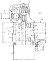
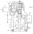
- the tensioning device is still and in a known manner from a head piece 1 with a pivotally mounted thereto clamping arm 2, which is connected via an actuating mechanism M with a drive actuator 3 in connection, wherein the head piece 1 spannarm- and recesses 4 for mounting the device a device carrier VT are arranged.
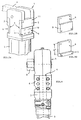
- each of the recesses 4 present on the head piece is provided with a connection plate 5, which, as shown in Fig. 3, fixed with screws 11 on the head piece 1 and in turn have Verschraubungstreatmentn 12 to set the device on the device carrier VT to be able to, which is indicated by dashed lines only in Fig. 1.
- FIG. 3 shows two identical connection plates 5 in FIG. 3A on the head piece 1.
- Fig. 3B shows a connection plate in reverse assignment possibility to the head piece 1 and the recess 4, which leads to this assignment that the distance D between the upper edge device carrier VT and lower edge UK clamping arm 2 (see Fig. 2) is correspondingly smaller.
- Fig. 3C illustrates that the recess 6 in its height H 'and, for example. In comparison to the recess 6 in Fig. 3B may be sized larger.
- connection design of a device carrier VT this can also be used directly in the recesses 4 and the device attached to it and fixed.
- connection plates 5 is provided on the connection side to the head piece 1 with fastening elements 7 for end position sensing elements 8 and also with connections for position signal transmission lines 10.
- this takes account of the fact that today usually End einsabfrageIAN for the two end positions (closing and opening position) of the clamping arm 2 are required for such but on the other hand on "normal" headers special measures for attaching appropriate, from a donor G on the linear actuator LG of the actuating mechanism M influenceable or switchable sensors (Endwolfsabfragemaschine 8) must be made, no matter what kind of sensors it is.
- the attachment problem of such sensors is also solved, and also variable, namely to the effect that when placed back on the device support VT (as shown in FIG. 1) the End einsabfrage emulate can be arranged on the tension arm side terminal plate 5 or the whole also vice versa, which should not preclude the End einsabfrage implant 8 to be arranged on the terminal plate 5, which establishes the connection to the device carrier VT.
- the arrangement of the sensors on the connection plate 5 is expediently provided, of course, which does not have to carry any supporting or holding function for the device in the particular case of attachment since this makes it easy to replace the sensors or position them even when the clamping device remains on the support can be.
Landscapes
- Engineering & Computer Science (AREA)
- Mechanical Engineering (AREA)
- Jigs For Machine Tools (AREA)
- Connection Of Plates (AREA)
- Clamps And Clips (AREA)
Claims (5)
- Dispositif de serrage pour serrer des pièces à usiner, composé d'une pièce de tête (1) avec un bras de serrage (2) logé de façon pivotante sur cette dernière, qui par l'intermédiaire d'un mécanisme de réglage (M) est en liaison avec un organe d'entraînement (3), des évidements (4) étant disposés côté bras de serrage et côté dos sur la pièce de tête (1) pour la fixation des dispositifs de serrage sur le support de dispositif (VT), les évidements (4) disposés dans la partie inférieure de la pièce de tête (1) s'étendant approximativement sous le logement du bras de serrage jusqu'à la zone de raccordement de l'organe d'entraînement (3) correspondant sensiblement par leur hauteur (H) s'étendant à la verticale jusqu'à la zone de raccordement à la longueur (L) de la partie inférieure de la pièce de tête (1'),
caractérisé en ce que dans au moins l'un des évidements (4), une plaque de raccord (5) est insérée de façon interchangeable et que pour sa part, cette dernière est munie d'évidements de raccord (6). - Dispositif de serrage selon la revendication 1,
caractérisé en ce que la disposition et la configuration des évidements de raccord (6) se correspondent sur les deux plaques de raccord (5). - Dispositif de serrage selon la revendication 1 ou 2,
caractérisé en ce
que les évidements de raccord (6) correspondent en leur hauteur (H') substantiellement à la moitié de la hauteur (H) des évidements (4) sur la pièce de tête (1). - Dispositif de serrage selon l'une des revendications 1 à 3,
caractérisé en ce
que les évidements de raccord sont placés dans la zone d'une moitié (HA) des plaques de raccord (5). - Dispositif de serrage selon l'une des revendications 1 à 4,
caractérisé en ce
qu'au moins l'une des plaques de raccord (5) est pourvue du côté du raccord à la pièce de tête (1) d'éléments de fixation (7) pour des éléments d'interrogation de fin de course (8) et de plus de raccords (9) pour des conduites d'émission de signaux de position (10).
Applications Claiming Priority (2)
| Application Number | Priority Date | Filing Date | Title |
|---|---|---|---|
| DE19757947 | 1997-12-27 | ||
| DE1997157947 DE19757947A1 (de) | 1997-12-27 | 1997-12-27 | Spannvorrichtung |
Publications (3)
| Publication Number | Publication Date |
|---|---|
| EP0925877A2 EP0925877A2 (fr) | 1999-06-30 |
| EP0925877A3 EP0925877A3 (fr) | 2001-05-02 |
| EP0925877B1 true EP0925877B1 (fr) | 2006-03-08 |
Family
ID=7853433
Family Applications (1)
| Application Number | Title | Priority Date | Filing Date |
|---|---|---|---|
| EP19980123547 Expired - Lifetime EP0925877B1 (fr) | 1997-12-27 | 1998-12-09 | Dispositif de serrage |
Country Status (3)
| Country | Link |
|---|---|
| EP (1) | EP0925877B1 (fr) |
| DE (2) | DE19757947A1 (fr) |
| ES (1) | ES2256911T3 (fr) |
Families Citing this family (5)
| Publication number | Priority date | Publication date | Assignee | Title |
|---|---|---|---|---|
| DE10137887B4 (de) * | 2001-08-02 | 2006-11-23 | Frank Entzmann | Spannvorrichtung |
| DE102011018205B3 (de) * | 2011-04-13 | 2012-10-04 | Armin Hofmann | Spannvorrichtung zum Spannen von Werkstücken |
| DE102011017425B9 (de) | 2011-04-13 | 2016-03-31 | Armin Hofmann | Spannvorrichtung zum Spannen von Werkstücken |
| DE202016000388U1 (de) | 2016-01-21 | 2016-02-29 | Christof Steubing | Spannvorrichtung mit exzentrisch gelagertem Drehpunkt des Spannhebels |
| CN111660236B (zh) * | 2020-05-22 | 2025-02-14 | 博格华纳汽车零部件(宁波)有限公司 | 一种压壳与中间体全自动定位装配工装 |
Family Cites Families (5)
| Publication number | Priority date | Publication date | Assignee | Title |
|---|---|---|---|---|
| US3545050A (en) * | 1969-01-30 | 1970-12-08 | I S I Mfg Inc | Power clamp with pull-back action |
| DE9000606U1 (de) * | 1990-01-20 | 1991-05-23 | De-Sta-Co Metallerzeugnisse Gmbh, 6000 Frankfurt | Spannvorrichtung |
| DE9215151U1 (de) * | 1992-05-14 | 1993-01-21 | De-Sta-Co Metallerzeugnisse Gmbh, 6000 Frankfurt | Spannvorrichtung |
| DE9412722U1 (de) * | 1994-08-06 | 1994-09-29 | DE-STA-CO Metallerzeugnisse GmbH, 61449 Steinbach | Kniehebelspannvorrichtung |
| DE29513131U1 (de) * | 1995-08-16 | 1996-12-12 | DE-STA-CO Metallerzeugnisse GmbH, 61449 Steinbach | Spannvorrichtung |
-
1997
- 1997-12-27 DE DE1997157947 patent/DE19757947A1/de not_active Withdrawn
-
1998
- 1998-12-09 EP EP19980123547 patent/EP0925877B1/fr not_active Expired - Lifetime
- 1998-12-09 DE DE59813426T patent/DE59813426D1/de not_active Expired - Lifetime
- 1998-12-09 ES ES98123547T patent/ES2256911T3/es not_active Expired - Lifetime
Also Published As
| Publication number | Publication date |
|---|---|
| DE59813426D1 (de) | 2006-05-04 |
| EP0925877A2 (fr) | 1999-06-30 |
| DE19757947A1 (de) | 1999-07-01 |
| ES2256911T3 (es) | 2006-07-16 |
| EP0925877A3 (fr) | 2001-05-02 |
Similar Documents
| Publication | Publication Date | Title |
|---|---|---|
| DE2654255C2 (de) | Spanneinrichtung für biegsame dünne Druckplatten auf mit Sattelplatten versehenen Plattenzylindern von Rollen-Rotationsdruckmaschinen | |
| EP0595074B1 (fr) | Dispositif de serrage | |
| DE19721752C2 (de) | Vorrichtung zum Einstellen der Spur bei Rädern von Kraftfahrzeugen | |
| DE29905687U1 (de) | Trageinrichtung | |
| DE3733849C1 (de) | Maschinenschraubstock mit Kraftverstaerker | |
| DE102005006398A1 (de) | Vorrichtung zum Greifen und Halten eines Bauteils | |
| DE602004007410T2 (de) | Verbessertes werkzeugsystem | |
| EP1924376B1 (fr) | Tourelle d'outil | |
| EP1155782A2 (fr) | Tête de soutien d'un dispositif de support pour tenir une piéce a travailler | |
| EP1815939B1 (fr) | Element de positionement pour unité de fixation avec des plaques de positionement et une console coulissant par un système rainure-ecrou en T ; Unité de fixation avec un tel élément de positionement | |
| EP0925877B1 (fr) | Dispositif de serrage | |
| DE3606036C2 (fr) | ||
| EP0873816B1 (fr) | Cylindre pour positionnement et serrage rapide | |
| EP3145676B1 (fr) | Capteur pour dispositif de serrage électrique | |
| DE202011106765U1 (de) | Vorrichtung zur Verbindung einer Front mit einer Zarge | |
| DE60002653T2 (de) | Vorrichtung zur verstellung einer platte auf einem zylinder mit magnetischen befestigungselementen | |
| CH710891A2 (de) | Wechsel-Nummernschildhalter. | |
| EP1617087A1 (fr) | Dispositif de support | |
| DE19837188C1 (de) | Koppelstück zum Anschluß an einer Tragstruktur eines Büromöbels | |
| DE9107104U1 (de) | Modulare Spannvorrichtung | |
| DE9411291U1 (de) | Spannvorrichtung | |
| EP1574284B1 (fr) | Actionneur linéaire | |
| DE2315724B2 (de) | Vorrichtung zur abstuetzung von werkstuecken bzw. werkzeugen | |
| DE202015105215U1 (de) | Trägersystem für Werkzeuge | |
| DE29705088U1 (de) | Bohrvorrichtung |
Legal Events
| Date | Code | Title | Description |
|---|---|---|---|
| PUAI | Public reference made under article 153(3) epc to a published international application that has entered the european phase |
Free format text: ORIGINAL CODE: 0009012 |
|
| AK | Designated contracting states |
Kind code of ref document: A2 Designated state(s): DE ES FR GB IT |
|
| AX | Request for extension of the european patent |
Free format text: AL;LT;LV;MK;RO;SI |
|
| PUAL | Search report despatched |
Free format text: ORIGINAL CODE: 0009013 |
|
| AK | Designated contracting states |
Kind code of ref document: A3 Designated state(s): AT BE CH CY DE DK ES FI FR GB GR IE IT LI LU MC NL PT SE |
|
| AX | Request for extension of the european patent |
Free format text: AL;LT;LV;MK;RO;SI |
|
| 17P | Request for examination filed |
Effective date: 20010908 |
|
| AKX | Designation fees paid |
Free format text: DE ES FR GB IT |
|
| 17Q | First examination report despatched |
Effective date: 20031103 |
|
| GRAP | Despatch of communication of intention to grant a patent |
Free format text: ORIGINAL CODE: EPIDOSNIGR1 |
|
| GRAS | Grant fee paid |
Free format text: ORIGINAL CODE: EPIDOSNIGR3 |
|
| GRAC | Information related to communication of intention to grant a patent modified |
Free format text: ORIGINAL CODE: EPIDOSCIGR1 |
|
| RAP1 | Party data changed (applicant data changed or rights of an application transferred) |
Owner name: DE-STA-CO EUROPE GMBH |
|
| GRAA | (expected) grant |
Free format text: ORIGINAL CODE: 0009210 |
|
| AK | Designated contracting states |
Kind code of ref document: B1 Designated state(s): DE ES FR GB IT |
|
| REG | Reference to a national code |
Ref country code: GB Ref legal event code: FG4D Free format text: NOT ENGLISH |
|
| GBT | Gb: translation of ep patent filed (gb section 77(6)(a)/1977) |
Effective date: 20060308 |
|
| REF | Corresponds to: |
Ref document number: 59813426 Country of ref document: DE Date of ref document: 20060504 Kind code of ref document: P |
|
| REG | Reference to a national code |
Ref country code: ES Ref legal event code: FG2A Ref document number: 2256911 Country of ref document: ES Kind code of ref document: T3 |
|
| ET | Fr: translation filed | ||
| PLBE | No opposition filed within time limit |
Free format text: ORIGINAL CODE: 0009261 |
|
| STAA | Information on the status of an ep patent application or granted ep patent |
Free format text: STATUS: NO OPPOSITION FILED WITHIN TIME LIMIT |
|
| 26N | No opposition filed |
Effective date: 20061211 |
|
| REG | Reference to a national code |
Ref country code: FR Ref legal event code: PLFP Year of fee payment: 18 |
|
| PGFP | Annual fee paid to national office [announced via postgrant information from national office to epo] |
Ref country code: DE Payment date: 20151113 Year of fee payment: 18 Ref country code: GB Payment date: 20151217 Year of fee payment: 18 |
|
| PGFP | Annual fee paid to national office [announced via postgrant information from national office to epo] |
Ref country code: ES Payment date: 20151120 Year of fee payment: 18 |
|
| PGFP | Annual fee paid to national office [announced via postgrant information from national office to epo] |
Ref country code: IT Payment date: 20151217 Year of fee payment: 18 |
|
| PGFP | Annual fee paid to national office [announced via postgrant information from national office to epo] |
Ref country code: FR Payment date: 20151231 Year of fee payment: 18 |
|
| REG | Reference to a national code |
Ref country code: DE Ref legal event code: R119 Ref document number: 59813426 Country of ref document: DE |
|
| GBPC | Gb: european patent ceased through non-payment of renewal fee |
Effective date: 20161209 |
|
| REG | Reference to a national code |
Ref country code: FR Ref legal event code: ST Effective date: 20170831 |
|
| PG25 | Lapsed in a contracting state [announced via postgrant information from national office to epo] |
Ref country code: FR Free format text: LAPSE BECAUSE OF NON-PAYMENT OF DUE FEES Effective date: 20170102 Ref country code: IT Free format text: LAPSE BECAUSE OF NON-PAYMENT OF DUE FEES Effective date: 20161209 |
|
| PG25 | Lapsed in a contracting state [announced via postgrant information from national office to epo] |
Ref country code: DE Free format text: LAPSE BECAUSE OF NON-PAYMENT OF DUE FEES Effective date: 20170701 Ref country code: GB Free format text: LAPSE BECAUSE OF NON-PAYMENT OF DUE FEES Effective date: 20161209 |
|
| PG25 | Lapsed in a contracting state [announced via postgrant information from national office to epo] |
Ref country code: ES Free format text: LAPSE BECAUSE OF FAILURE TO SUBMIT A TRANSLATION OF THE DESCRIPTION OR TO PAY THE FEE WITHIN THE PRESCRIBED TIME-LIMIT Effective date: 20060308 |
|
| REG | Reference to a national code |
Ref country code: ES Ref legal event code: FD2A Effective date: 20181113 |
|
| PG25 | Lapsed in a contracting state [announced via postgrant information from national office to epo] |
Ref country code: ES Free format text: LAPSE BECAUSE OF FAILURE TO SUBMIT A TRANSLATION OF THE DESCRIPTION OR TO PAY THE FEE WITHIN THE PRESCRIBED TIME-LIMIT Effective date: 20161210 |