EP0925935A2 - Procédé d'alimentation de liquide, dispositif, réservoir d'encre, cartouche et réservoir de remplissage et cartouche de tête utilisable avec ce dispositif - Google Patents
Procédé d'alimentation de liquide, dispositif, réservoir d'encre, cartouche et réservoir de remplissage et cartouche de tête utilisable avec ce dispositif Download PDFInfo
- Publication number
- EP0925935A2 EP0925935A2 EP98124667A EP98124667A EP0925935A2 EP 0925935 A2 EP0925935 A2 EP 0925935A2 EP 98124667 A EP98124667 A EP 98124667A EP 98124667 A EP98124667 A EP 98124667A EP 0925935 A2 EP0925935 A2 EP 0925935A2
- Authority
- EP
- European Patent Office
- Prior art keywords
- liquid
- negative pressure
- ink
- pressure producing
- liquid containing
- Prior art date
- Legal status (The legal status is an assumption and is not a legal conclusion. Google has not performed a legal analysis and makes no representation as to the accuracy of the status listed.)
- Granted
Links
- 239000007788 liquid Substances 0.000 title claims abstract description 576
- 238000000034 method Methods 0.000 title claims abstract description 26
- 239000000463 material Substances 0.000 claims abstract description 217
- 238000004891 communication Methods 0.000 claims abstract description 60
- 239000012530 fluid Substances 0.000 claims abstract description 44
- 230000033001 locomotion Effects 0.000 claims abstract description 27
- 230000007423 decrease Effects 0.000 claims abstract description 12
- 238000007789 sealing Methods 0.000 claims description 23
- 230000005489 elastic deformation Effects 0.000 claims description 3
- 230000006872 improvement Effects 0.000 claims description 3
- 239000000976 ink Substances 0.000 description 840
- 230000008859 change Effects 0.000 description 52
- 230000003068 static effect Effects 0.000 description 15
- 230000002829 reductive effect Effects 0.000 description 14
- 238000007599 discharging Methods 0.000 description 13
- 230000009467 reduction Effects 0.000 description 12
- 230000004308 accommodation Effects 0.000 description 11
- 230000006870 function Effects 0.000 description 11
- 230000000717 retained effect Effects 0.000 description 11
- 238000003825 pressing Methods 0.000 description 10
- 238000011084 recovery Methods 0.000 description 9
- 230000000694 effects Effects 0.000 description 8
- 230000008569 process Effects 0.000 description 7
- 230000000630 rising effect Effects 0.000 description 5
- 238000000071 blow moulding Methods 0.000 description 4
- 230000007246 mechanism Effects 0.000 description 4
- 230000005499 meniscus Effects 0.000 description 4
- 239000011148 porous material Substances 0.000 description 4
- 238000007639 printing Methods 0.000 description 4
- 230000009471 action Effects 0.000 description 3
- 238000004140 cleaning Methods 0.000 description 3
- 230000001419 dependent effect Effects 0.000 description 3
- 238000002347 injection Methods 0.000 description 3
- 239000007924 injection Substances 0.000 description 3
- 230000000670 limiting effect Effects 0.000 description 3
- 239000002184 metal Substances 0.000 description 3
- 229920005989 resin Polymers 0.000 description 3
- 239000011347 resin Substances 0.000 description 3
- 230000004044 response Effects 0.000 description 3
- 229920005830 Polyurethane Foam Polymers 0.000 description 2
- 239000011358 absorbing material Substances 0.000 description 2
- 238000010521 absorption reaction Methods 0.000 description 2
- 230000008901 benefit Effects 0.000 description 2
- 230000003139 buffering effect Effects 0.000 description 2
- 210000000078 claw Anatomy 0.000 description 2
- 239000003086 colorant Substances 0.000 description 2
- 230000003247 decreasing effect Effects 0.000 description 2
- 238000001514 detection method Methods 0.000 description 2
- 238000006073 displacement reaction Methods 0.000 description 2
- 238000009826 distribution Methods 0.000 description 2
- 239000000835 fiber Substances 0.000 description 2
- 229920001903 high density polyethylene Polymers 0.000 description 2
- 239000004700 high-density polyethylene Substances 0.000 description 2
- 238000007641 inkjet printing Methods 0.000 description 2
- 238000012986 modification Methods 0.000 description 2
- 230000004048 modification Effects 0.000 description 2
- 230000035699 permeability Effects 0.000 description 2
- 239000011496 polyurethane foam Substances 0.000 description 2
- 238000012545 processing Methods 0.000 description 2
- 230000001737 promoting effect Effects 0.000 description 2
- 239000007787 solid Substances 0.000 description 2
- 239000004743 Polypropylene Substances 0.000 description 1
- 239000004793 Polystyrene Substances 0.000 description 1
- 230000005540 biological transmission Effects 0.000 description 1
- 230000006835 compression Effects 0.000 description 1
- 238000007906 compression Methods 0.000 description 1
- 238000007796 conventional method Methods 0.000 description 1
- 230000003111 delayed effect Effects 0.000 description 1
- 229920001971 elastomer Polymers 0.000 description 1
- 230000005484 gravity Effects 0.000 description 1
- 229920005669 high impact polystyrene Polymers 0.000 description 1
- 239000004797 high-impact polystyrene Substances 0.000 description 1
- 230000036039 immunity Effects 0.000 description 1
- 238000001746 injection moulding Methods 0.000 description 1
- 239000010410 layer Substances 0.000 description 1
- 230000014759 maintenance of location Effects 0.000 description 1
- 238000004519 manufacturing process Methods 0.000 description 1
- 238000005259 measurement Methods 0.000 description 1
- 238000000465 moulding Methods 0.000 description 1
- 230000003287 optical effect Effects 0.000 description 1
- 239000000088 plastic resin Substances 0.000 description 1
- 229920013716 polyethylene resin Polymers 0.000 description 1
- -1 polypropylene Polymers 0.000 description 1
- 229920001155 polypropylene Polymers 0.000 description 1
- 229920002223 polystyrene Polymers 0.000 description 1
- 230000002265 prevention Effects 0.000 description 1
- 230000035939 shock Effects 0.000 description 1
- 239000002356 single layer Substances 0.000 description 1
- 230000006641 stabilisation Effects 0.000 description 1
- 238000011105 stabilization Methods 0.000 description 1
- 229920005992 thermoplastic resin Polymers 0.000 description 1
Images









Classifications
-
- B—PERFORMING OPERATIONS; TRANSPORTING
- B41—PRINTING; LINING MACHINES; TYPEWRITERS; STAMPS
- B41J—TYPEWRITERS; SELECTIVE PRINTING MECHANISMS, i.e. MECHANISMS PRINTING OTHERWISE THAN FROM A FORME; CORRECTION OF TYPOGRAPHICAL ERRORS
- B41J2/00—Typewriters or selective printing mechanisms characterised by the printing or marking process for which they are designed
- B41J2/005—Typewriters or selective printing mechanisms characterised by the printing or marking process for which they are designed characterised by bringing liquid or particles selectively into contact with a printing material
- B41J2/01—Ink jet
- B41J2/17—Ink jet characterised by ink handling
- B41J2/175—Ink supply systems ; Circuit parts therefor
- B41J2/17503—Ink cartridges
- B41J2/17556—Means for regulating the pressure in the cartridge
-
- B—PERFORMING OPERATIONS; TRANSPORTING
- B41—PRINTING; LINING MACHINES; TYPEWRITERS; STAMPS
- B41J—TYPEWRITERS; SELECTIVE PRINTING MECHANISMS, i.e. MECHANISMS PRINTING OTHERWISE THAN FROM A FORME; CORRECTION OF TYPOGRAPHICAL ERRORS
- B41J2/00—Typewriters or selective printing mechanisms characterised by the printing or marking process for which they are designed
- B41J2/005—Typewriters or selective printing mechanisms characterised by the printing or marking process for which they are designed characterised by bringing liquid or particles selectively into contact with a printing material
- B41J2/01—Ink jet
- B41J2/17—Ink jet characterised by ink handling
- B41J2/175—Ink supply systems ; Circuit parts therefor
- B41J2/17503—Ink cartridges
- B41J2/17513—Inner structure
Definitions
- the present invention relates to a liquid supply method and a liquid supply system using a negative pressure to supply liquid to an outside, and more particularly to a liquid supply method usable with a liquid ejection recording apparatus which effects printing on recording material using a recording head to which liquid is supplied, a liquid supply system, an exchange liquid accommodating container and head cartridge usable with such a system.
- a liquid supply method using a negative pressure for supplying liquid to the outside is known in an ink jet recording apparatus field, wherein for example an ink container for permitting supply of liquid to an ink ejection head with a negative pressure, and wherein the ink container is made integral with the recording head ((head cartridge).
- the head cartridge is classified into a type wherein the recording head and the ink container (ink accommodating portion) are normally integral, and a type wherein the recording means and the ink accommodating portion are separate, which are both separable relative to the recording device, and are made integral when they are used.
- the easiest way of producing the negative pressure is to use capillary force of a porous material.
- the ink container of this type is provided with a porous material such as sponge which is accommodated preferably under compression and which occupies the entirety of the inside of the container, and with an air vent for permitting smooth ink supply by introduction of the air during the printing.
- a porous material such as sponge which is accommodated preferably under compression and which occupies the entirety of the inside of the container, and with an air vent for permitting smooth ink supply by introduction of the air during the printing.
- this type involves a problem that ink accommodation efficiency per unit voltage is low since the porous member is used to retain the ink.
- EP0580433 which has been assigned to the assignee of this application has proposed an ink container including a negative pressure producing material chamber, an ink accommodating chamber (reservoir) and a fluid communication part therebetween, wherein the ink accommodating chamber is substantially hermetically sealed, and the negative pressure producing material chamber is open to the ambience.
- EP0581531 also proposes a structure wherein the above-described o is exchangeable.
- Such an ink container is advantageous in that air is permitted go into the ink accommodating chamber with discharge of the ink from the ink accommodating chamber into the negative pressure producing material chamber (air-liquid exchanging operation), so that ink can be supplied to the outside with a substantially constant negative pressure during the air-liquid exchanging operation.
- EP0738605 which has been assigned to the assignee of this application proposes a liquid accommodating container including a casing having a substantially prism configuration, and a liquid accommodating portion which is deformable with discharge of the liquid therefrom said accommodating portion having an outer shape similar or equivalent to an inner shape of the casing, wherein in each side of the prism-like shape, the thickness at the corner portions of the side is smaller than the central portion thereof.
- the accommodating portion deforms or contracts with the discharge of the liquid (without air-liquid exchange) so that liquid is supplied with the negative pressure.
- This container is advantageous in that position of the ink container is not limited as compared with an ink containing bladder which is conventional. Additionally, since the ink is directly retained (substantially without use of porous material), the ink accommodation efficiency is high.
- the ink container of the type having the negative pressure producing material chamber and the ink accommodating chamber has a fixed accommodation space.
- air-liquid exchange is used, by which the air is introduced into the ink accommodating chamber. Therefore, when the ink is supplied out into the negative pressure producing material chamber, the corresponding amount of the air is introduced, so that ink accommodating chamber contains both of the air and the ink.
- the air may expands due to the ambient condition change (temperature variation during 24 hours) with the result that ink is discharged into the negative pressure producing material chamber from the ink accommodating chamber. Therefore, a buffer space has to be provided in the negative pressure producing member or material in consideration of a practically maximum volume determined by the expansion and the resulting amount of ink motion in various conditions.
- the ink discharge from the ink accommodating chamber into the negative pressure producing material chamber is directly interrelated with the introduction of the air through the communicating portion, and therefore, when a large amount of the ink is discharged from the negative pressure producing material chamber to the outside (liquid ejecting head) in a short period of time, the ink supply from the ink accommodating chamber into the negative pressure producing material chamber with the air-liquid exchanging operation is unlikely to follow the abrupt ink consumption.
- the inventors have analyzed in detail the ink accommodating chamber containing the air in an ink container having the negative pressure producing material chamber, the ink accommodating chamber and the communication port therebetween. The supply of the ink from the ink accommodating chamber into the negative pressure producing material chamber occurs in interrelation with the introduction of the air.
- the expansion of the air in the ink. accommodating chamber is unavoidable, but the inventors have considered allowing the expansion of the air in the ink accommodating chamber.
- a liquid supply method comprising a step of preparing a negative pressure producing material chamber, including a liquid supply portion for permitting supply of the liquid to an outside and an air vent for fluid communication with ambience, for accommodating a negative pressure producing member for retaining the liquid; a step of preparing a liquid containing chamber having a liquid containing portion for accommodating the liquid, said liquid containing portion forming a substantially sealed space except for fluid communication with the negative pressure producing material chamber; a first liquid supply step of permitting supply of the liquid to the outside by permitting movement of the liquid into said negative pressure producing material chamber from said liquid containing portion without introduction of the air into the liquid containing chamber with a negative pressure while permitting decrease of a volume of said liquid containing portion; a second liquid supply step, after said first liquid supply step, of permitting supply of the liquid to the outside by permitting movement of the liquid into said negative pressure producing material chamber from said liquid containing portion with introduction of the air into the liquid containing portion.
- the liquid containing portion deforms while maintaining a balance in the negative pressure with the negative pressure producing member. Therefore, even if the air expands in the liquid containing portion due to the ambient condition change, the liquid containing portion restores its shape upon an abrupt change so that influence of the change can be decreased. If the change is not abrupt, the influence of the expansion can be decreased by both of the negative pressure producing member and the liquid containing portion while the balance is eventually maintained with the negative pressure producing member. Therefore, the voltage of the buffer space in the negative pressure producing material chamber can be reduced even in view of various use condition.
- the air is introduced into the liquid containing portion, so that liquid in the liquid containing portion is used up substantially without an unusable remaining amount ink, and the negative pressure difference between at the time of the start of the liquid discharge from the liquid containing portion and at the time of the end thereof, can be smaller than that when the liquid containing portion alone is used as a negative pressure producing container.
- the ink accommodating chamber and the communication port therebetween the allowance to the air expansion is larger. Even if a large amount of the ink is consumed in a short period of-time, the liquid supply from the liquid containing portion into the negative pressure producing material chamber is smooth since the liquid containing portion is deformable.
- a liquid supply system using a liquid supply container including a liquid containing portion for accommodating liquid in a sealed space; a negative pressure producing material container, which accommodating container is detachably mountable relative to the liquid supply container and which is capable of effecting air-liquid exchange wherein air is introduced into said liquid containing portion, and the liquid is discharged through a communicating portion communicating with said liquid accommodating portion; the improvement comprising: said liquid containing portion of said liquid supply container is capable of producing a negative pressure while deforming; and wherein when the liquid supply container is mounted to said negative pressure producing material chamber, the liquid is permitted to move from said liquid containing portion into said negative pressure producing material chamber.
- the liquid can be moved from the liquid accommodating container into the negative pressure producing member using the capillary force in the negative pressure producing material chamber upon the mounting of the liquid accommodating container to the negative pressure producing material chamber, so that liquid in the exchanged liquid accommodating container can be assuredly used by the simple mounting, irrespective of the liquid retaining state of the negative pressure producing member adjacent the connecting portion.
- a practical liquid supply system with stabilized liquid supply can be provided.
- the present invention provides an ink container and an ink jet cartridge usable with the liquid supply method and the liquid supply system.
- a liquid container comprising a negative pressure producing material chamber, including a liquid supply portion for permitting supply of the liquid to an outside and an air vent for fluid communication with ambience, for accommodating a negative pressure producing member for retaining the liquid; a liquid containing chamber having a liquid containing portion for accommodating the liquid, said liquid containing portion forming a substantially sealed space except for fluid communication with the negative pressure producing material chamber; wherein said liquid containing portion deforms with discharge of the liquid therefrom while producing a negative pressure.
- the ink jet cartridge provided by the present invention comprises the above-described ink container and a recording head for effecting recording by ejecting the liquid to the outside. Further, the present invention provides an exchange liquid accommodating container usable with the liquid supply system.
- a liquid accommodating container detachably mountable relative to a negative pressure producing material container, having a liquid supply portion for supplying liquid to an outside and an air vent for fluid communication with ambience, for accommodating a negative pressure producing member for retaining the liquid, comprising a liquid containing portion for accommodating the liquid, which forms a substantially sealed space except for fluid communication with the negative pressure producing material chamber; and sealing means for sealing said communicating portion relative to said negative pressure producing material chamber.
- a liquid accommodating container detachably mountable relative to a negative pressure producing material container, having a liquid supply portion for supplying liquid to an outside and an air vent for fluid communication with ambience, for accommodating a negative pressure producing member for retaining the liquid, comprising a liquid containing portion for accommodating the liquid, which forms a substantially sealed space except for fluid communication with the negative pressure producing material chamber; and a casing having an inner shape equivalent or similar to an outer shape of said liquid containing portion and having an air vent for introducing the ambience; sealing means for sealing said communicating portion relative to said negative pressure producing material chamber.
- the present invention is suitably applicable to a head cartridge used in an ink jet recording field.
- a head cartridge comprising a recording head for ejecting the liquid; a negative pressure producing material chamber, including a liquid supply portion for permitting supply of the liquid to said recording head and an air vent for fluid communication with ambience, for accommodating a negative pressure producing member for retaining the liquid; a liquid containing chamber having a liquid containing portion for accommodating the liquid, said liquid containing portion forming a substantially sealed space except for fluid communication with the negative pressure producing material chamber; and wherein said liquid containing portion deforms with discharge of the liquid therefrom while producing a negative pressure; wherein said recording head and said negative pressure producing material chamber are integral with each other.
- a further aspect of the present invention provides a further method. More particularly, it provides a liquid supply method comprising a step of preparing a negative pressure producing-material chamber, including a liquid supply portion for permitting supply of the liquid to an outside and an air vent for fluid communication with ambience, for accommodating a negative pressure producing member for retaining the liquid; a step of preparing a liquid containing chamber-having a liquid containing portion for accommodating the liquid, said liquid containing portion forming a substantially sealed space except for fluid communication with the negative pressure producing material chamber; a step of moving the liquid from said liquid containing portion into said negative pressure producing material chamber without introduction of air into said liquid containing chamber with a negative pressure while permitting decrease of a volume of said liquid containing portion.
- the liquid in the liquid containing portion is usable without introduction of the air into the liquid containing portion, and therefore, even if the limitation to the inside volume of the liquid containing chamber is eased, change of the ambience is accommodatable.
- the negative pressure producing material container and the liquid accommodating container are generally used where they are separable from each other, and the negative pressure producing material chamber and the liquid containing chamber are used when they are separable or not separable.
- the region not filled with the liquid adjacent the air vent of the first chamber means a part the negative pressure producing member not filled with the ink as well as the space not having the negative pressure producing member (buffer portion).
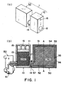
- Figure 1 is a schematic illustration of an ink container applicable with a liquid supply system according to a first embodiment of the present invention, wherein (a) is a perspective view thereof, and (b) is a sectional view thereof.
- Figure 2 is a schematic illustration of an ink accommodating chamber and an accommodating chamber for a negative pressure producing material when they are connected.
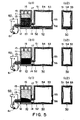
- Figure 3 is a schematic illustration for illustrating a first ink supply state in the ink container shown in Figure 1.
- Figure 4 is a schematic illustration for illustrating a second ink supply state (air-liquid exchanging state) in the ink container shown in Figure 1.
- Figure 5 is a schematic illustration illustrating a change in the container when the liquid is discharged after the second ink supply state shown in Figure 1.
- Figure 6 is an illustration showing a relation between the amount of ink discharge and the negative static pressure at an ink supply in the ink container shown in Figure 1.
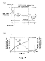
- Figure 7 (a) is a detailed illustration of a negative pressure curve shown in Figure 6; (b) shows a change of an amount of ink discharge from an ink accommodating portion and an amount of introduced air into the ink accommodating portion with time when the air is continuously discharged.
- Figure 8 is a detail illustration of an A region shown in Figure 7.
- Figure 9 is an illustration of operation of an ink container as regards the A region shown in Figure 7.
- Figure 10 is a detail illustration as to B region shown in Figure 7.
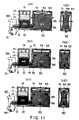
- Figure 11 is an illustration of operation of an ink container as to B region shown in Figure 7.
- Figure 12 illustrates operation during exchange of the ink accommodating chamber.
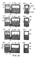
- Figure 13 is an illustration of a mechanism of stabilized liquid retention when an ambient condition is changed in the ink container shown in Figure 1.
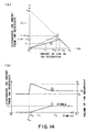
- Figure 14 is an illustration of an amount of ink discharging when the pressure in the ink container shown in Figure 1 is reduced, wherein (a) is an illustration of a relation between a volume of an initial space of the ink accommodating chamber before the pressure reduction and an amount of ink discharging upon pressure reduction, and (b) show an amount of ink discharge from the ink accommodating portion and a change, with time, of the volume of the ink accommodating portion when the ambience pressure of the container is changed from ambient pressure to P atm. (0 ⁇ P ⁇ 1) (pressure-reduced state).
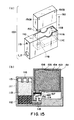
- Figure 15 is a schematic illustration of an ink container usable with the liquid supply system of the present invention according to a second embodiment, wherein (a) is a perspective view thereof, and (b) is a sectional view thereof.
- Figure 16 is a schematic illustration of an ink container usable with a liquid supply system according to a third embodiment.
- Figure 17 is a schematic illustration of a modified example of an ink container usable with a liquid supply system of the present invention.
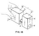
- Figure 18 is a schematic illustration of pressing the ink accommodating portion.
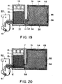
- Figure 19 is a schematic sectional view of a modified example of an ink container usable with the liquid supply system of the present invention.
- Figure 20 is a schematic sectional view of a modified example of an ink container usable with a liquid supply system of the present invention.
- Figure 21 is a schematic illustration of an example of an ink jet recording apparatus usable with a liquid supply system of the present invention.
- ink is taken as an example of the liquid usable with the liquid supply method and the liquid supply system according to the present invention, but the present invention is not limited to the ink but is usable with processing liquid to be applied on the recording material in the ink jet recording field, for example.
- Figure 1 is a schematic illustration of an ink container applicable with a liquid supply system according to a first embodiment of the present invention, wherein (a) is a perspective view thereof, and (b) is a sectional view thereof.
- the ink container 1 comprises an accommodating chamber for the negative pressure producing material 10 and an ink accommodating chamber 50, and the ink accommodating chamber 50 is separable from the negative pressure producing material chamber 10 through a communication tube(air-liquid exchange passage) 14.
- the negative pressure producing material chamber 10 a casing member 11 having an ink supply port 12 for supplying the ink (or processing liquid or the like) into an outside means such as a recording head 60 for effecting recording by ejecting liquid through an ejection outlet 61, a negative pressure producing member or material 13 of porous member or material such as polyurethane foam accommodated therein, and a communication tube(air-liquid exchange passage) 14, contacted to the negative pressure generating member, for introducing liquid from the second chamber.
- the casing 11 comprises an ambience introducing groove 17, on an inside of the communication tube, for promoting air-liquid exchange which will be described hereinafter, an air vent 15 for fluid communication between the ambience and the negative pressure producing member accommodated therein, and there is provided a buffer portion 16 in the form of a rib projected from the inner surface of the casing adjacent the air vent 15.
- the air-liquid exchange passage 14 is contacted to the negative pressure producing member 13, and the end thereof communicates with the air introducing groove 17, so that smooth liquid supplying operation which will be described hereinafter is accomplished.
- the ink accommodating chamber 50 comprises a casing member(outer wall) 51 constituting a chamber, and ink accommodating portion 53, constituted by a wall(inner wall) 54 having an inner surface similar to or equivalent to the inner surface of the casing member, for accommodating the ink therein, an ink discharging outlet 52 communicating with the air-liquid exchange passage 14 of the accommodating chamber for the negative pressure producing material, for discharging the liquid from the liquid containing portion 53 into the negative pressure producing material chamber.
- an unshown seal member such as an O-ring is provided at a connecting portion between the ink discharging outlet 52 and the air-liquid exchange passage 14, by which the ink leakage and the introduction of the ambience through the connecting portion, is prevented.
- the seal member is satisfactory if it is provided at one of the ink accommodating chamber and the negative pressure producing material chamber, or it may be provided at each of them to enhance the sealing property. It may be provided independently of the ink accommodating chamber and the negative pressure producing material chamber, and it may be engaged with the connecting portions of them upon necessity.
- the inner wall 54 has a flexibility, and the ink accommodating portion 53 is deformable with the discharge of the ink accommodated therein.
- the inner wall 54 has a welded portion(pinch-off portion) 56, and the inner wall is supported on the outer wall with engagement therebetween at the welded portion.
- the outer wall is provided with an ambience communication port 55 to permit introduction of the ambience to between the inner wall and the outer wall.
- the hatched portion indicates the region of the negative pressure producing member retaining the ink.
- the cross-hatched portion indicates the ink contained in the space such as the ink accommodating portion, the air introducing groove and the air-liquid exchange passage.
- the ink accommodating chamber of this embodiment is defined by 6 flat surfaces which constitute a substantially rectangular parallelopiped configuration, to which a cylindrical ink discharging outlet 52 is added in the form of a curved surface, and the maximum area side of the rectangular parallelopiped configuration is indirectly shown in Figure 1.
- the thickness of the internal wall surface 53 is thinner in the portion constituting the apex portions, which will be called corner portions (including the rounded corner with small radius of curvature) than the central region of each of the sides of the rectangular parallelopiped shape, and the thickness gradually decreases from the central region of each of the sides toward the corner portions, and the configuration is convex inwardly of the ink accommodating portion.
- the direction is the same as the direction of deformation of the sides, so that deformation is promoted, as will be described hereinafter.
- Each of the corner portions of the inner wall is constituted by three sides, so that strength of the entirety of the corner portions of the inner wall is greater than that of the central regions. As seen from an extension of the sides, since the thickness of the corner portions is smaller than of the central region, movement of the sides are permitted. It is desirable that portions constituting the corner portions of the inner walls have substantially equivalent thicknesses. Since Figure 1 is relatively schematic, there is a space between the outer wall 51 of the ink accommodating chamber and the inner wall 52 thereof, but they may be contacted to each other or spaced from each other, if they are separable.
- the ink accommodating chamber of the ink container may be of an exchangeable structure relative to the negative pressure producing material chamber.
- Figure 2 shows an example of changes of each of the chambers in a connecting operation between the ink accommodating chamber and the negative pressure producing material chamber of the ink container shown in Figure 1, suffix 1 indicates that Figure is a sectional view in the same direction as with Figure 1, (b), and suffix 2 indicates that Figure is a sectional view (A-A) of the liquid containing chamber shown in Figure 1, (b).
- Figure 2(a1), (a2) show the states of the negative pressure producing material chamber and the ink accommodating chamber before the connection therebetween.
- the ink discharging outlet 52 of the liquid containing chamber 50 is provided with a sealing means 57 (for example film) for preventing discharge of the ink accommodated in the ink accommodating portion, so that ink accommodating portion of the liquid containing chamber is maintained sealed against the atmosphere.
- the inner wall 54 constituting the ink accommodating portion is formed such that it is extended along the inner surface configuration of the casing(outer wall) 51 and that corner portion of the inner wall is close to the corner portion of the outer wall. This state is called here " initial state".
- the ink accommodating portion may contain an amount of the ink which is slightly smaller than the maximum capacity thereof, since then the ink is more assuredly prevented from leaking out due to the temperature change and/or pressure change, when the sealing means is unsealed.
- the amount of the air accommodated in the ink accommodating portion before the connection to the negative pressure producing material chamber is desirably very small.
- a liquid injection method may be used, as disclosed in Japanese Laid-open Patent Application No. HEI- 10-175311.
- the negative pressure producing member of the negative pressure producing material chamber retains the ink in a part thereof.
- the interface of the ink accommodated in the negative pressure producing member is that in the case of it being lower than the air introducing groove, and the air introducing groove is in fluid communication with the ambience through the negative pressure producing member.
- the amount of the ink accommodated in the negative pressure producing member is dependent on the amount of the ink accommodated in the negative pressure producing member when the ink accommodating chamber is exchanged, which will be described hereinafter, and therefore, it may be different slightly, and it is not inevitable that ink is retained in the uniform state as shown in the Figure.
- the air introducing groove and the air-liquid exchange passage are not required to be filled with the liquid, and may contain the air as shown in Figure 2(al).
- the ink accommodating chamber is connection to the negative pressure producing material chamber.
- the ink accommodating portion 53 flows into the air-liquid exchange passage 14, and an ink path is established between the negative pressure producing material chamber and the negative pressure producing member 13.
- the ink movement from the ink accommodating portion to the negative pressure producing member is started as shown in Figure 2(bl) by the capillary force of the negative pressure producing member, by which the interface (level of liquid) of the negative pressure producing member rises.
- the inner wall 54 tends to deform from the central portion of the major side (maximum area side) in a direction of decrease of the volume of the ink accommodating portion 53.
- the outer wall 51 functions to retard displacement of the corner portions of the inner wall 54, and therefore, the ink accommodating portion receives the force due to the ink consumption and rebounding force toward the initial state ( Figure 2(al), (a2)), so that negative pressure is generated in accordance with the degree of deformation without abrupt change.
- the space between the inner wall and the outer wall is in fluid communication with the ambience through the ambience communication port 55, so that air is introduced into between the inner wall 54 and the outer wall 51 in accordance with the deformation.
- the ink in the ink accommodating portion is contacted to the negative pressure producing member by which an ink path is formed, and therefore, the ink accommodating portion deforms with the discharge of the ink, so that air easily moves into the ink accommodating portion 53.
- the ink is supplied thereinto when the capillary force of the air introducing groove is larger than the negative pressure generated by the ink accommodating portion, as in this embodiment.
- the ink is supplied into the negative pressure producing member, and then, as shown in Figure 2, (c1), the ink is filled up to above the top end portion of the ambience introduction groove, so that fluid communication of the ambience introduction groove with the ambience is shut.
- the ink accommodating chamber receives and discharges the ink and the air only through the negative pressure producing material chamber, so that ink further moves so that negative static pressure in the air-liquid exchange passage of the ink accommodating chamber and the negative static pressure in the air-liquid exchange passage of the negative pressure producing material chamber.
- the movement of the ink from the ink accommodating chamber to the negative pressure producing material chamber when the ink accommodating chamber and the negative pressure producing material chamber are connected is carried out without introduction of the air into the ink accommodating chamber through the negative pressure producing member.
- the negative static pressures in the respective chambers in the balanced state is properly selected so that ink does not leak out of a liquid ejection recording means(unshown) such as a recording head connected to the ink supply port, depending on the nature of the liquid ejection recording means connected thereto ( Figure 6 a) by one skilled in the art.
- the lower limit of the amount of the ink which is movable from the ink accommodating portion is the amount of the ink when the ink supply is carried out into the negative pressure producing member up to the upper limit level of the air introducing groove (air-liquid interface negative pressure producing member which will be described hereinafter), and the upper limit is the amount up to the complete ink filling into the negative pressure producing member.
- the amount of the ink moving to the negative pressure producing member on the basis of the amounts of the upper limit and the lower limit of the ink in consideration of the variation of the amount of the ink retained in the negative pressure producing member before the connection. By doing so, the material and the thickness of the ink accommodating portion can be properly selected for the negative pressure producing member on the basis of the negative pressure value a in the balanced state.
- a part of the negative pressure producing member may remain unsupplied with the ink even if the balanced state is reached as shown in Figure 2(c1) and Figure 2(c2).
- Such a part can be used as a buffer region which functions together with the buffer portion, when the temperature and/or the pressure varies, which will be described hereinafter.
- suction recovery means which will be described hereinafter and which is provided in the main assembly of the liquid ejection recording device, is used to discharge a small amount of the ink.
- the establishment of the ink path in the air-liquid exchange passage upon the connecting operation may be effected using a mechanical impact given at the time of the connecting action.
- the ink accommodating portion is pressurized by for example pressing the casing of the ink accommodating portion, as shown in Figure 18.
- the ink accommodating portion is placed under a slight negative pressure state, and by the ink accommodating portion being brought into fluid communication with the ambience through the air introducing groove upon the connection, the air in the air-liquid exchange passage is promoted to move into the ink accommodating portion using deformation of the ink accommodating portion by the variation of the pressure.
- a part of the air in the passage may move into the ink accommodating portion, depending on the configuration of the air-liquid exchange passage and/or the presence or absence of the air in the passage before the connection, but such a slight movement of the air into the ink accommodating portion is permissible.
- Figures 3-6 show an example of states of the ink container when the liquid is consumed by the recording head connected to the ink container in the state at start of use shown in Figures 2, (c1), (c2).
- Figures 3-5 show an example of the changes of the ink accommodating chamber and the negative pressure producing material chamber with the consumption of the liquid from the ink container, in the order of Figure 3, (a)-(c), Figure 4, (a)-(c) and Figure 5, (a)-(c), wherein suffix 1 indicates the sectional plane which is the same as that of Figure 1, (b); suffix 2 indicates the sectional plane A-A of the liquid containing chamber in Figure 1, (b).
- Figure 6 illustrates a relation between the ink discharge amount of the ink container shown in Figure 1 and the negative pressure of the ink supply port, wherein the abscissa represents an ink discharge amount from the ink supply port to the outside, and the ordinate is a negative pressure(negative static pressure) of the ink supply port.
- the change of the negative pressure shown in Figures 2-5 is indicated by arrow.
- the ink supply operation can be understood in the three modes, more particularly, before the start of air-liquid exchanging operation shown in Figure 3, during (mainly) air-liquid exchanging operation shown in Figure 4 and after air-liquid exchanging operation shown in Figure 5.
- the respective operations are described in detail using the Figures.
- the liquid level in the negative pressure producing member in the negative pressure producing material chamber lowers with the consumption of the ink through the ink supply port, and the central portions of the ink accommodating portion stably deforms inwardly.
- the portion not having the pinch-off portion starts deformation and separates from the outer wall earlier than the portion having the pinch-off portion 104, in order to reach the balance in the negative pressure between the ink accommodating portion and the negative pressure producing member.
- the pinch-off portion 56 functions in effect as one of deformation limiting portions against the inner wall 54.
- the change of the negative static pressure relative to the amount of the ink discharge through the ink supply port in the air-liquid exchange state substantially does not occur (substantially constant negative static pressure) as indicated by B in Figure 6, thus supplying the ink to the liquid ejection recording means with stability.
- Figure 6 is schematic, and the negative pressure is not strictly constant in the air-liquid exchange region.
- the ink accommodating chamber per se can be contributable to the generation of the negative pressure by the deformation of the ink accommodating portion.
- the bubble of the air-liquid exchange stagnates in the air-liquid exchange path, and the bubble moves into the ink accommodating portion when the amount thereof reaches a certain level, depending on the kind of the ink. This is also a cause of the negative pressure variation upon the movement of the bubble, but the variation is tolerable when the liquid container is used with an ink jet recording apparatus. This is also the air-liquid exchange state.
- the air-liquid exchange path may be temporarily kept plugged by the bubble even if the ink level in the ink accommodating portion lowers beyond the top end portion of the air-liquid exchange path as shown in Figure 4(c1), (c2).
- the ink accommodating portion deforms more toward the initial state than in the air-liquid exchange state shown in Figure 4(b1)and 4(b2).
- the ink is supplied into the negative pressure producing member immediately with the introduction of the ambience into the ink accommodating chamber.
- the ink may be supplied into the negative pressure producing member without the introduction of the ambience into the ink accommodating chamber.
- the ink may not be supplied into the negative pressure producing member immediately after the introduction of the ambience into the ink accommodating chamber with the consumption of the ink. This depend on the negative pressure balance between the displacement of the ink accommodating chamber and the negative pressure producing material chamber.
- timing of the air-liquid exchanging operation may be different from that in the conventional ink container, and by the time difference between the ink discharge from the ink accommodating portion and the introduction of the air into the ink accommodating portion upon the air-liquid exchange, the stable ink supply is more reliable because of the buffer effect and the timing deviation even upon external factors such as abrupt ink consumption, ambient condition change, vibration.
- the ink level in the ink accommodating portion becomes lower than the upper end of the air introducing groove, so that ink accommodating portion becomes in complete fluid communication with the air-liquid exchange path, as shown in Figure 5(a1), (a2).
- the ink accommodating portion deforms more toward the initial state than in the air-liquid exchange state by the communication with the ambience.
- the configuration does not completely restores, and it is in a slightly deformed state.
- the air-liquid exchange path has a large diameter, and therefore, a small amount of the ink remaining in the ink accommodating portion is absorbed by the negative pressure producing member with the result of rising of the liquid level in the negative pressure producing member, so that negative pressure temporarily lowers. Thereafter, the air-liquid exchange path is sealed by the ink in the negative pressure producing material, the ink is consumed similarly to the air-liquid exchanging operation described hereinbefore.
- the ink moves until the pressures of negative pressure producing material chamber and the ink accommodating chamber becomes equal so that state at start of use is established.
- the ink consumption by the liquid ejection recording means is started thereafter, the ink is consumed both from the ink accommodating portion and the negative pressure producing member while the rising negative static pressures are balanced therebetween.
- the air-liquid exchange state occurs wherein the ink is discharged with a substantially constant negative pressure while the air-liquid interface of the negative pressure producing member is maintained by the introduction of the air into the ink accommodating portion, and finally, the ink remaining in the negative pressure producing material chamber is consumed.
- the air-liquid exchanging operation can be effected at different timing from that in the air-liquid exchange of the prior art, the ink supply is possible in other than normal state.
- the ink can be substantially completely consumed from the ink accommodating chamber, and in addition, the air-liquid exchange passage may contain the air when the ink container is exchanged, and the ink accommodating chamber can be exchanged irrespective of the amount of the ink retained in the negative pressure producing member. Therefore, the ink accommodating chamber is easily exchangeable without use of the remaining amount detecting mechanism.
- the ink supply performance of the ink container has be checked.
- a negative pressure producing member having a pore size of approx 60 / inch is placed in the negative pressure producing material chamber having inner dimensions of 48mm x 46mm x 10mm approx, and the air-liquid exchange path is in the form of a hollow pipe having an inner diameter of approx 7mm.
- the negative pressure producing material chamber is connected to an ink accommodating chamber including an outer wall of shock resistant polystyrene (HIPS) resin material having a maximum thickness of approx lmm and an inner wall of high density polyethylene (HDPE) resin material having a maximum thickness of approx 150 ⁇ m and having a volume approx 30cm 3 .
- HIPS shock resistant polystyrene
- HDPE high density polyethylene
- Figure 7 shows details of an actual example of the negative pressure curve of Figure 6, and (1), (2), (3) in the Figure corresponds to the (1), (2), (3) in the foregoing disclosure of the operations.
- Figure 8 shows a detail of an example of A region in Figure 7;
- Figure 9 illustrates the operation of the ink container in the A region in Figure 7 in the order of (a)-(c);
- Figure 10 shows an example of B region in Figure 7;
- Figure 11 shows the operation of the ink container in the B region in Figure 7 in the order of (a)-(c).
- suffix 1 indicates a sectional view along the same line as with Figure 1, (b), and suffix 2 indicates a sectional view taken along a line A-A of the liquid containing chamber in Figure 1, (b).
- the deformation or the like of the ink accommodating chamber is more or less exaggerated.
- This region (before air-liquid exchanging operation) is disclosed in the folIowing three patterns.
- the patterns are within the present invention, and are dependent on the capillary force of the negative pressure producing member, the thickness, material or the like of the ink accommodating chamber portion and the balance.
- This pattern occurs generally when the ink accommodating chamber rather than the negative pressure producing member is ruling in the negative pressure control. More particularly, when the thickness of the ink accommodating chamber portion is relatively thick, or when the rigidity of the inner wall of the ink accommodating chamber portion is relatively high, this pattern tends to occur.
- the ink In the ink discharge from the initial state, the ink is discharged from the negative pressure producing member. This is because the resisting force against the discharge of the ink from the negative pressure producing member is smaller than the resisting force against the discharge of the ink from the ink accommodating chamber. After the ink is first discharged from the negative pressure producing member, the ink is discharged from the respective chambers while balance is maintained therebetween. When the ink is discharged from the ink accommodating chamber, the inner wall is deformed inwardly.
- This pattern tends to occur when the negative pressure producing member rather than the ink accommodating chamber is ruling in the negative pressure control, contrary to the case of the first pattern. More particularly, this case tends to occur when the inner wall of the ink accommodating chamber is relatively thin, or when the rigidity of the inner wall is small.
- the ink In the discharge of the ink in the initial state, the ink is first discharged from the ink accommodating chamber. This is because the resisting force against the discharge of the ink from the ink accommodating chamber is smaller than the resisting force against the discharge of the ink from the negative pressure producing member. Thereafter, the ink is discharged from the negative pressure producing member and the ink accommodating chamber while balance is maintained therebetween.
- This pattern occurs generally when the ink accommodating chamber rather than the negative pressure producing member is ruling in the negative pressure control. More particularly, when the thickness of the ink accommodating chamber portion is relatively thick, or when the rigidity of the inner wall of the ink accommodating chamber portion is relatively high, this pattern tends to occur.
- the ambience is introduced from the negative pressure producing material chamber into the ink accommodating chamber ( Figure 8a region) This is to balance the negative pressures.
- the inner wall of the ink accommodating chamber slightly deforms outwardly, as shown in Figure 9a.
- the ink is supplied into the negative pressure producing material chamber from the ink accommodating chamber, so that liquid level in the negative pressure producing material chamber slightly rises.
- the ink is first discharged from the negative pressure producing member in this example.
- the liquid level in the negative pressure producing material chamber lowers as shown in the Figure.
- This pattern tends to occur when the negative pressure producing member rather than the ink accommodating chamber is ruling in the negative pressure control, contrary to the case of the first pattern. More particularly, this case tends to occur when the inner wall of the ink accommodating chamber is relatively thin, or when the rigidity of the inner wall is small.
- the ambience is introduced into the ink accommodating chamber from the negative pressure producing material chamber in the air-liquid exchanging operation region (region a in Figure 10).
- region a in Figure 10 the ambience is introduced into the ink accommodating chamber from the negative pressure producing material chamber in the air-liquid exchanging operation region.
- the inner wall of the ink accommodating chamber slightly deforms outwardly, as shown in Figure lla.
- the ink is supplied into the negative pressure producing material chamber from the ink accommodating chamber, so that liquid level in the negative pressure producing material chamber slightly rises.
- the ink is mainly discharged from the ink accommodating chamber in this pattern.
- the negative pressure does not change greatly and therefore gradually increases because of the thickness and the rigidity of the ink accommodating chamber.
- the inner wall of the ink accommodating chamber gradually deforms inwardly (region b in Figure 10). In this region, the ink is hardly discharged from the negative pressure producing member, and therefore, the liquid level of the negative pressure producing member hardly changes.
- region b when the ink is further discharged, the ink is discharged from both of the negative pressure producing member and the ink accommodating chamber while the balance is maintained therebetween (region c of Figure 10).
- region c of Figure 10 the liquid level of the negative pressure producing member lowers, and the inner wall of the ink accommodating chamber deforms inwardly (region c of Figure 10) ( Figure 11c).
- the ambience is introduced into the ink accommodating chamber through the ambience introduction path, so that state of Figure 10a occurs.
- region (3) in Figure 7 after the air-liquid exchange region will be described. After the air-liquid exchange ends, that is, most of the ink in the ink accommodating chamber is discharged, the ink is discharged only from the negative pressure producing member. This region is divided into the following two patterns.
- the ink in the ink accommodating chamber is hardly discharged.
- a meniscus is generally formed in the air vent path, the fluid communication path between the negative pressure producing material chamber and the ink accommodating chamber or in the negative pressure producing member.
- the ink accommodating chamber is brought into a fluid communication with the ambience through the air vent path.
- the pressure in the ink accommodating chamber becomes substantially ambient pressure.
- the inner wall of the ink accommodating chamber having been deformed inwardly tends to restore by the elasticity of itself.
- the liquid level in the negative pressure producing member lowers by the discharge of the ink in the negative pressure producing member.
- the negative pressure increases substantially proportionally.
- the ink accommodating chamber maintains the negative pressure state.
- the inside of the ink accommodating chamber is isolated from the ambience by the meniscus in the ambience introduction path, the fluid communication path and/or the negative pressure producing member. With this state maintained, the ink is consumed, and the liquid level in the negative pressure producing member continues to lower, as the case may be. By this, the ink is consumed from the negative pressure producing member, while the inner wall of the ink accommodating chamber is kept deformed inwardly.
- the meniscus may be broken by the carriage vibration, ambient condition change or another cause during the ink consumption, by which the pressure in the ink accommodating chamber becomes atmospheric. If this occurs, the inner wall of the ink accommodating chamber restores substantially the initial configuration.
- the pressure variation (amplitude ⁇ and period) during the air-liquid exchange is relatively larger than a conventional ink container system using air-liquid exchange.
- the reason for this is that inner wall of the ink accommodating chamber is deformed inwardly by the ink discharge before the air-liquid exchange, as described with region (1) of Figure 7. Therefore, the inner wall of the ink accommodating chamber is always biased toward outside by the elastic force. Therefore, during the air-liquid exchange, the amount of the air introduced into the ink accommodating chamber may be larger in many cases than a predetermined level in order to ease the pressure difference between the negative pressure producing member and the ink accommodating chamber portion. By this, the amount of the ink discharged into the negative pressure producing material chamber from the ink accommodating chamber tends to be larger. In the conventional system wherein the ink reservoir (ink accommodating chamber) does not deform, the ink is discharged into the negative pressure producing material chamber immediately upon introduction of a predetermined amount of the air.
- a large amount of the ink is ejected.
- the ink is abruptly discharged from the container.
- the ink supply does not stop because of the above-described larger amount of ink discharge in the air-liquid exchange.
- the ink is discharged while the ink accommodating chamber is deformed inwardly, a buffering effect is significant against external factors such as vibration thereof due to the carriage movement or ambient condition change.
- the abscissa represents time, and the ordinate represents an amount of ink discharge from the ink accommodating portion and an amount of air introduced into the ink accommodating portion.
- the amount of ink supply to the ink jet head is constant, here.
- the solid line (1) is the amount of the ink discharge from the ink accommodating portion, and the ink accommodating portion is the amount of air introduction into the ink accommodating portion.
- the air-liquid exchange occurs on the basis of the negative pressure balance as described above.
- the ink is discharged from the ink accommodating portion in accordance with the introduction of the air into the ink accommodating portion (stepped portion of the solid line (2)).
- the fact is not that amount of the ink which is equal to the amount of the air introduced into the ink accommodating portion, is immediately discharged from the ink accommodating portion. But, a predetermined period after the introduction of the air, the amount of the ink which is equal to the final total amount of the air is discharged.
- the final air introduction amount Vc into the ink accommodating portion is smaller than the initial volume (V>Vc). In the region, the ink in the ink accommodating portion is used up. Referring to Figure 12, the description will be made as to the case wherein the ink accommodating chamber portion is exchanged in each of the regions of the ink consumption.
- the pressures are balanced between the negative pressure producing member and the ink accommodating chamber, while the ink is consumed.
- the negative pressure itself is increasing substantially in proportion to the consumption.
- the ink level in the negative pressure producing member is above the top end of the ambience introduction path.
- the upper portion of the negative pressure producing member functions as a buffer region, so that even if the liquid level rises, the ink does not leak through the air vent.
- the ink in the ink accommodating portion can be moved into the negative pressure producing member, if an ink path is formed from the ink accommodating portion to the negative pressure producing material chamber, by the capillary force of the negative pressure producing material chamber. Therefore, the ink in the ink accommodating chamber can be assuredly used when it is mounted, irrespective of the retaining state of the ink in the negative pressure producing member adjacent the connecting portion.
- the liquid level of the negative pressure producing member is generally stably at the top end portion of the ambience introduction path, and the inner wall of the ink accommodating chamber is kept deformed.
- the ink accommodating chamber When the ink accommodating chamber is demounted in this state, and a fresh ink accommodating chamber is mounted, the ink is supplied from the ink accommodating chamber into the negative pressure producing member with the result that liquid level in the negative pressure producing member rises. More particularly, the liquid level rises beyond the ambience introduction path. By this, the inner wall of the ink accommodating chamber displaces inwardly, and the container is brought into a slightly negative pressure state.
- the ink When the ink is consumed after the liquid level is stabilized, the ink is consumed in accordance with the consumption pattern ((1) -1- (1) -3). When the predetermined negative pressure is reached the air-liquid exchange occurs.
- the liquid level of the negative pressure producing member is lower than the top end of the ambience introduction path, and the pressure in the ink accommodating chamber is atmospheric with the inner wall takes substantially the initial position, or the pressure therein is negative with the inner wall being kept deformed.
- the ink accommodating chamber is exchanged with this state, the ink in the ink accommodating chamber is supplied into the negative pressure producing member, and the liquid level in the negative pressure producing member rises. Generally, it rises beyond the top end of the ambience introduction path, but balance may be reached when the liquid level is below the top end.
- the inner wall of the ink accommodating chamber deforms inwardly, and the pressure therein becomes substantially negative.
- the operation enters the air-liquid exchanging operation region after the above-described consumption process.
- the air-liquid exchanging operation starts immediately.
- the stable negative pressure can be provided even when the ink accommodating chamber is exchanged in any of the consumption process (a)-(c), so that assured ink supply operation is possible.
- the ink container of the present invention a small negative pressure variation can be accommodated by the ink accommodating portion, and in addition, even if the ink accommodating portion contains the air as in the second ink supply state, it can accommodate the change of the ambience differently from the conventional method.
- the description will be made as to a mechanism of stabilized liquid retaining when the ambient condition is changed with respect to the ink container of Figure 1.
- Figure 13 illustrates a function, as a buffering absorbing material, of a portion of the negative pressure producing member which is above the air introducing groove, and a buffer function of the ink accommodating portion, and shows changes of the ink container from the state (air-liquid exchange state) shown in Figure 4, (a1), (a2) when the air in the ink accommodating chamber is expanded due to the rise of the ambient temperature or the reduction of the atmospheric pressure.
- suffix 1 indicates that it is a sectional view taken along the similar plane as in Figure 1, (b); and suffix 2 indicates that it is a sectional view taken along a line A-A of the liquid containing chamber shown in Figure 1, (b).
- the air in the ink accommodating chamber expands.
- the wall surface(1) constituting the ink accommodating portion and the liquid level(2) are pressed so that inside volume of the ink accommodating portion increases, and a part of the ink discharges into the negative pressure producing material chamber from the ink accommodating portion through the air-liquid exchange passage. Since the inside volume of the ink accommodating portion increases, the amount of the ink flowing into the negative pressure producing member (which results in the rise of the liquid level in the negative pressure producing member shown by (3) in Figure 13(c1)) is significantly smaller than when the ink accommodating portion is non-deformable.
- the amount of the ink flowing out through the air-liquid exchange passage eases the negative pressure i the ink accommodating portion, and increases the inside volume of the ink accommodating portion, and therefore, at the initial stage of the change, the resisting force of the wall surface provided by easing the inward deformation of the ink accommodating portion and the resisting force against the injection into the negative pressure generating member, are ruling.
- the flow resistance against this injection is larger than the resistance against the restoration of the ink accommodating portion, so that when the air expands, the inside volume of the ink accommodating portion increases, as shown in Figure 13(a1), (a2).
- the increase of the volume due to the expansion of the air is larger than the upper limit of this increase, the ink flows out into the negative pressure producing material chamber from the ink accommodating portion through the air-liquid exchange passage, as shown in Figure 13(b1), (b2).
- the walls of the ink accommodating portion function as a buffer against ambient condition changes, so that movement of the ink in the negative pressure producing member is slow, and therefore, the negative pressure property at the ink supply port is stabilized.
- the ink discharged into the negative pressure producing material chamber is retained by the negative pressure producing member.
- the amount of the ink in the negative pressure producing material chamber temporarily increases with the result of rising of the air-liquid interface, and therefore, similarly to the initial stage of the use, the ink pressure becomes temporarily slightly positive as compared with the pressure in the stable period, but the influence to the ejection property of the liquid ejection recording means such as a recording head is practically small enough.
- the ink discharged from the ink accommodating portion and retained in the negative pressure producing member due to the ambience change returns to the ink accommodating portion, and the volume of the ink accommodating portion returns, too.
- This case is characterized by the change of the interface of the ink retained in the negative pressure producing member so that balance is maintained against the changes of not only the amount of the ink discharged from the ink accommodating portion but also the negative pressure due to the volume change of the ink accommodation per se
- the maximum ink absorption amount of the negative pressure producing material chamber is determined in consideration of the ink discharge amount from the ink accommodating chamber under the worst condition and the amount of the ink to be retained in the negative pressure producing material chamber during the ink supply from the ink accommodating chamber, and the thus determined volume of the negative pressure producing member is contained in the negative pressure producing material chamber.
- Figure 14 shows a volume of the initial space (volume of the air) of the ink accommodating chamber when the ink accommodating portion does not deform at all against the expansion of the air (abscissa (X)) vs the amount of the ink discharge when the pressure is reduced to Patm. (0 ⁇ P ⁇ 1) (ordinate (Y)) (broken line (1)).
- the amount of the ink discharge 6V is approximately expressed as follows, where P is the pressure upon the pressure reduction ((0 ⁇ P ⁇ 1), a is a ratio of the initial air amount in the ink accommodating chamber ((0 ⁇ a ⁇ 1), and VB is a volume of the ink accommodating portion.
- the estimation of the ink discharge amount from the ink accommodating chamber under the worst condition is such that when the maximum pressure reduction condition of the ambient pressure is 0.7atm., the maximum amount of the ink discharging from the ink accommodating chamber occurs when the volume VB of the ink in the ink accommodating chamber remains in the ink accommodating chamber. If the ink below the bottom end of the ink chamber wall is also absorbed by the compressed absorbing material in the negative pressure producing material chamber, then all the ink (30% of VB) remaining in the bottom end portion m is considered as leaking out.
- the ink accommodating portion deforms in response to the expansion of the air, so that inside volume of the ink accommodating portion after the expansion is larger than the inside volume of the ink accommodating portion before the expansion, and the ink retaining level in the negative pressure producing material chamber changes so as to maintain the balance against the variation of the negative pressure due to the deformation of the ink accommodating portion.
- the negative pressure balance with the negative pressure producing member in which the negative pressure is reduced is kept by the ink from the ink accommodating portion (the negative pressure in the ink supply port in the negative pressure producing material chamber is Q).
- the ink discharge amount is smaller by the amount of expansion in the ink accommodating portion.
- the amount of expansion of the ink accommodating portion (r' -1) VB has a relation with the negative pressure generated by the negative pressure producing member, and the negative pressure of the negative pressure producing member has a relation with the amount of ink discharge of the ink accommodating portion. An example of the relations will be described. The amounts of the ink in the ink accommodating portion before the pressure variation and in the stable state will be considered.
- negative pressure producing member is a capillary force generating member having uniform capillary force generation elements (no local unevenness) each of which is in the form of tubes having a bottom surface area S, and that liquid level in the stable state shown in Figure 13(d1), (d2) rises by ⁇ h from the state before the ambient condition change shown in Figure 13(a1), (a2).
- ⁇ V S x ⁇ h
- the difference between the negative pressures in the ink accommodating portion between before the pressure variation and in the stable state is equal to ⁇ Q since the negative pressure balance is kept with the negative pressure producing member.
- the relation between the difference in the negative pressure and the amount of volume variation is dependent on the configuration of the ink accommodating portion, but they are generally proportional, before the opposite maximum area sides are contacted together.
- the proportional constant is k (k>0).
- Figure 14 shows a volume of the initial space of the ink accommodating chamber (volume of the air) before the pressure reduction abscissa (X) vs an ink discharge amount in the stable state when the pressure is reduced to Patm. (0 ⁇ P ⁇ 1) ordinate (Y) (solid line (2)).
- the estimation of the ink discharging amount from the ink accommodating chamber under the worst condition can be made smaller then when the ink accommodating portion does not deform at all in response to the expansion of the air. This phenomenon applies upon the temperature change of the ink container, and therefore, the discharging amount is smaller during the pressure reduction even if the temperature rises approx 50 deg.
- the expansion of the air in the ink accommodating chamber due to the change of the ambience condition can be accommodated not only by the negative pressure producing material chamber but also by the ink accommodating chamber having the buffer effect provided by the increase of the volume of the ink accommodating chamber per se until the outer periphery of the ink accommodating portion becomes substantially equal to the inner periphery of the casing.
- the ink accommodation capacity of the ink accommodating chamber can be significantly increased while accepting the ambient condition change.
- the abscissa represents time (t)
- the ordinate is a volume of the ink accommodating portion and the amount of the ink discharge from the ink accommodating portion, wherein change, with time, of the amount of the ink discharge from the ink accommodating portion is indicated by, and the solid line (1), and the change, with time, of the volume of the ink accommodating portion is indicated by the solid line (2).
- the ink accommodating chamber can accommodate the expansion of the air, before the stable state wherein the negative pressures are balanced between the negative pressure producing material chamber and the ink accommodating chamber, is finally reached. Therefore, the ink discharge timing (from the ink accommodating chamber to the negative pressure producing material chamber) can be delayed upon an abrupt ambient condition change.
- the ink supplying system of the present invention even under the various use condition, the tolerance for the air expansion of the air introduced by the air-liquid exchange is enhanced, and the ink supply is accomplished with stabilization negative pressure during the use of the ink accommodating chamber.
- the volume ratio between the negative pressure producing material chamber and the ink accommodating chamber can be determined relatively freely by properly selecting the material of the ink accommodating portion and the negative pressure producing member, even to the extent of 1:2 or larger with practicality.
- the buffer effect of the ink accommodating chamber is important, the deformation of the ink accommodating portion in the air-liquid exchange state from the state at start of use is increased within the range of the elastic deformation.
- the ink accommodating portion For the purpose of effective buffer effect of the ink accommodating portion, it is desirable that amount of the air in the ink accommodating portion when the deformation of the ink accommodating portion is small, namely, that amount of the air in the ink accommodating portion of the function in the ink accommodating portion before the air-liquid exchange state after the connection, is small.
- FIG. 15 is a schematic illustration of an ink container according to a second embodiment to which the liquid supply system of the present invention is applicable, wherein (a) is a perspective view, (b) is a sectional view.
- a communication tube(air-liquid exchange passage) 114 is projected upwardly in the vertical direction from a side opposed to the bottom surface of the negative pressure producing material chamber 110, and a liquid plenum 118 is provided at a negative pressure producing material chamber side end of the communication tube in place of contact with the negative pressure producing member, and the casing of the negative pressure producing material chamber 110 is provided with a guiding member 111A for guiding the ink accommodating chamber 150.
- a communication tube(air-liquid exchange passage) 114 is projected upwardly in the vertical direction from a side opposed to the bottom surface of the negative pressure producing material chamber 110, and a liquid plenum 118 is provided at a negative pressure producing material chamber side end of the communication tube in place of contact with the negative pressure producing member, and the casing of the negative pressure producing material chamber 110 is provided
- a negative pressure producing material chamber 110 holds a negative pressure producing member 113 in a casing 111, and is provided with an ink supply port 112, an air vent 115, a buffer portion 116 and an air introducing groove 117.
- the ink accommodating chamber 150 has an ink accommodating portion 153 constituted by the inner wall 154 having an outer surface corresponding to the inner shape of the casing(outer wall) 151.
- the ink discharge port 152 is provided with an O-ring 160 as a seal member, and when the negative pressure producing material chamber and the ink accommodating chamber are connected to each other, the connecting portion is seal thereby.
- the ink accommodating chamber can be easily mounted to or demounted from the negative pressure producing material chamber in a direction perpendicular to the bottom surface of the negative pressure producing material chamber.
- the positioning between the ink discharge port of the ink accommodating chamber and the communication tube of the negative pressure producing material chamber can be easily effected by a guiding member 111A. Therefore, when the sealing means 157 is unsealed, the communication tube is free of additional force, thus permitting assured connection.
- the container is fixed by engagement between a projected portion 150B provided in the ink accommodating chamber and a recess 111B provided in the guiding member 111A, and the seal of the connecting portion is assured together with the O-ring.
- a cut-away portion 111C provided in the guiding member is used when the ink accommodating chamber is dismounted.
- the liquid plenum is not inevitable by using L-shaped communication tube, for example.
- the volume is preferably as small as possible, since then the amount of the air moving into the ink accommodating chamber upon the connection can be reduced.
- the liquid plenum may be provided with a liquid detecting mechanism (for example, two electrodes are disposed in the liquid plenum, and the resistance value between the electrodes is measured). (third embodiment )
- Figure 16 (a) is a schematic illustration of an ink container according to a third embodiment, usable with the liquid supply system according to the present invention.
- an integral head cartridge 300 is constituted by liquid ejection portions 301 capable of ejecting different liquids (yellow (Y), magenta (M) and cyan (C) inks in this embodiment) and negative pressure producing material chambers 410, 510, 610 accommodating the liquids, wherein the ink accommodating chambers 450, 550, 650 are detachably mountable relative to the head cartridge 300,
- the head cartridge 300 in order to assure the connection between the ink accommodating chambers and the associated negative pressure producing material chambers, the head cartridge 300 is provided with a holder portion 302 which coverings a part of outer surfaces of the ink accommodating chambers.
- the ink accommodating chambers are provided with latch levers 459, 559, 659 having locking claws.
- a guiding member is provided with engaging holes 303a, 303b, 303c corresponding to the locking claws. Therefore, the connecting state is maintained assuredly.
- the respective liquid containers 450, 550, 650 have substantially the same configurations, and by provision of identification label (unshown) for preventing erroneous mounting, the correct mounting is assured.
- the holder configurations may be different depending on the colors to prevent the erroneous mounting.
- the volumes may be made different taking the use frequencies of the colors into account.
- the negative pressure producing material chambers 410, 510, 610 may be made separable relative to the liquid ejection portion, as shown in Figure 16, (b). In this case, only one black (Bk) may be provided on the ink accommodating chamber. By the integral configuration as in this embodiment, the erroneous mounting of the container can be prevented.
- the liquids may be other than the Y, M and C inks, and the number and combination of the accommodated liquid containers (for example, only black (Bk) container is a single container, and Y, M, C containers constitute an integral container).
- the accommodated liquid containers for example, only black (Bk) container is a single container, and Y, M, C containers constitute an integral container.
- a sealing means is provided at the communicating portion between the ink accommodating chamber and the negative pressure producing material chamber to prevent leakage of the ink from the ink accommodating portion before the connection and to prevent leakage of the liquid and/or the air through the communicating portion upon connection.
- the sealing means is in the form of a film-like, but it may be ball-like.
- the air-liquid exchange passage may be provided by a hollow needle, and the sealing means is a rubber plug.
- the ink accommodating chamber of each of the above-described embodiments are manufactured by a direct blow manufacturing method.
- the casing(outer wall) and the ink accommodating portion(inner wall) which are separable from each other, are provided by uniformly expanding a cylindrical parison to a substantially a prism-like mold by air blow.
- a metal spring or the like may be provided in a flexible bladder, so that negative pressure is generated in accordance with ink discharge.
- FIG. 17 is a perspective view of an example of an ink accommodation container with plural ink accommodating chambers, wherein (b) is a sectional view taken along an A-A in Figure 17, (a).
- the ink accommodation container 750 has a plurality of ink accommodating portions 753a, 753b, 753c for retaining the inks, and ink discharge ports 752a, 752b, 752c sealed by the sealing means 757a, 757b, 757c can be connected.
- the sizes of the ink accommodating portions are different. By the difference, the accommodation capacities can be made different depending on the use frequencies of the liquids. The description will be made as to the structure of the outer wall and the inner wall.
- the ink accommodating chamber is manufactured by the blow molding, and therefore, the thickness is smaller in the corner portions than in the central portions of the sides. Similarly, the thickness of the outer wall is smaller in the corner portions than in the central portions of the sides.
- the inner wall acquires the outer shape which is the same as the inner shape of the outer wall.
- the outer surface of the inner wall extends along the thickness distribution of the outer wall, and therefore, it is convex toward the ink accommodating portion constituted by the inner wall.
- the inner surface of the inner wall has the above-described thickness distribution, and therefore, it is further convex toward the ink accommodating portion.
- the structure of the outer wall will be described.
- the above-described outer wall has a function of limiting the deformation of the inner wall at the corner portions. For this function, it can maintain the configuration thereof against the deformation of the inner wall, and it covers the outside of the corner portions (corner portion enclosing member).
- the outer wall or the inner wall may be covered by plastic resin material, metal or thick paper.
- the outer wall may cover the whole surface, or only the corner portions have a surface structures, which are connected each other with metal rods or with a mesh structure.
- the ink in the ink accommodating chamber can be forced into the negative pressure producing material chamber by temporarily presses the outer wall which is elastically deformable manually, as shown in Figure 18, by which the ink can be made continuous.
- the pressing refreshing process may be effected automatically rather than manually.
- Means for the pressing can be provided in the recording device.
- the ink accommodating portion has a prism-like shape, but the shape is not limiting. It may be any, if it is deformable with the ink discharge and is capable of generating the negative pressure despite the deformation.
- one-to-one relation between the deformation of the ink accommodating portion and the negative pressure at the ink discharge port can be maintained, even if the deformation and the restoration of the ink accommodating portion are repeated. This can be accomplished by deforming the ink accommodating portion within the elastic deformation range.
- the ink accommodating portion is still kept deformed slightly. So, even if the deformation of the ink accommodating portion is not elastic in a part, it is usable if the other part deforms elastically.
- the material for the use in the liquid accommodating container may be any if the inner wall and the outer wall are separable, and each or one of the inner wall and the outer wall may be of multi-layered structure of a plurality of materials. A higher elasticity material is usable for the inner wall than when the ink accommodating chamber alone is used as an accommodating container.
- the preferable material of the inner wall is for example polyethylene resin material, polypropylene resin material or the like.
- the inner wall and the outer wall have a single layer structure, but the inner wall and/or the outer wall may be of a multi-layer structure.
- the inner wall and/or the outer wall may be of a multi-layer structure.
- a thicker inner wall or a more rigid material are usable for the replenishing ink chamber for ink jet printing, thus expanding the latitude of material selection, the number of combinations of the materials for the inner wall is larger.
- the negative pressure producing member accommodated in the negative pressure producing material chamber(accommodating container for the negative pressure producing material) may be a porous member or material such as polyurethane foam, felt-like material of fibers, heat-molded mass of fibers or the like.
- the air-liquid exchange passage(communicating portion) has been described as being tube like, but it may be any if the air-liquid exchange is not obstructed in the air-liquid exchange state.
- the air introducing groove is formed on the inner surface of the casing, but it is not inevitable as shown in Figure 19.
- Figure 19 is a sectional view of a container according to the first embodiment, but the air introducing groove may be omitted in the other embodiments.
- the liquid level is generally maintained at a lower position during the air-liquid exchanging operation.
- the liability of occurrence of the ink discontinuance is higher than when the air introducing groove is provided.
- the ink accommodating chamber is deformable, the discharge amount of the ink during the air-liquid exchange, is large so that liability of occurrence of the ink discontinuance is lower.
- the air-liquid interface can be easily formed, so that ink supply is further stabilized.
- the liquid supplying operation to the outside such as the recording head is stabilized.
- the air-liquid interface is further stabilized by taking into account the connection between the negative pressure producing member; and the ink accommodating portion under various conditions such as the first supply state and the second supply state.
- a space (buffer portion) not having the negative pressure producing member is provided adjacent the top portion, but this space may be replaced with the negative pressure producing member not containing the liquid under the normal conditions.
- the ink accommodating chamber has been described as being detachably mountable relative to the negative pressure producing material chamber, but as shown in Figure 20, the two chambers may be always integral.
- the communicating portion is desirably sealed by a sealing member such as O-ring 58, similarly to the above-described embodiments so as to prevent ink leakage from the communicating portion where the two chambers are connected.
- the operations proceed from the initial state where the ink accommodating chamber and the negative pressure producing material chamber are not connected, the state at start of use (upon connection therebetween), the first and second ink supply states. They are one example of liquid supplying operation in the ink supplying system of the present invention, and the following operations, for example, may occur depending on the structures of the ink accommodating chamber and the negative pressure producing material chamber and/or the liquid discharge condition.
- the liquid level of the negative pressure producing material chamber before the connection is higher than the air-liquid interface as the case may be in the state shown in Figure 2(a1), (a2).
- the unidirectional ink movement due to the capillary force into the negative pressure producing material chamber is higher than the air-liquid interface as the case may be in the state shown in Figure 2(a1), (a2).
- the consumption speed of the ink is extremely high in the state shown in Figure 3(b1), (b2), for example.
- the negative pressures of them are not always balanced, but the ink in the negative pressure producing material chamber is first consumed until the difference of the negative pressures of them, and when the difference of the negative pressures becomes larger than a predetermined level, the ink moves from the ink accommodating chamber into the negative pressure producing material chamber.
- Such modified examples are within the sprit of the present invention with the ink supply operation and the detail.
- Figure 21 is a schematic view of an ink jet recording apparatus carrying the ink container according to an embodiment of the present invention.
- a head unit (unshown) and an ink container 100 are detachably mounted on the main assembly of the ink jet recording apparatus by positioning means (unshown) of a carriage 4520 and a connecting plate 5300 rotatable about an axis.
- the forward and backward rotation of the driving motor 5130 are transmitted to the lead screw 5040 through the drive transmission gears 5110, 5090 to rotate it.
- the carriage 4520 has a pin (unshown) engaged with the spiral groove 5050 of the lead screw 5040. With this structure, the carriage 4520 is reciprocated in a longitudinal direction of the apparatus.
- Designated by 5020 is a cap for caping a front side of each of the recording heads of the recording head unit, and is used for suction recovery for the recording head through an opening in the cap by unshown suction means.
- the cap 5020 is moved by driving force transmitted through the gear 5080 or the like to cover the ink ejection outlets of each of the recording heads.
- Adjacent the cap 5020 there is provided a cleaning blade which is supported for vertical movement.
- the blade is not limited to the one disclosed, but any known cleaning blade is usable.
- the capping, cleaning and suction recovery are actuated by the lead screw 5050 when the carriage 4520 moves to the home position at the respective positions. Any other means is usable for this purpose.
- the description will be made as to advantages when the ink container of the present invention is carried on such a reciprocable carriage.
- the ink accommodating chamber of the ink container of the present invention is deformable, and therefore, the motion of the ink caused by the scanning of the carriage can be accommodated by the deformation of the ink accommodating portion.
- the ink motion easing effect is particularly significant.
- the recording device may be provided with pressing refreshing means 4510 for pressing the inner wall through the outer wall of the ink accommodating chamber.
- liquid presence or absence detecting means 5060 including light emitting means and receiving means whereby light is passed through the ink accommodating chamber and is received by the light reflected to detect the presence or absence of the ink, ejection failure detecting means(unshown) for detecting ejection failure of the recording head and control means(unshown), so that ink stop from the neighborhood region of the air-liquid exchange path of the negative pressure producing member to the neighborhood region of the ink supply port using the following sequence for example.
- the ejection of the recording head using the exchanged ink accommodating chamber is checked. If the ejection failure is detected, pressing refreshing operation is carried out using the pressing refreshing means 4510 by which normal state is restored.
- the liquid presence or absence detection detecting means may detect the presence of the ink in an ink container, whereas the ejection failure detecting means detects the ejection failure in the recording head using the container, the normal suction recovery process is carried out. If the ejection failure continues even after the normal suction recovery process, the pressing refreshing operation using the pressing refreshing means 4510 may be carried out.
- the recording head corresponding to the ink container subjected to the pressurizing recovery is covered by the cap, so that unintended ink leakage through the recording head is prevented.
- the liquid presence or absence detection detecting means is not limited to the above-described optical, but may be a dot count type or another type, or combination thereof.
- the liquid containing portion deforms such that balance is kept with the negative pressure of the negative pressure producing member, and therefore, even if the air in the liquid containing portion expands due to the ambient condition change, the liquid containing portion restores to toward the initial size and volume if the change is abrupt, thus minimizing the influence of the ambience change.
- the required size of the buffer space in the negative pressure producing material chamber can be reduced under various using conditions.
- the air is introduced into the liquid containing portion, so that liquid in the liquid containing portion is used up substantially without an unusably remaining amount ink, and the negative pressure difference between at the time of the start of the liquid discharge from the liquid containing portion and at the time of the end thereof, can be smaller than that when the liquid containing portion alone is used as a negative pressure producing container.
- the ink accommodating chamber and the communication port therebetween the allowance to the air expansion is larger. Even if a large amount of the ink is consumed in a short period of time, the liquid supply from the liquid containing portion into the negative pressure producing material chamber is smooth since the liquid containing portion is deformable.
- the ink supply is stabilized when the ink in the liquid containing portion is consumed.
- the liquid can be moved from the liquid accommodating container into the negative pressure producing member using the capillary force in the negative pressure producing material chamber upon the mounting of the liquid accommodating container to the negative pressure producing material chamber, so that liquid in the exchanged liquid accommodating container can be assuredly used by the simple mounting, irrespective of the liquid retaining state of the negative pressure producing member adjacent the connecting portion.
- a practical liquid supply system with stabilized liquid supply can be provided.
- the ink can be used from the ink accommodating portion without introducing the air into the ink accommodating portion, an ink container and an ink supplying system with high ink accommodation efficiency, usage efficiency and with high immunity against ambient condition change can be provided. Therefore, the size of the container can be downsized, and the running cost can be reduced.
- a liquid supply method includes a step of preparing a negative pressure producing material chamber, including a liquid supply portion for permitting supply of the liquid to an outside and an air vent for fluid communication with ambience, for accommodating a negative pressure producing member for retaining the liquid; a step of preparing a liquid containing chamber having a liquid containing portion for accommodating the liquid, the liquid containing portion forming a substantially sealed space except for fluid communication with the negative pressure producing material chamber; a first liquid supply step of permitting supply of the liquid to the outside by permitting movement of the liquid into the negative pressure producing material chamber from the liquid containing portion without introduction of the air into the liquid containing chamber with a negative pressure while permitting decrease of a volume of the liquid containing portion; a second liquid supply step, after the first liquid supply step, of permitting supply of the liquid to the outside by permitting movement of the liquid into the negative pressure producing material chamber from the liquid containing portion with introduction of the air into the liquid containing portion.
Landscapes
- Ink Jet (AREA)
- Dry Development In Electrophotography (AREA)
- Application Of Or Painting With Fluid Materials (AREA)
Applications Claiming Priority (4)
| Application Number | Priority Date | Filing Date | Title |
|---|---|---|---|
| JP35730697 | 1997-12-25 | ||
| JP35730697 | 1997-12-25 | ||
| JP35762498 | 1998-12-16 | ||
| JP35762498A JP3880232B2 (ja) | 1997-12-25 | 1998-12-16 | 液体供給方法、該液体供給方法を用いる液体供給システム、インクタンク |
Publications (3)
| Publication Number | Publication Date |
|---|---|
| EP0925935A2 true EP0925935A2 (fr) | 1999-06-30 |
| EP0925935A3 EP0925935A3 (fr) | 2000-06-14 |
| EP0925935B1 EP0925935B1 (fr) | 2006-04-05 |
Family
ID=26580586
Family Applications (1)
| Application Number | Title | Priority Date | Filing Date |
|---|---|---|---|
| EP98124667A Expired - Lifetime EP0925935B1 (fr) | 1997-12-25 | 1998-12-24 | Procédé d'alimentation de liquide, dispositif et cartouche à jet d'encre utilisable avec ce dispositif |
Country Status (10)
| Country | Link |
|---|---|
| US (1) | US6345888B1 (fr) |
| EP (1) | EP0925935B1 (fr) |
| JP (1) | JP3880232B2 (fr) |
| KR (1) | KR100657446B1 (fr) |
| AT (1) | ATE322386T1 (fr) |
| AU (1) | AU724586B2 (fr) |
| CA (1) | CA2256976C (fr) |
| DE (1) | DE69834094T2 (fr) |
| SG (2) | SG115369A1 (fr) |
| TW (1) | TW442402B (fr) |
Cited By (8)
| Publication number | Priority date | Publication date | Assignee | Title |
|---|---|---|---|---|
| EP1013448A3 (fr) * | 1998-12-24 | 2000-08-09 | Canon Kabushiki Kaisha | Système d'alimentation en liquide, réservoire pour liquide et cartouche |
| EP1013447A3 (fr) * | 1998-12-24 | 2000-08-30 | Canon Kabushiki Kaisha | Système d' alimentation en liquide et procédé pour la detection de la quantité de liquide residuélle dans une système d' alimentation en liquide |
| US6250751B1 (en) | 2000-03-28 | 2001-06-26 | Lexmark International, Inc. | Ink jet printer cartridge manufacturing method and apparatus |
| EP1063090A3 (fr) * | 1999-06-24 | 2001-09-12 | Canon Kabushiki Kaisha | Système d'alimentation en liquide et réservoir de liquide utilisé dans un tel système |
| SG90245A1 (en) * | 2000-04-18 | 2002-07-23 | Canon Aptex Inc | Ink container and ink jet cartridge |
| US6530654B2 (en) * | 1999-04-27 | 2003-03-11 | Canon Kabushiki Kaisha | Ink container, valve unit for ink container, ink jet head cartridge having ink container and ink jet recording apparatus |
| US6550898B2 (en) | 1999-04-27 | 2003-04-22 | Canon Kabushiki Kaisha | Liquid supply system, liquid supply container, capillary force generating member container, ink jet cartridge and ink jet recording apparatus |
| EP2228860A1 (fr) * | 2009-03-06 | 2010-09-15 | Forschungszentrum Jülich GmbH | Systèmes consommant des moyens de production avec saisie d'une cartouche de réservoir échangeable ainsi que procédé d'alimentation sans interruption de ces systèmes |
Families Citing this family (25)
| Publication number | Priority date | Publication date | Assignee | Title |
|---|---|---|---|---|
| JP3582592B2 (ja) | 2001-04-03 | 2004-10-27 | セイコーエプソン株式会社 | インクカートリッジ、及びインクジェット記録装置 |
| US6471343B1 (en) * | 1999-06-24 | 2002-10-29 | Canon Kabushiki Kaisha | Ink supply system and ink jet recording apparatus |
| US6505923B1 (en) * | 1999-06-24 | 2003-01-14 | Canon Kabushiki Kaisha | Liquid supply system, liquid supply container and negative pressure generating member container used for the same system, and ink jet recording apparatus using the same system |
| US6755513B1 (en) | 1999-06-30 | 2004-06-29 | Silverbrook Research Pty Ltd | Printhead support structure and assembly |
| KR100487976B1 (ko) * | 2000-10-20 | 2005-05-10 | 세이코 엡슨 가부시키가이샤 | 잉크젯 기록 장치용 잉크 카트리지 |
| PT1481808E (pt) | 2000-10-20 | 2007-02-28 | Seiko Epson Corp | Cartucho de tinta |
| ES2275603T5 (es) * | 2000-10-20 | 2010-07-07 | Seiko Epson Corporation | Dispositivo de registro de inyeccion de tinta y cartucho de tinta. |
| US6585360B1 (en) * | 2000-11-28 | 2003-07-01 | Xerox Corporation | Ink tank construction to improve opening leakage and ink supply/ink sensing in an easily moldable design |
| US6959984B2 (en) * | 2001-08-14 | 2005-11-01 | Canon Kabushiki Kaisha | Liquid container and inkjet cartridge |
| US6854836B2 (en) * | 2001-10-05 | 2005-02-15 | Canon Kabushiki Kaisha | Liquid container, liquid supply system, liquid using apparatus, ink tank, ink supply system, inkjet print head and print apparatus |
| DE60311716T2 (de) * | 2002-09-30 | 2007-12-06 | Canon K.K. | Tintenzufuhrvorrichtung, Tintenstrahldruckvorrichtung, Tintenbehälter, Tintennachfüllbehälter und Tintenstrahlpatrone |
| JP2004188720A (ja) * | 2002-12-10 | 2004-07-08 | Canon Inc | 液体収納容器 |
| ITMI20031153A1 (it) * | 2003-06-06 | 2004-12-07 | Anteprima S R L | Sistema di alimentazione di inchiostro per stampanti a |
| US7290871B2 (en) * | 2004-06-30 | 2007-11-06 | Lexmark International, Inc. | Ink cartridge with pocketed lid |
| JP4642562B2 (ja) * | 2005-06-28 | 2011-03-02 | 富士フイルム株式会社 | インクタンク製造方法及びインク充填方法 |
| JP5011922B2 (ja) * | 2006-09-29 | 2012-08-29 | ブラザー工業株式会社 | インクカートリッジ及びインクジェット記録システム |
| KR101574147B1 (ko) | 2009-01-20 | 2015-12-04 | 삼성디스플레이 주식회사 | 잉크젯 헤드 및 그 잉크 공급 방법 |
| JP2010228185A (ja) * | 2009-03-26 | 2010-10-14 | Seiko Epson Corp | バッファ及び液体噴射装置 |
| JP2017193105A (ja) | 2016-04-20 | 2017-10-26 | キヤノン株式会社 | 液体収納容器ユニット |
| JP6775992B2 (ja) | 2016-04-22 | 2020-10-28 | キヤノン株式会社 | 液体収容容器および液体吐出装置 |
| US10093105B2 (en) | 2016-04-22 | 2018-10-09 | Canon Kabushiki Kaisha | Liquid storage container and liquid ejection apparatus |
| JP6661462B2 (ja) | 2016-05-16 | 2020-03-11 | キヤノン株式会社 | 液体吐出装置および液体補給容器 |
| JP6746391B2 (ja) | 2016-06-15 | 2020-08-26 | キヤノン株式会社 | 液体収容容器ユニット |
| US10399347B2 (en) | 2016-06-29 | 2019-09-03 | Canon Kabushiki Kaisha | Liquid supplying mechanism, and liquid ejection apparatus |
| JP7199959B2 (ja) | 2018-12-26 | 2023-01-06 | キヤノン株式会社 | 液体吐出装置及び液体吐出装置の制御方法 |
Citations (3)
| Publication number | Priority date | Publication date | Assignee | Title |
|---|---|---|---|---|
| EP0580433A1 (fr) | 1992-07-24 | 1994-01-26 | Canon Kabushiki Kaisha | Cartouche à jet d'encre, tête d'encre et imprimante |
| EP0581531A1 (fr) | 1992-07-24 | 1994-02-02 | Canon Kabushiki Kaisha | Réservoir d'encre et appareil d'enregistrement à jet d'encre l'utilisant |
| JPH10175311A (ja) | 1996-09-11 | 1998-06-30 | Canon Inc | 液体注入方法 |
Family Cites Families (16)
| Publication number | Priority date | Publication date | Assignee | Title |
|---|---|---|---|---|
| JP3327046B2 (ja) | 1995-04-21 | 2002-09-24 | セイコーエプソン株式会社 | 記録装置用インクタンクならびにインクタンクのインク補給方法 |
| US5748216A (en) * | 1991-06-19 | 1998-05-05 | Hewlett-Packard Company | Inkjet print cartridge having valve connectable to an external ink reservoir for recharging the print cartridge |
| JP2960235B2 (ja) | 1991-11-12 | 1999-10-06 | キヤノン株式会社 | インク容器、これを用いた記録ヘッドユニットおよびこれを搭載する記録装置 |
| JP2931511B2 (ja) * | 1993-09-03 | 1999-08-09 | キヤノン株式会社 | ヘッドカートリッジおよびプリント装置 |
| CA2272165C (fr) | 1992-07-31 | 2003-10-14 | Canon Kabushiki Kaisha | Contenant pour liquide dans un appareil enregistreur |
| KR970004231B1 (ko) * | 1992-10-02 | 1997-03-26 | 캐논 가부시끼가이샤 | 잉크 공급기구, 이러한 기구를 구비한 잉크제트 카트리지 및 이러한 기구를 구비한 잉크제트 기록장치 |
| JPH0768776A (ja) * | 1993-09-03 | 1995-03-14 | Canon Inc | インクカートリッジおよびインクジェット記録ヘッドとそのインクジェット記録装置 |
| JPH0834122A (ja) * | 1994-07-22 | 1996-02-06 | Canon Inc | インクジェットカートリッジ及びそれを備えたインクジェット記録装置 |
| JP3374209B2 (ja) * | 1994-11-18 | 2003-02-04 | セイコーエプソン株式会社 | インクジェットプリンタ用インク供給装置 |
| JP3347559B2 (ja) * | 1994-12-28 | 2002-11-20 | キヤノン株式会社 | インクタンク及びインクジェットカートリッジならびにインクジェット記録装置 |
| JP3251845B2 (ja) * | 1995-04-17 | 2002-01-28 | キヤノン株式会社 | 負圧を与える液体収納容器、該容器の製造方法、該容器とインクジェット記録ヘッドとを一体化したインクジェットカートリッジ及びインクジェット記録装置 |
| US5953030A (en) | 1995-04-24 | 1999-09-14 | Canon Kabushiki Kaisha | Ink container with improved air venting structure |
| CA2236599A1 (fr) | 1995-11-03 | 1997-05-09 | Jetfill, Inc. | Cartouche a encre avec une efficacite volumetrique amelioree |
| JP3245082B2 (ja) * | 1996-02-23 | 2002-01-07 | キヤノン株式会社 | 液体収納容器、該容器の製造方法、該容器を用いるインクジェットカートリッジ及びインクジェット記録装置 |
| JP3450643B2 (ja) * | 1996-04-25 | 2003-09-29 | キヤノン株式会社 | 液体収容容器への液体補充方法、該補充方法を用いる液体吐出記録装置、液体補充容器、液体収容容器およびヘッドカートリッジ |
| ATE251039T1 (de) | 1996-11-15 | 2003-10-15 | Canon Kk | Behälter zum ausbringen von flüssigkeit |
-
1998
- 1998-12-16 JP JP35762498A patent/JP3880232B2/ja not_active Expired - Fee Related
- 1998-12-23 CA CA002256976A patent/CA2256976C/fr not_active Expired - Fee Related
- 1998-12-24 SG SG200101711A patent/SG115369A1/en unknown
- 1998-12-24 AT AT98124667T patent/ATE322386T1/de not_active IP Right Cessation
- 1998-12-24 DE DE69834094T patent/DE69834094T2/de not_active Expired - Lifetime
- 1998-12-24 SG SG9805961A patent/SG81256A1/en unknown
- 1998-12-24 KR KR1019980058677A patent/KR100657446B1/ko not_active Expired - Fee Related
- 1998-12-24 AU AU98222/98A patent/AU724586B2/en not_active Ceased
- 1998-12-24 EP EP98124667A patent/EP0925935B1/fr not_active Expired - Lifetime
- 1998-12-24 TW TW087121654A patent/TW442402B/zh not_active IP Right Cessation
- 1998-12-28 US US09/221,045 patent/US6345888B1/en not_active Expired - Lifetime
Patent Citations (3)
| Publication number | Priority date | Publication date | Assignee | Title |
|---|---|---|---|---|
| EP0580433A1 (fr) | 1992-07-24 | 1994-01-26 | Canon Kabushiki Kaisha | Cartouche à jet d'encre, tête d'encre et imprimante |
| EP0581531A1 (fr) | 1992-07-24 | 1994-02-02 | Canon Kabushiki Kaisha | Réservoir d'encre et appareil d'enregistrement à jet d'encre l'utilisant |
| JPH10175311A (ja) | 1996-09-11 | 1998-06-30 | Canon Inc | 液体注入方法 |
Cited By (13)
| Publication number | Priority date | Publication date | Assignee | Title |
|---|---|---|---|---|
| US6422674B1 (en) | 1998-12-24 | 2002-07-23 | Canon Kabushiki Kaisha | Liquid supply system and liquid residual amount detecting method of liquid supply system |
| EP1013447A3 (fr) * | 1998-12-24 | 2000-08-30 | Canon Kabushiki Kaisha | Système d' alimentation en liquide et procédé pour la detection de la quantité de liquide residuélle dans une système d' alimentation en liquide |
| US6575567B2 (en) | 1998-12-24 | 2003-06-10 | Canon Kabushiki Kaisha | Liquid delivery system, liquid container, and head cartridge |
| EP1013448A3 (fr) * | 1998-12-24 | 2000-08-09 | Canon Kabushiki Kaisha | Système d'alimentation en liquide, réservoire pour liquide et cartouche |
| US6550898B2 (en) | 1999-04-27 | 2003-04-22 | Canon Kabushiki Kaisha | Liquid supply system, liquid supply container, capillary force generating member container, ink jet cartridge and ink jet recording apparatus |
| US6530654B2 (en) * | 1999-04-27 | 2003-03-11 | Canon Kabushiki Kaisha | Ink container, valve unit for ink container, ink jet head cartridge having ink container and ink jet recording apparatus |
| US6805434B2 (en) | 1999-04-27 | 2004-10-19 | Canon Kabushiki Kaisha | Liquid supplying system, liquid supply container, capillary force generating member container, ink jet cartridge and ink jet recording apparatus |
| US6402308B1 (en) | 1999-06-24 | 2002-06-11 | Canon Kabushiki Kaisha | Liquid supply system and liquid supply vessel used for the same |
| EP1063090A3 (fr) * | 1999-06-24 | 2001-09-12 | Canon Kabushiki Kaisha | Système d'alimentation en liquide et réservoir de liquide utilisé dans un tel système |
| US6250751B1 (en) | 2000-03-28 | 2001-06-26 | Lexmark International, Inc. | Ink jet printer cartridge manufacturing method and apparatus |
| SG90245A1 (en) * | 2000-04-18 | 2002-07-23 | Canon Aptex Inc | Ink container and ink jet cartridge |
| US6511168B2 (en) | 2000-04-18 | 2003-01-28 | Canon Aptex Kabushiki Kaisha | Ink container and ink jet cartridge |
| EP2228860A1 (fr) * | 2009-03-06 | 2010-09-15 | Forschungszentrum Jülich GmbH | Systèmes consommant des moyens de production avec saisie d'une cartouche de réservoir échangeable ainsi que procédé d'alimentation sans interruption de ces systèmes |
Also Published As
| Publication number | Publication date |
|---|---|
| AU9822298A (en) | 1999-07-22 |
| EP0925935A3 (fr) | 2000-06-14 |
| AU724586B2 (en) | 2000-09-28 |
| JP3880232B2 (ja) | 2007-02-14 |
| EP0925935B1 (fr) | 2006-04-05 |
| SG81256A1 (en) | 2001-06-19 |
| CA2256976A1 (fr) | 1999-06-25 |
| KR19990063468A (ko) | 1999-07-26 |
| CA2256976C (fr) | 2003-08-12 |
| DE69834094T2 (de) | 2006-09-21 |
| SG115369A1 (en) | 2005-10-28 |
| TW442402B (en) | 2001-06-23 |
| ATE322386T1 (de) | 2006-04-15 |
| KR100657446B1 (ko) | 2007-03-02 |
| US6345888B1 (en) | 2002-02-12 |
| JPH11240172A (ja) | 1999-09-07 |
| DE69834094D1 (de) | 2006-05-18 |
Similar Documents
| Publication | Publication Date | Title |
|---|---|---|
| EP0925935B1 (fr) | Procédé d'alimentation de liquide, dispositif et cartouche à jet d'encre utilisable avec ce dispositif | |
| US6505923B1 (en) | Liquid supply system, liquid supply container and negative pressure generating member container used for the same system, and ink jet recording apparatus using the same system | |
| US6402308B1 (en) | Liquid supply system and liquid supply vessel used for the same | |
| US6422674B1 (en) | Liquid supply system and liquid residual amount detecting method of liquid supply system | |
| US6443567B1 (en) | Liquid ejecting cartridge and recording device using same | |
| US6598963B1 (en) | Liquid supplying system and liquid supply container | |
| KR100354099B1 (ko) | 잉크 용기, 잉크 용기용 홀더, 홀더를 갖는 잉크 제트기록 장치 및 잉크 용기를 홀더에 장착하는 장착 방법 | |
| EP0956958B1 (fr) | Dispositif d'enregistrement par jet d'encre | |
| EP0699532B1 (fr) | Méthode et appareil de recharge en encre pour réservoir à encre | |
| EP1277584B1 (fr) | Unité de soupape pour réservoir d'encre | |
| EP1518692A1 (fr) | Système d'alimentation en liquide et appareil le comprenant | |
| MXPA00004070A (es) | Recipiente de tinta, unidad de valvula para el recipiente de tinta, cartucho cabezal para inyeccion de tinta teniendo el recipiente de tinta y aparato para registro por inyeccion de tinta. | |
| US20050219281A1 (en) | Attachment and liquid supplying | |
| EP1013448B1 (fr) | Système d'alimentation en liquide, réservoire pour liquide et cartouche | |
| CA2396784C (fr) | Methode d'alimentation en liquide, systeme, contenant a encre, cartouche et contenant de reapprovisionnement, et cartouche de tete utilisable avec ce systeme | |
| HK1018238A (en) | Liquid supply method, system, ink container, cartridge and replenishing container and head cartridge usable with system | |
| JP2001001541A (ja) | 液体供給方法、液体供給システム、液体収納容器、インクタンク、ヘッドカートリッジ、及びインクジェット記録装置 | |
| JP2005306030A (ja) | アタッチメント、アタッチメントシステム及び液体供給装置 | |
| HK1014692B (en) | Ink jet refilling method and apparatus for ink container |
Legal Events
| Date | Code | Title | Description |
|---|---|---|---|
| PUAI | Public reference made under article 153(3) epc to a published international application that has entered the european phase |
Free format text: ORIGINAL CODE: 0009012 |
|
| 17P | Request for examination filed |
Effective date: 19981224 |
|
| AK | Designated contracting states |
Kind code of ref document: A2 Designated state(s): AT BE CH CY DE DK ES FI FR GB GR IE IT LI LU MC NL PT SE |
|
| AX | Request for extension of the european patent |
Free format text: AL;LT;LV;MK;RO;SI |
|
| PUAL | Search report despatched |
Free format text: ORIGINAL CODE: 0009013 |
|
| AK | Designated contracting states |
Kind code of ref document: A3 Designated state(s): AT BE CH CY DE DK ES FI FR GB GR IE IT LI LU MC NL PT SE |
|
| AX | Request for extension of the european patent |
Free format text: AL;LT;LV;MK;RO;SI |
|
| AKX | Designation fees paid |
Free format text: AT BE CH CY DE DK ES FI FR GB GR IE IT LI LU MC NL PT SE |
|
| 17Q | First examination report despatched |
Effective date: 20040212 |
|
| RTI1 | Title (correction) |
Free format text: LIQUID SUPPLY METHOD, SYSTEM AND INKJET CARTRIDGE USABLE WITH SUCH A SYSTEM |
|
| GRAP | Despatch of communication of intention to grant a patent |
Free format text: ORIGINAL CODE: EPIDOSNIGR1 |
|
| GRAS | Grant fee paid |
Free format text: ORIGINAL CODE: EPIDOSNIGR3 |
|
| GRAA | (expected) grant |
Free format text: ORIGINAL CODE: 0009210 |
|
| AK | Designated contracting states |
Kind code of ref document: B1 Designated state(s): AT BE CH CY DE DK ES FI FR GB GR IE IT LI LU MC NL PT SE |
|
| PG25 | Lapsed in a contracting state [announced via postgrant information from national office to epo] |
Ref country code: NL Free format text: LAPSE BECAUSE OF FAILURE TO SUBMIT A TRANSLATION OF THE DESCRIPTION OR TO PAY THE FEE WITHIN THE PRESCRIBED TIME-LIMIT Effective date: 20060405 Ref country code: LI Free format text: LAPSE BECAUSE OF FAILURE TO SUBMIT A TRANSLATION OF THE DESCRIPTION OR TO PAY THE FEE WITHIN THE PRESCRIBED TIME-LIMIT Effective date: 20060405 Ref country code: FI Free format text: LAPSE BECAUSE OF FAILURE TO SUBMIT A TRANSLATION OF THE DESCRIPTION OR TO PAY THE FEE WITHIN THE PRESCRIBED TIME-LIMIT Effective date: 20060405 Ref country code: CH Free format text: LAPSE BECAUSE OF FAILURE TO SUBMIT A TRANSLATION OF THE DESCRIPTION OR TO PAY THE FEE WITHIN THE PRESCRIBED TIME-LIMIT Effective date: 20060405 Ref country code: BE Free format text: LAPSE BECAUSE OF FAILURE TO SUBMIT A TRANSLATION OF THE DESCRIPTION OR TO PAY THE FEE WITHIN THE PRESCRIBED TIME-LIMIT Effective date: 20060405 Ref country code: AT Free format text: LAPSE BECAUSE OF FAILURE TO SUBMIT A TRANSLATION OF THE DESCRIPTION OR TO PAY THE FEE WITHIN THE PRESCRIBED TIME-LIMIT Effective date: 20060405 |
|
| REG | Reference to a national code |
Ref country code: GB Ref legal event code: FG4D |
|
| REG | Reference to a national code |
Ref country code: CH Ref legal event code: EP |
|
| REG | Reference to a national code |
Ref country code: IE Ref legal event code: FG4D |
|
| REF | Corresponds to: |
Ref document number: 69834094 Country of ref document: DE Date of ref document: 20060518 Kind code of ref document: P |
|
| PG25 | Lapsed in a contracting state [announced via postgrant information from national office to epo] |
Ref country code: SE Free format text: LAPSE BECAUSE OF FAILURE TO SUBMIT A TRANSLATION OF THE DESCRIPTION OR TO PAY THE FEE WITHIN THE PRESCRIBED TIME-LIMIT Effective date: 20060705 Ref country code: DK Free format text: LAPSE BECAUSE OF FAILURE TO SUBMIT A TRANSLATION OF THE DESCRIPTION OR TO PAY THE FEE WITHIN THE PRESCRIBED TIME-LIMIT Effective date: 20060705 |
|
| PG25 | Lapsed in a contracting state [announced via postgrant information from national office to epo] |
Ref country code: ES Free format text: LAPSE BECAUSE OF FAILURE TO SUBMIT A TRANSLATION OF THE DESCRIPTION OR TO PAY THE FEE WITHIN THE PRESCRIBED TIME-LIMIT Effective date: 20060716 |
|
| REG | Reference to a national code |
Ref country code: HK Ref legal event code: WD Ref document number: 1018238 Country of ref document: HK |
|
| PG25 | Lapsed in a contracting state [announced via postgrant information from national office to epo] |
Ref country code: PT Free format text: LAPSE BECAUSE OF FAILURE TO SUBMIT A TRANSLATION OF THE DESCRIPTION OR TO PAY THE FEE WITHIN THE PRESCRIBED TIME-LIMIT Effective date: 20060905 |
|
| NLV1 | Nl: lapsed or annulled due to failure to fulfill the requirements of art. 29p and 29m of the patents act | ||
| REG | Reference to a national code |
Ref country code: CH Ref legal event code: PL |
|
| ET | Fr: translation filed | ||
| PG25 | Lapsed in a contracting state [announced via postgrant information from national office to epo] |
Ref country code: IE Free format text: LAPSE BECAUSE OF NON-PAYMENT OF DUE FEES Effective date: 20061228 |
|
| PG25 | Lapsed in a contracting state [announced via postgrant information from national office to epo] |
Ref country code: MC Free format text: LAPSE BECAUSE OF NON-PAYMENT OF DUE FEES Effective date: 20061231 |
|
| PLBE | No opposition filed within time limit |
Free format text: ORIGINAL CODE: 0009261 |
|
| STAA | Information on the status of an ep patent application or granted ep patent |
Free format text: STATUS: NO OPPOSITION FILED WITHIN TIME LIMIT |
|
| 26N | No opposition filed |
Effective date: 20070108 |
|
| PG25 | Lapsed in a contracting state [announced via postgrant information from national office to epo] |
Ref country code: GR Free format text: LAPSE BECAUSE OF FAILURE TO SUBMIT A TRANSLATION OF THE DESCRIPTION OR TO PAY THE FEE WITHIN THE PRESCRIBED TIME-LIMIT Effective date: 20060706 |
|
| PG25 | Lapsed in a contracting state [announced via postgrant information from national office to epo] |
Ref country code: LU Free format text: LAPSE BECAUSE OF NON-PAYMENT OF DUE FEES Effective date: 20061224 |
|
| PG25 | Lapsed in a contracting state [announced via postgrant information from national office to epo] |
Ref country code: CY Free format text: LAPSE BECAUSE OF FAILURE TO SUBMIT A TRANSLATION OF THE DESCRIPTION OR TO PAY THE FEE WITHIN THE PRESCRIBED TIME-LIMIT Effective date: 20060405 |
|
| PGFP | Annual fee paid to national office [announced via postgrant information from national office to epo] |
Ref country code: GB Payment date: 20141222 Year of fee payment: 17 Ref country code: DE Payment date: 20141231 Year of fee payment: 17 |
|
| PGFP | Annual fee paid to national office [announced via postgrant information from national office to epo] |
Ref country code: IT Payment date: 20141204 Year of fee payment: 17 |
|
| PGFP | Annual fee paid to national office [announced via postgrant information from national office to epo] |
Ref country code: FR Payment date: 20141223 Year of fee payment: 17 |
|
| REG | Reference to a national code |
Ref country code: DE Ref legal event code: R119 Ref document number: 69834094 Country of ref document: DE |
|
| GBPC | Gb: european patent ceased through non-payment of renewal fee |
Effective date: 20151224 |
|
| REG | Reference to a national code |
Ref country code: FR Ref legal event code: ST Effective date: 20160831 |
|
| PG25 | Lapsed in a contracting state [announced via postgrant information from national office to epo] |
Ref country code: DE Free format text: LAPSE BECAUSE OF NON-PAYMENT OF DUE FEES Effective date: 20160701 Ref country code: GB Free format text: LAPSE BECAUSE OF NON-PAYMENT OF DUE FEES Effective date: 20151224 |
|
| PG25 | Lapsed in a contracting state [announced via postgrant information from national office to epo] |
Ref country code: FR Free format text: LAPSE BECAUSE OF NON-PAYMENT OF DUE FEES Effective date: 20151231 |
|
| PG25 | Lapsed in a contracting state [announced via postgrant information from national office to epo] |
Ref country code: IT Free format text: LAPSE BECAUSE OF NON-PAYMENT OF DUE FEES Effective date: 20151224 |