EP0925963A1 - Anhängevorrichtung zum Anschliessen eines gezogenen Fahrzeuges an ein ziehendes mit Steuerungsvorrichtung für Anhänger - Google Patents
Anhängevorrichtung zum Anschliessen eines gezogenen Fahrzeuges an ein ziehendes mit Steuerungsvorrichtung für Anhänger Download PDFInfo
- Publication number
- EP0925963A1 EP0925963A1 EP98204450A EP98204450A EP0925963A1 EP 0925963 A1 EP0925963 A1 EP 0925963A1 EP 98204450 A EP98204450 A EP 98204450A EP 98204450 A EP98204450 A EP 98204450A EP 0925963 A1 EP0925963 A1 EP 0925963A1
- Authority
- EP
- European Patent Office
- Prior art keywords
- trailer
- steering
- pulling vehicle
- pulling
- vehicle
- Prior art date
- Legal status (The legal status is an assumption and is not a legal conclusion. Google has not performed a legal analysis and makes no representation as to the accuracy of the status listed.)
- Withdrawn
Links
Images


Classifications
-
- B—PERFORMING OPERATIONS; TRANSPORTING
- B60—VEHICLES IN GENERAL
- B60D—VEHICLE CONNECTIONS
- B60D1/00—Traction couplings; Hitches; Draw-gear; Towing devices
- B60D1/24—Traction couplings; Hitches; Draw-gear; Towing devices characterised by arrangements for particular functions
- B60D1/30—Traction couplings; Hitches; Draw-gear; Towing devices characterised by arrangements for particular functions for sway control ; Sway alarm means
-
- B—PERFORMING OPERATIONS; TRANSPORTING
- B60—VEHICLES IN GENERAL
- B60D—VEHICLE CONNECTIONS
- B60D1/00—Traction couplings; Hitches; Draw-gear; Towing devices
- B60D1/24—Traction couplings; Hitches; Draw-gear; Towing devices characterised by arrangements for particular functions
- B60D1/36—Traction couplings; Hitches; Draw-gear; Towing devices characterised by arrangements for particular functions for facilitating connection, e.g. hitch catchers
- B60D1/40—Traction couplings; Hitches; Draw-gear; Towing devices characterised by arrangements for particular functions for facilitating connection, e.g. hitch catchers involving a temporarily extensible or alignable member
-
- B—PERFORMING OPERATIONS; TRANSPORTING
- B60—VEHICLES IN GENERAL
- B60D—VEHICLE CONNECTIONS
- B60D1/00—Traction couplings; Hitches; Draw-gear; Towing devices
- B60D1/24—Traction couplings; Hitches; Draw-gear; Towing devices characterised by arrangements for particular functions
- B60D1/42—Traction couplings; Hitches; Draw-gear; Towing devices characterised by arrangements for particular functions for being adjustable
- B60D1/44—Traction couplings; Hitches; Draw-gear; Towing devices characterised by arrangements for particular functions for being adjustable horizontally
-
- B—PERFORMING OPERATIONS; TRANSPORTING
- B62—LAND VEHICLES FOR TRAVELLING OTHERWISE THAN ON RAILS
- B62D—MOTOR VEHICLES; TRAILERS
- B62D13/00—Steering specially adapted for trailers
- B62D13/02—Steering specially adapted for trailers for centrally-pivoted axles
Definitions
- the present invention relates to an assembly comprising a pulling vehicle, a trailer and a device for pulling and steering the trailer with the aid of the said pulling vehicle, it being possible to steer the trailer with the aid of the front wheels, and the said device for pulling and steering the trailer comprising:
- This device for pulling and steering the trailer with the aid of the said pulling vehicle is designed, in the case of the known assembly, in such a way that the shaft is to be connected to the trailer not in a pivotable manner, but rather in a fixed position.
- substantial forces will be exerted on the device when driving through bends.
- the device according to the known assembly will rapidly become worn and will be susceptible to failure.
- the known device is fitted with two steering rods which are at an angle to the vertical.
- it will be necessary to compensate for the variation in length between the two steering rods, with the result that a relatively complicated and expensive means of attaching the steering rods to the trailer is required.
- a further drawback of the known device is that the steering rods are directly coupled to the front axle of the trailer. This means that the steering signal is transmitted to the front axle of the trailer by the steering rods with a transmission ratio equal to one.
- the present invention is based on the insight that for an assembly and a device of the type mentioned in the preamble to operate successively, it must be possible for the steering and pulling function of the device to be completely separate.
- the object of the present invention is to provide an assembly and a device of a type mentioned in the preamble which function better and have a simpler structure than the devices which are known in the prior art.
- this object is achieved by the fact that the said first position of the pivot point of the first end of the steering rod on the pulling vehicle essentially coincides with the pivot point of the shaft on the pulling vehicle, and that the second end of the steering rod is pivotably connected to the free end of a steering arm which is attached pivotably to the trailer, the pivot point of the steering arm on the trailer coinciding with the pivot point of the shaft on the trailer.
- the assembly is improved further by the fact that the steering arm is connected to the front wheels of the trailer with the aid of a flexible component which is guided by a pair of pulleys, the first pulley being connected to the steering arm and the second pulley being connected to the front wheels.
- the pulleys and the flexible component provide a transmission ratio of the steering signal which is transmitted to the trailer by the pulling vehicle. Moreover, the use of a pair of pulleys and a flexible component for this purpose means that the transmission ratio is constant, irrespective of the instantaneous angular displacement of the steering arm. A further advantage is that the transmission ratio can be changed by replacing only one of the pulleys.
- the front wheels of the trailer are connected to a front axle and the front axle as a whole can rotate with respect to the trailer.
- the pivot point of the first end of the steering rod is displaceably attached to a path which is described by the end of the steering rod, in the event of a rotation of the steering rod about the pivot point at which the second end of the steering rod is connected to the steering arm, when the pulling vehicle and the trailer are positioned in such a manner with respect to one another that the shaft is in line with the longitudinal axis of the pulling vehicle.
- This measure means, firstly, that the pivot point of the steering rod can be displaced using relatively little force.
- the means for displacing the pivot point may consequently be of relatively lightweight design.
- a second result is that displacement of the pivot point of the steering rod on the pulling vehicle does not transmit a steering signal to the front wheels of the trailer. This means, inter alia, that the pivot point could be adjusted while the vehicles of the assembly are in motion.
- the pulling vehicle for displacing the pivot point of the first end of the steering rod with respect to the longitudinal axis of the said pulling vehicle.
- the said means it is advantageous for the said means to comprise a hydraulic cylinder.
- the advantage of these measures is that the operator of the assembly does not himself have to use force to displace the pivot point.
- the use of the hydraulic cylinder allows the adjustment to take place remotely, for example from the cab of the pulling vehicle.
- the use of a hydraulic cylinder has the further advantage that relatively inexpensive components, such as a pump and a pressure accumu1ator, can be used to actuate the said cylinder. In this case, it is advantageous for displacement of the pivot point on the pulling vehicle to be carried out in such a way that the pivot point is adjusted automatically, depending on the speed of the vehicle.
- the front wheels of the trailer prefferably be connected to the rear wheels with the aid of coupling means in such a manner that rotation of the front wheels with respect to the trailer results in rotation of the rear wheels with respect to the trailer.
- trailers of the Multi-Trailer type are often used.
- the pivotable front axle is connected to the pivotable rear axle by means of a torsion tube, for example.
- Trailers of this nature have the advantage that they are able to follow the pulling vehicle precisely.
- the stability of such vehicles is at risk even at relatively low speeds.
- a maximum speed of ⁇ 30 kmh is adhered to.
- Figure 1 shows a plan view of the assembly according to the present invention.
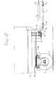
- Figure 2 shows a side view of the trailer according to the present invention.
- Figure 3 diagrammatically depicts the path followed by the pulling vehicle and the trailer in the low-speed position.
- Figure 4 diagrammatically depicts the path followed by the pulling vehicle and the trailer in the high-speed position.
- FIGS 1 and 2 show a device according to the present invention, by means of which a pulling vehicle 1 is coupled to a trailer 2.
- the trailer 2 is connected to the pulling vehicle 1 with the aid of a shaft 3 and with the aid of an assembly comprising a steering rod 4 and a steering arm 5.
- the shaft 3 is used to pull the trailer 2 and the steering rod 4 and the steering arm 5 are used to steer the front wheels 6 of the trailer 2, depending on the angular displacement of the pulling vehicle 1 with respect to the trailer 2.
- the steering arm 5 is connected to the front wheels of the trailer in such a manner that turning of the steering arm 5 with respect to the trailer 2 results in turning of the front wheels 6 of the trailer 2 with respect to the trailer 2.
- the pulling function and the steering function of the trailer are carried out independently of one another.
- a first end 31 of the shall 3 is pivotably attached to a fixed pivot point 11.
- the second end 32 of the shaft is pivotably attached to a fixed pivot point 12 on the trailer.
- a first end 41 of the steering rod 4 is pivotably attached to the pulling vehicle 1.
- this pivot point of the steering rod 4 coincides with the pivot point 11 of the shaft 3 on the pulling vehicle 1.
- This position is illustrated in Figure 1 by solid lines.
- the pivot point of the steering rod 4 on the pulling vehicle 1 can be displaced from this position, with respect to the longitudinal axis of the pulling vehicle 1, with the aid of displacement means 8, for example a pump 81, a pressure accumulator 82 and a hydraulic cylinder 83.
- This is illustrated by means of dot-dashed lines in Figure 1.
- the pivot point of the steering rod 4 moves along a path 10, for example a guide groove, which is arranged on the pulling vehicle 1.
- the second end of the steering rod 4 is pivotably coupled to the free end 51 of a control arm 5.
- the control arm 5 is pivotably attached to the trailer 2.
- the pivot point 12 of the steering arm 5 coincides with the pivot point 12 of the shaft 3 on the trailer 2.
- the path 10 is curved in such a manner that, when the shaft 3 is in line with the longitudinal axis of the pulling vehicle 1, the pivot point of the steering arm 4 on the pulling vehicle 1 can be displaced without this causing the steering arm 5 to rotate about the pivot point 12.
- This means that the path 10 describes part of an arc of a circle, the radius of the said circle corresponding to the length of the steering rod 4.
- a first pulley 25 is attached to the steering arm 5. Like the shaft 3 and the steering arm 5, the pulley 25 can rotate with respect to the trailer 2 about the pivot point 12.
- the first pulley 25 is connected to a second pulley 26 by means of a flexible component 20.
- the flexible component 20 which is used together with the pulleys may, for example, comprise a cable, a belt, a chain or any other means which could be used.
- the second pulley 26 is coupled to the front axle 7 of the trailer 2.
- the front axle 7 and the second pulley 26 can pivot with respect to the trailer 2 about the corresponding pivot point 71.
- the first pulley 25 is smaller than the second pulley 26.
- the device according to the present invention operates as follows: If the pivot point of the steering rod 4 on the pulling vehicle 1 coincides with the pivot point 11 of the shaft 3 on the pulling vehicle (solid lines in Figure 1), the angle between the steering arm 5 and the shaft 3 remains identical irrespective of the position of the vehicles 1, 2 with respect to one another. This means that the device will then perform in the same way as a steering device which is known from the prior art, the intention being for the trailer 2 to follow the route of the pulling vehicle 1. Specifically, when the pulling vehicle 1 starts to enter a bend, the shaft 3 will, at a given moment, no longer be in line with the longitudinal axis of the vehicle 1.
- This pivoting of the shaft 3 with respect to the pulling vehicle 1 will, with the aid of the steering arm 5, the pulleys 25, 26 and the flexible component 20, impart a steering signal to the front wheels 6 of the trailer 2.
- the dimensions of the pulleys 25, 26 determine the transmission ratio with which the steering signal is transmitted to the wheels 6. If the transmission ratio is equal to one, the trailer will seek to cut the bend through which the pulling vehicle has passed. If the transmission ratio is less than one, the trailer will execute a wider bend.
- the transmission ratio can therefore be used to select the way in which the trailer 2 follows. Thus the transmission ratio may, for example, be selected in such a manner that the trailer 2 follows the route of the pulling vehicle 1. Since pulleys are used to transmit the transmission ratio, the transmission ratio remains identical irrespective of the instantaneous angular displacement of the shaft 3 with respect to the pulling vehicle 1.
- the length of the shaft 3 is extended in order to increase the stability of the trailer 2.
- the same effect can be achieved, by means of the device according to the present invention, by displacing the pivot point of the steering rod 4 on the pulling vehicle 1 along the path 10.
- the said pivot point has been displaced (steering rod 4 in broken lines in Figure 1)
- there is a steering and pulling mechanism comprising four rods between the pulling vehicle I and the trailer. This is also referred to as the "high-speed position”.
- the way in which the trailer 2 follows is determined by the length of the "virtual shaft".
- the length of the virtual shaft is given by taking the distance from the point at which the continuation of the shaft 3 and the continuation of the steering rod 4, in the direction of the pulling vehicle 1, intersect one another to the pivot point 12 on the trailer 2.
- the assembly contains means for the automatic manipulation of the displacement of the pivot point as a function of the speed at which the vehicles 1, 2 are travelling.
- the said means may, for example, comprise a microprocessor (not shown) which is coupled to the hydraulic pump 81 of the assembly.
- the path 10 is designed in such a manner that the steering rod 4 can rotate about the pivot point which it has in common with the pivot arm 5 without the steering arm 5 rotating in the process, the position of the steering rod 5 can be varied without at the same time transmitting a steering signal to the wheels 6.
- the steering rod 4 can therefore be adjusted while the vehicles 1, 2 are in motion.
- the special shape of the path 10 allows the adjustment to be carried out using relatively little force.
- the device according to the present invention is used for pulling vehicles 1 and trailers 2 in which only the front axle 7 can be steered.
- the device may equally advantageously be employed for pulling vehicles 1 and trailers 2 in which the rear wheels can also be steered.
- vehicles of this nature are often equipped with a front axle and a rear axle which are able to rotate as a unit with respect to the vehicle.
- a steering rod is generally positioned in a crosswise manner between the front axle and the rear axle, which rod ensures that a rotation of the front axle to the right is converted into a rotation of the rear axle to the left.
Landscapes
- Engineering & Computer Science (AREA)
- Transportation (AREA)
- Mechanical Engineering (AREA)
- Chemical & Material Sciences (AREA)
- Combustion & Propulsion (AREA)
- Steering Control In Accordance With Driving Conditions (AREA)
- Steering-Linkage Mechanisms And Four-Wheel Steering (AREA)
Applications Claiming Priority (2)
| Application Number | Priority Date | Filing Date | Title |
|---|---|---|---|
| NL1007906 | 1997-12-24 | ||
| NL1007906A NL1007906C2 (nl) | 1997-12-24 | 1997-12-24 | Samenstel van een trekkend voertuig, een trailer en een inrichting voor het trekken en sturen van de trailer met behulp van dat trekkende voertuig en een inrichting voor het trekken en het sturen van een trailer. |
Publications (1)
| Publication Number | Publication Date |
|---|---|
| EP0925963A1 true EP0925963A1 (de) | 1999-06-30 |
Family
ID=19766260
Family Applications (1)
| Application Number | Title | Priority Date | Filing Date |
|---|---|---|---|
| EP98204450A Withdrawn EP0925963A1 (de) | 1997-12-24 | 1998-12-24 | Anhängevorrichtung zum Anschliessen eines gezogenen Fahrzeuges an ein ziehendes mit Steuerungsvorrichtung für Anhänger |
Country Status (2)
| Country | Link |
|---|---|
| EP (1) | EP0925963A1 (de) |
| NL (1) | NL1007906C2 (de) |
Cited By (5)
| Publication number | Priority date | Publication date | Assignee | Title |
|---|---|---|---|---|
| WO2000073123A1 (en) * | 1999-05-17 | 2000-12-07 | Väderstad-Verken Ab | Towing device for an agricultural apparatus |
| CN109159632A (zh) * | 2018-08-21 | 2019-01-08 | 许彦领 | 牵引连接器 |
| EP3564098A1 (de) | 2018-05-04 | 2019-11-06 | B.V. Beco | Bidirektionaler anhänger |
| WO2023105059A1 (en) * | 2021-12-10 | 2023-06-15 | Vbg Group Ab (Publ) | Trailer with improved maneuverability |
| EP4360918A1 (de) * | 2022-10-25 | 2024-05-01 | Sandvik Mining and Construction Lyon SAS | Bergbauanhänger, bergbaufahrzeug und verfahren |
Citations (6)
| Publication number | Priority date | Publication date | Assignee | Title |
|---|---|---|---|---|
| DE1941745A1 (de) * | 1968-08-22 | 1970-07-09 | Walter Clews | Vorrichtung zur Steuerung und Stabilisierung der Fahrtrichtung von Strassenfahrzeuganhaengern |
| US3807764A (en) * | 1973-02-01 | 1974-04-30 | J Link | Anti-jackknifing device |
| DE3328123A1 (de) * | 1983-08-04 | 1985-02-14 | Wackenhut, Ernst, 7270 Nagold | Lastzug mit einer lenkung fuer das anhaengerfahrzeug |
| EP0356849A2 (de) * | 1988-08-30 | 1990-03-07 | Maschinenfabrik Bernard Krone GmbH | Zentralachsanhänger |
| DE9205034U1 (de) * | 1991-04-11 | 1992-06-11 | Karl Kässbohrer Fahrzeugwerke GmbH, 7900 Ulm | Fahrzeugzug |
| WO1995004668A1 (en) | 1993-08-10 | 1995-02-16 | Keith Peter G | Apparatus for connecting tow vehicle to trailer |
-
1997
- 1997-12-24 NL NL1007906A patent/NL1007906C2/nl not_active IP Right Cessation
-
1998
- 1998-12-24 EP EP98204450A patent/EP0925963A1/de not_active Withdrawn
Patent Citations (6)
| Publication number | Priority date | Publication date | Assignee | Title |
|---|---|---|---|---|
| DE1941745A1 (de) * | 1968-08-22 | 1970-07-09 | Walter Clews | Vorrichtung zur Steuerung und Stabilisierung der Fahrtrichtung von Strassenfahrzeuganhaengern |
| US3807764A (en) * | 1973-02-01 | 1974-04-30 | J Link | Anti-jackknifing device |
| DE3328123A1 (de) * | 1983-08-04 | 1985-02-14 | Wackenhut, Ernst, 7270 Nagold | Lastzug mit einer lenkung fuer das anhaengerfahrzeug |
| EP0356849A2 (de) * | 1988-08-30 | 1990-03-07 | Maschinenfabrik Bernard Krone GmbH | Zentralachsanhänger |
| DE9205034U1 (de) * | 1991-04-11 | 1992-06-11 | Karl Kässbohrer Fahrzeugwerke GmbH, 7900 Ulm | Fahrzeugzug |
| WO1995004668A1 (en) | 1993-08-10 | 1995-02-16 | Keith Peter G | Apparatus for connecting tow vehicle to trailer |
Cited By (7)
| Publication number | Priority date | Publication date | Assignee | Title |
|---|---|---|---|---|
| WO2000073123A1 (en) * | 1999-05-17 | 2000-12-07 | Väderstad-Verken Ab | Towing device for an agricultural apparatus |
| US6517097B1 (en) | 1999-05-17 | 2003-02-11 | Vaderstad - Verken Ab | Towing device for an agricultural apparatus |
| EP3564098A1 (de) | 2018-05-04 | 2019-11-06 | B.V. Beco | Bidirektionaler anhänger |
| CN109159632A (zh) * | 2018-08-21 | 2019-01-08 | 许彦领 | 牵引连接器 |
| WO2023105059A1 (en) * | 2021-12-10 | 2023-06-15 | Vbg Group Ab (Publ) | Trailer with improved maneuverability |
| EP4360918A1 (de) * | 2022-10-25 | 2024-05-01 | Sandvik Mining and Construction Lyon SAS | Bergbauanhänger, bergbaufahrzeug und verfahren |
| WO2024088943A1 (en) * | 2022-10-25 | 2024-05-02 | Sandvik Mining And Construction Lyon Sas | Mining trailer, mining vehicle and method |
Also Published As
| Publication number | Publication date |
|---|---|
| NL1007906C2 (nl) | 1999-06-25 |
Similar Documents
| Publication | Publication Date | Title |
|---|---|---|
| KR100576792B1 (ko) | 멀티 액슬 차량용 스티어링 시스템 | |
| US4875536A (en) | Control device for operating a motor vehicle | |
| US20090250270A1 (en) | Steering and Driving Systems and Related Vehicles | |
| US6386310B2 (en) | Steering device, especially for farming tractors and similar commercial vehicles | |
| EP0678440B1 (de) | Lenkungsmesseinrichtung für Sattelzüge | |
| EP0100351B1 (de) | Fahrzeuglenkungsmechanismus | |
| JPH0372510B2 (de) | ||
| US4941671A (en) | Four-wheel steerable vehicle having a fore/aft sliding link | |
| HU193631B (en) | Multiple-axle articulated motor vehicle particularly articulated bus | |
| US5137292A (en) | All-wheel steering for motor vehicles | |
| HU189705B (en) | Device for preventing unintentional joint moving and improving the side stability on the way in the case of critical way and run conditions, mounted at the fulcrum of jointed vehicle and applicable at saddle tractors, jointed buses or vehicles connected with trailer | |
| US5013057A (en) | Method of controlling a transport means and a transport means for effecting the method | |
| DE3436596A1 (de) | Steuersystem fuer vorder- und hinterraeder | |
| EP1640247B1 (de) | Auflieger oder Anhänger mit verbesserter Lenkungsregelung | |
| CA2612954A1 (en) | Piste grooming vehicle with cable torque compensation | |
| HK1021166A (en) | Towing device for coupling a towed vehicle to a towing vehicle comprising a trailer steering device | |
| NL1007906C2 (nl) | Samenstel van een trekkend voertuig, een trailer en een inrichting voor het trekken en sturen van de trailer met behulp van dat trekkende voertuig en een inrichting voor het trekken en het sturen van een trailer. | |
| HK1047418A1 (en) | Traction apparatus of trailer | |
| JP2590012B2 (ja) | トレーラの車輪操向装置 | |
| EP1888393B1 (de) | Anhängerschleppsteuervorrichtung | |
| WO2002020333A1 (en) | Steering device for an articulated vehicle | |
| CN220721186U (zh) | 一种转向控制装置及拖车控制系统 | |
| RU2013269C1 (ru) | Система рулевого управления транспортного средства со всеми управляемыми колесами | |
| US5137291A (en) | Rear wheel steering arrangement | |
| CA1316954C (en) | Method of controlling a transport means and a transport means for effecting the method |
Legal Events
| Date | Code | Title | Description |
|---|---|---|---|
| PUAI | Public reference made under article 153(3) epc to a published international application that has entered the european phase |
Free format text: ORIGINAL CODE: 0009012 |
|
| AK | Designated contracting states |
Kind code of ref document: A1 Designated state(s): BE DE DK ES FI FR GB GR IE IT NL PT SE |
|
| AX | Request for extension of the european patent |
Free format text: AL;LT;LV;MK;RO;SI |
|
| 17P | Request for examination filed |
Effective date: 19991228 |
|
| AKX | Designation fees paid |
Free format text: BE DE DK ES FI FR GB GR IE IT LU MC NL PT SE |
|
| RBV | Designated contracting states (corrected) |
Designated state(s): BE DE DK ES FI FR GB GR IE IT LU MC |
|
| RBV | Designated contracting states (corrected) |
Designated state(s): BE DE DK ES FI FR GB GR IE IT NL PT SE |
|
| RBV | Designated contracting states (corrected) |
Designated state(s): AT BE DE DK ES FI FR GB GR IE IT NL PT SE |
|
| RBV | Designated contracting states (corrected) |
Designated state(s): BE DE DK ES FI FR GB GR IE IT NL PT SE |
|
| 17Q | First examination report despatched |
Effective date: 20020524 |
|
| GRAP | Despatch of communication of intention to grant a patent |
Free format text: ORIGINAL CODE: EPIDOSNIGR1 |
|
| STAA | Information on the status of an ep patent application or granted ep patent |
Free format text: STATUS: THE APPLICATION IS DEEMED TO BE WITHDRAWN |
|
| 18D | Application deemed to be withdrawn |
Effective date: 20050121 |
|
| REG | Reference to a national code |
Ref country code: HK Ref legal event code: WD Ref document number: 1021166 Country of ref document: HK |