EP0925985B1 - Kraftstoffeinfüllstutzen-Gehäuse mit schnappbaren Einbauring für Kraftfahrzeuge - Google Patents
Kraftstoffeinfüllstutzen-Gehäuse mit schnappbaren Einbauring für Kraftfahrzeuge Download PDFInfo
- Publication number
- EP0925985B1 EP0925985B1 EP98120738A EP98120738A EP0925985B1 EP 0925985 B1 EP0925985 B1 EP 0925985B1 EP 98120738 A EP98120738 A EP 98120738A EP 98120738 A EP98120738 A EP 98120738A EP 0925985 B1 EP0925985 B1 EP 0925985B1
- Authority
- EP
- European Patent Office
- Prior art keywords
- trim
- flange
- housing
- trim member
- body panel
- Prior art date
- Legal status (The legal status is an assumption and is not a legal conclusion. Google has not performed a legal analysis and makes no representation as to the accuracy of the status listed.)
- Expired - Lifetime
Links
- 239000000446 fuel Substances 0.000 title claims abstract description 26
- 239000000945 filler Substances 0.000 title claims abstract description 20
- 239000003973 paint Substances 0.000 claims abstract description 13
- 239000004033 plastic Substances 0.000 claims description 10
- 229920003023 plastic Polymers 0.000 claims description 10
- 230000008878 coupling Effects 0.000 claims description 7
- 238000010168 coupling process Methods 0.000 claims description 7
- 238000005859 coupling reaction Methods 0.000 claims description 7
- 238000000034 method Methods 0.000 claims description 7
- 239000012858 resilient material Substances 0.000 claims description 2
- 238000007789 sealing Methods 0.000 claims description 2
- 238000010422 painting Methods 0.000 description 6
- 239000000463 material Substances 0.000 description 4
- 238000009434 installation Methods 0.000 description 3
- 238000000465 moulding Methods 0.000 description 3
- 239000002537 cosmetic Substances 0.000 description 2
- 230000008602 contraction Effects 0.000 description 1
- 238000004070 electrodeposition Methods 0.000 description 1
- 239000002184 metal Substances 0.000 description 1
- 230000007704 transition Effects 0.000 description 1
Images


Classifications
-
- B—PERFORMING OPERATIONS; TRANSPORTING
- B60—VEHICLES IN GENERAL
- B60K—ARRANGEMENT OR MOUNTING OF PROPULSION UNITS OR OF TRANSMISSIONS IN VEHICLES; ARRANGEMENT OR MOUNTING OF PLURAL DIVERSE PRIME-MOVERS IN VEHICLES; AUXILIARY DRIVES FOR VEHICLES; INSTRUMENTATION OR DASHBOARDS FOR VEHICLES; ARRANGEMENTS IN CONNECTION WITH COOLING, AIR INTAKE, GAS EXHAUST OR FUEL SUPPLY OF PROPULSION UNITS IN VEHICLES
- B60K15/00—Arrangement in connection with fuel supply of combustion engines or other fuel consuming energy converters, e.g. fuel cells; Mounting or construction of fuel tanks
- B60K15/03—Fuel tanks
- B60K15/04—Tank inlets
-
- B—PERFORMING OPERATIONS; TRANSPORTING
- B05—SPRAYING OR ATOMISING IN GENERAL; APPLYING FLUENT MATERIALS TO SURFACES, IN GENERAL
- B05B—SPRAYING APPARATUS; ATOMISING APPARATUS; NOZZLES
- B05B12/00—Arrangements for controlling delivery; Arrangements for controlling the spray area
- B05B12/16—Arrangements for controlling delivery; Arrangements for controlling the spray area for controlling the spray area
- B05B12/40—Devices for making a normally hidden area accessible for the spray material
-
- B—PERFORMING OPERATIONS; TRANSPORTING
- B60—VEHICLES IN GENERAL
- B60K—ARRANGEMENT OR MOUNTING OF PROPULSION UNITS OR OF TRANSMISSIONS IN VEHICLES; ARRANGEMENT OR MOUNTING OF PLURAL DIVERSE PRIME-MOVERS IN VEHICLES; AUXILIARY DRIVES FOR VEHICLES; INSTRUMENTATION OR DASHBOARDS FOR VEHICLES; ARRANGEMENTS IN CONNECTION WITH COOLING, AIR INTAKE, GAS EXHAUST OR FUEL SUPPLY OF PROPULSION UNITS IN VEHICLES
- B60K15/00—Arrangement in connection with fuel supply of combustion engines or other fuel consuming energy converters, e.g. fuel cells; Mounting or construction of fuel tanks
- B60K15/03—Fuel tanks
- B60K15/04—Tank inlets
- B60K15/0406—Filler caps for fuel tanks
- B60K2015/0419—Self-sealing closure caps, e.g. that don't have to be removed manually
-
- Y—GENERAL TAGGING OF NEW TECHNOLOGICAL DEVELOPMENTS; GENERAL TAGGING OF CROSS-SECTIONAL TECHNOLOGIES SPANNING OVER SEVERAL SECTIONS OF THE IPC; TECHNICAL SUBJECTS COVERED BY FORMER USPC CROSS-REFERENCE ART COLLECTIONS [XRACs] AND DIGESTS
- Y10—TECHNICAL SUBJECTS COVERED BY FORMER USPC
- Y10T—TECHNICAL SUBJECTS COVERED BY FORMER US CLASSIFICATION
- Y10T29/00—Metal working
- Y10T29/49—Method of mechanical manufacture
- Y10T29/49826—Assembling or joining
- Y10T29/49863—Assembling or joining with prestressing of part
- Y10T29/49876—Assembling or joining with prestressing of part by snap fit
-
- Y—GENERAL TAGGING OF NEW TECHNOLOGICAL DEVELOPMENTS; GENERAL TAGGING OF CROSS-SECTIONAL TECHNOLOGIES SPANNING OVER SEVERAL SECTIONS OF THE IPC; TECHNICAL SUBJECTS COVERED BY FORMER USPC CROSS-REFERENCE ART COLLECTIONS [XRACs] AND DIGESTS
- Y10—TECHNICAL SUBJECTS COVERED BY FORMER USPC
- Y10T—TECHNICAL SUBJECTS COVERED BY FORMER US CLASSIFICATION
- Y10T29/00—Metal working
- Y10T29/49—Method of mechanical manufacture
- Y10T29/49826—Assembling or joining
- Y10T29/49885—Assembling or joining with coating before or during assembling
Definitions
- the invention relates generally to automotive fuel filler pipe housings mountable on a mounting member according to claim 1 and a method for mounting such a housing upon an automotive body panel according to claim 14.
- Such a housing is known from U.S Patent No. 5,437,491 entitled “Fuel Door Housing” issued 1 August 1991 and assigned commonly herewith. It discloses a plastic fuel filler pipe housing with a flange portion mountable in an opening of a vehicle body panel, wherein the body panel includes a recessed mounting surface disposed about the opening thereof so that a hinged door of the housing is flush with an outer surface of the body panel. A capped end portion of the fuel filler pipe extends through the housing, and is accessible upon opening the housing door.
- the earlier application EP 0 922 601 A shows an automotive fuel filler pipe housing mountable on an automotive body panel, the housing comprising a flange member having an exterior side and an interior side coupleable toward the automotive body panel; a trim member having an interior side, an exterior side, and a distal end portion; a hinge coupling the trim member to the flange member so the distal end portion of the trim member extends from the flange member; the trim member movable relative to the flange member between a first position where the distal end portion of the trim member is positioned away from the flange member, and a second position where the distal end portion of the trim member is positioned toward the flange member, whereby the interior side of the trim member is positioned away from a surface of the automotive body panel in the first position and the interior side of the trim member is positioned toward the surface of the automotive body panel in the second position.
- Other fuel filler pipe housings do not include a hinged door, but merely provide a transition between the fuel filler pipe and the body panel, leaving the fuel cap exposed.
- the housing may provide some support for the fuel filler pipe, but the capped end portion thereof is designed generally to readily break away from the housing during impact to prevent fuel leakage.
- the housing may also collect and drain small amounts of fuel spillage during refueling, and may provide some aerodynamic streamlining and cosmetic contouring continuous with the body panel, particularly in passenger vehicles where styling is paramount.
- Automotive fuel filler pipe housings are installed generally after painting the automotive body panels to ensure that the housing and portions of the automotive body panel proximate the housing accommodating opening therein are painted completely.
- the housing is suspended in a window opening of the auto body and painted therewith, then later mounted in the automotive body panel. Suspending the housing from the automotive body for painting, however, must be performed manually and is laborious. And mounting the housing on the body panel after painting poses a risk of damage to the painted finish during installation.
- the present invention is drawn generally toward advancements in the art of housings and more particularly to automotive fuel filler pipe housings.
- the housing comprises generally a flange member coupled to a body member mountable on the automotive body panel.
- a trim member is coupled to the flange member by a hinge, wherein the trim member is movable relative to the flange member between a first position away from an exterior surface of the automotive body panel and a second position toward the exterior surface of the automotive body panel, whereby the trim member is biased in one of the first and second positions.
- FIGS. 1a and 1b illustrate a housing 10 mountable on a mounting member 20, and useable for housing fuel filler pipes, not shown, in automotive body panels.
- the mounting member 20 referenced in the exemplary and preferred embodiments is thus an automotive body panel with an exterior surface 22, but is representative more generally of any mounting member.
- the housing 10 comprises generally a flange member 30, a trim member 40 and a body member 50.
- the flange member 30 is coupled to the trim member 40 by a hinge 60, and is also coupled to the body member 50 to form the housing 10, which is mountable on the automotive body panel 20.
- the flange member 30 has an exterior side 32 and an interior side 34 facing, or coupleable toward, the automotive body panel 20.
- the flange member 30 may be mounted directly on the body panel 20, or coupled thereto by the body member 50, or a combination thereof as discussed further below.
- the exemplary body member 50 has an inlet opening 51 and an outlet opening 52, wherein the body member 50 is at least partially disposable in an opening 24 of the automotive body panel 20.
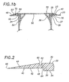
- FIG. 2 illustrates the trim member 40 having an interior side 42, an exterior side 44, and a distal end portion 46.
- the hinge 60 couples the trim member 40 and the flange member 30, and more particularly couples an inner portion 43 of the trim member 40 with an outer portion 33 the flange member 30 so the distal end portion 46 of the trim member 40 extends generally from the flange member 30.
- FIGS. 1a and 1b illustrate the trim member 40 movable relative to the flange member 30 between a first position where the distal end portion 46 of the trim member 40 is positioned generally away from the flange member 30 shown in FIG. 1a, and a second position where the distal end portion 46 of the trim member 40 is positioned generally toward the flange member 30 shown in FIG. 1b.
- the distal end portion 46 of the trim member 40 is disposed axially beyond the exterior side 32 of the flange member 30 when the trim member 40 is in the first position, and the distal end portion 46 of the trim member 40 is disposed substantially radially about the flange member 30 when the trim member is in the second position.
- FIG. 1a illustrates the housing 10 installed partially on the automotive body panel 20 with the trim member 40 in the first position so that paint may be applied to at least a portion of the exterior surface 22 of the automotive body panel 20.
- paint is applied to at least portions 23 of the automotive body panel exterior 22 subsequently coverable by the trim member 40 in the second position.
- FIG. 1b illustrates the trim member 40 moved to the second position toward the automotive body panel 20 after applying paint thereto, whereby the portions 23 of the exterior surface 22 covered by the trim member 40 are painted.
- the trim member 40 and automotive body panel 20 may thus expand and contract at different rates without exposing any unpainted areas of the automotive body panel exterior surface 22 that would otherwise be exposed during relative expansion and contraction therebetween if the automotive body panel 20 and trim member 40 were painted with the trim member in the second position.
- FIG. 4 illustrates the trim member 40 and hinge 60 both having an annular ring shape disposed about a portion of the flange member 30.
- the trim member 40 is substantially ring shaped having an oval or other closed ended shape.
- the hinge 60 does not necessarily have the same shape as the trim member 40, which may be shaped irregularly to follow the contours of the body panel 20.
- the trim member 40 is not closed ended, and may have a curved or a linear edge defined by the distal end portion 46 thereof, thereby forming a flap movable between the first and second positions discussed above.
- FIGS. 1a, 1b and 2 illustrate the hinge 60 formed partially by a first recess 62 disposed between the trim member 40 and the flange member 30 on the exterior sides thereof, and partially by a second recess 64 disposed between the trim member 40 and the flange member 30 on the interior sides thereof, whereby the trim member 40 is biased in one of the first and second positions and snaps flexibly therebetween.
- the hinge 60 in the exemplary embodiments is continuous and close ended, but in alternative embodiments the hinge may comprise a plurality of discrete components, which are not continuous.
- the hinge 60 In embodiments having open-ended trim members with a linear or curved edge defined by the distal end portion 46 thereof, the hinge 60 must generally be curved as it is defined between the flange member 30 and the trim member 40, thereby providing the snapping action required to bias the trim member in one of the first and second positions as discussed above.
- the hinge 60 is formed preferably of a flexible resilient material, whereby the trim member 40 is biased toward one of the first and second positions.
- the flange member 30, the trim member 40 and the hinge 60 are a unitary member, which may be formed of a plastic material in a molding operation. Molding the trim member 40 in one of the first and second positions relative to the flange member 30 will bias the trim member 40 in one of the first and second positions and provide the desired snap action therebetween.
- FIG. 1a illustrates the interior side 42 of the trim member 40 in the first position disposed away from an exterior surface 22 of the automotive body panel 20, and FIG. 1b illustrates the interior side 42 of the trim member 40 in the second position disposed toward the exterior surface 22 of the automotive body panel 20, whereby the trim member 40 provides a continuous interface between the flange member 30 and the automotive body panel 20.
- the bias of the trim member 40 in the second position toward the automotive body panel also provides a tight fit that conforms with body panel 20 contours without gaps or space between the trim member 40 and the body panel 20, thereby providing a high quality styled finish, which is essential in most markets, particularly the passenger motor vehicle markets.
- FIG. 1b also illustrates a sealing member 70 disposed along the interior side 42 of the trim member 40 and the exterior surface 22 of the automotive body panel 20 to provide a seal therebetween.
- FIGS. 1a and 1b illustrate the body member 50 coupled to the automotive body panel 20, and FIGS. 1a, 1b, and 3 illustrate a plurality of resilient engagement members 56 protruding from the body member 50 and disposed about the outlet opening 52 thereof.
- the plurality of resilient engagement members 56 are generally engageable with the automotive body panel 20 to couple and retain the body member 50 at least partially in the opening 24 thereof.
- the resilient engagement members 56 include a stem portion 57 formed by adjacent recesses 58 in the body member 50, and a bevelled edge 59 engageable with the opening 24 of the automotive body panel 20 to flex the stem 57 inwardly, which permits installation of the body member 50 in the opening 24 thereof.
- FIG. 1a illustrates an engagement portion 55 of the resilient engagement members 56 seated on the exterior surface 22 of the automotive body panel 20 when the body member 50 is installed in the opening 24 thereof.
- the resilient members 56 are preferably breakable under predetermined stress and strain conditions to separate the housing 10 from the automotive body panel 40 during impacts as required by governmental and industry fuel systems safety regulations and standards.
- the body member 50 and the plurality of resilient engagement members 56 are a unitary member, which is preferably formable from a plastic material in a molding operation.
- the dimensions and number of plastic material resilient members 56 may be designed to break or fail under predetermined stress and strain conditions occurring during impact with accurate predictability, which is necessary to comply with fuel system safety regulations and standards.
- FIG. 4 illustrates a plurality of curved flange portions 36 and a plurality of resilient tab members 37 protruding from the interior side 34 of the flange member 30.
- FIGS. 1a and 1b illustrate one of the curved flange members 36 disposable in a recess 54 formed on an end portion 53 of the body member 50 when the flange member 30 is coupled thereto.
- FIG. 3 illustrates a continuous recess 54 disposed in the end 53 of the body member 50, and in alternative embodiment the recess 53 may be a plurality of discrete recesses corresponding to the curved flange portions 36.
- the resilient tab members 37 of the flange member 30 are generally engageable with the opening 24 in the automotive body panel 20 to retain the flange member 30 coupled thereto and to retain the flange member 30 assembled to the body member 50.
- FIGS. 1a, 1b and 4 illustrate the resilient tab members 37 having a resilient stem 38, a bevelled surface 39 engageable with the opening 24 in the automotive body panel 20 to inwardly flex the resilient tab members 37 as the flange member 30 is disposed therethrough and possibly assembled with the body member 50, which is preferably mounted therein previously as discussed above.
- the resilient tab members 37 also include a surface portion 35 engageable with an interior side 26 of the automotive body panel 20 to retain the flange member 30 in assembly therewith and with the body member 50.
- the curved flange members 36 of the flange member 30 also prevent the resilient engagement members 56 of the body member 50 from flexing inwardly and disengaging from the automotive body panel 20.
- the body member 50 includes recesses 55 on the end portion 53 thereof to accommodate the resilient tab members 37 of the flange member 30.
Landscapes
- Engineering & Computer Science (AREA)
- Life Sciences & Earth Sciences (AREA)
- Sustainable Development (AREA)
- Sustainable Energy (AREA)
- Chemical & Material Sciences (AREA)
- Combustion & Propulsion (AREA)
- Transportation (AREA)
- Mechanical Engineering (AREA)
- Cooling, Air Intake And Gas Exhaust, And Fuel Tank Arrangements In Propulsion Units (AREA)
- Motor Or Generator Frames (AREA)
Claims (17)
- Kraftstoffeinfüllstutzen-Gehäuse für Kraftfahrzeuge, welches auf einem Befestigungselement montierbar ist, wobei das Gehäuse (10) enthält:gekennzeichnet durchein Flanschelement (30), welches eine Außenseite (32) und eine Innenseite (34) aufweist und zum Befestigungselement (20) hin kuppelbar ist;
ein Trimmelement (40), welches eine Innenseite (42), eine Außenseite (44) und einen distalen Endabschnitt (46) hat;
ein Gelenk (60), welches das Trimmelement (40) mit dem Flanschelement (30) kuppelt, so dass der distale Endabschnitt (46) des Trimmelements (40) sich vom Flanschelement (30) wegerstreckt; wobei das Trimmelement (40) relativ zum Flanschelement (30) bewegbar ist zwischen einer ersten Position, wo der distale Endabschnitt (46) des Trimmelements (40) vom Flanschelement (30) entfernt positioniert ist, und einer zweiten Position, wo der distale Endabschnitt (46) des Trimmelements (40) zum Flanschelement (30) hin positioniert ist,
wobei die Innenseite (42) des Trimmelements (40) von einer Oberfläche (22) des Befestigungselements (20) in der ersten Position entfernt positioniert ist und die Innenseite (42) des Trimmelements (40) in der zweiten Position zur Oberfläche (22) des Befestigungselements (20) hin positioniert ist;
Mittel (37) zum Kuppeln einer Innenseite (34) des Flanschelements (30) zu einer Außenfläche (22) des Befestigungselements (20) hin, wenn das Trimmelement (40) in der ersten Position ist. - Gehäuse nach Anspruch 1, wobei der distale Endabschnitt (46) des Trimmelements (40) in der ersten Position axial jenseits der Außenseite (32) des Flanschelements (30) angeordnet ist, und der distale Endabschnitt (46) des Trimmelements (40) in der zweiten Position im wesentlichen radial um das Flanschelement (30) angeordnet ist.
- Gehäuse nach Anspruch 1 oder 2, wobei das Trimmelement (40) im wesentlichen ringförmig ist und um einen Abschnitt des Flanschelements (30) angeordnet ist.
- Gehäuse nach mindestens einem der vorhergehenden Ansprüche, wobei das Flanschelement (30), das Gelenk (60) und das Trimmelement (40) aus einem einheitlichen Kunststoffelement gebildet sind.
- Gehäuse nach mindestens einem der vorhergehenden Ansprüche, wobei das Gelenk (60) teilweise durch eine erste Ausnehmung (62) zwischen dem Trimmelement (40) und dem Flanschelement (30) auf den Außenseiten (32, 44) des Flanschelements (30) und des Trimmelements (40) gebildet ist, und das Gelenk (60) teilweise durch eine zweite Ausnehmung (64) zwischen dem Trimmelement (40) und dem Flanschelement (30) auf den Innenseite (34, 42) des Flanschelements (30) und des Trimmelements( 40) gebildet ist, wobei das Trimmelement (40) zwischen der ersten Position und der zweiten Position umschnappt.
- Gehäuse nach mindestens einem der vorhergehenden Ansprüche, wobei das Gelenk (60) bogenförmig ist und aus einem flexiblen elastischen Material gebildet ist, wobei das Trimmelement (40) zu einer der ersten und zweiten Positionen hin vorgespannt ist.
- Gehäuse nach mindestens einem der vorhergehenden Ansprüche, ferner enthaltend ein Dichtungselement (70),welches längs der Innenseite (42) des Trimmelements (40) angeordnet ist.
- Gehäuse nach mindestens einem der vorhergehenden Ansprüche, ferner enthaltend ein Karosserieelement (50), welches eine Auslassöffnung (52) hat, wobei das Karosserieelement (50) mindestens teilweise in einer Öffnung des Befestigungselements (20) angeordnet ist und das Flanschelement (30) mit dem Karosserieelement (50) gekuppelt ist.
- Gehäuse nach Anspruch 8, ferner enthaltend eine Vielzahl von bogenförmigen Flanschabschnitten (36) und eine Vielzahl von elastischen Laschenelementen (37), welchen von der Innenseite (34) des Flanschelements (36) wegragen, wobei die gebogenen Flanschelemente (36) in einer Ausnehmung (54) unterbringbar sind, welche an einem Endabschnitt (53) des Karosserieelements (50) gebildet ist, wenn das Flanschelement (30) mit dem Karosserieelement (50) gekuppelt ist, und die elastischen Laschenelemente (37) mit der Öffnung (24) im Befestigungselement (20) in Eingriff bringbar sind, um das Flanschelement (30) festzuhalten, welches mit dem Karosserieelement (50) gekuppelt ist.
- Gehäuse nach Anspruch 8 oder 9, ferner enthaltend eine Vielzahl von elastischen Eingriffselementen (56), welche vom Karosserieelement (50) wegragen und um die Auslassöffnung (52) des Karosserieelements (50) angeordnet sind, wobei die Vielzahl von elastischen Eingriffselementen (56) mit dem Befestigungselement (20) in Eingriff bringbar ist, um das Karosserieelement (50) mindestens teilweise in der Öffnung (24) des Befestigungselements (20) zu halten.
- Gehäuse nach mindestens einem der vorhergehenden Ansprüche, ferner enthaltend das Befestigungselement (20) mit einer Außenseite (22), wobei die Innenseite (34) des Flanschelements (30) zu der Außenseite (22) des Befestigungselements (20) hin gekuppelt ist, das Trimmelement (40) von der Außenseite (22) des Befestigungselements (20) in der ersten Position entfernt positioniert ist, und das Trimmelement (40) in der zweiten Position zur der Außenseite (22) des Befestigungselements (20) hin positioniert ist.
- Gehäuse nach mindestens einem der vorhergehenden Ansprüche, wobei das Flanschelement (30), das Gelenk (60) und das Trimmelement (40) aus einem einheitlichen Kunststoffelement gebildet sind, und wobei das Trimmelement (40) zu einer der ersten und zweiten Position hin vorgespannt ist.
- Gehäuse nach mindesten einem der vorhergehenden Ansprüche, dadurch gekennzeichnet, dass das Befestigungselement (20) ein Kraftfahrzeug-Karosserieteil ist.
- Verfahren zum Montieren eines Kraftstoffeinfüllstutzen-Gehäuses nach Anspruch 1 an einem Kraftfahrzeug-Karosserieteil, dadurch gekennzeichnet, dass das Gehäuse (10) das Gelenkelement (60) hat, welches das Flanschelement (30) mit dem Trimmelement (40) verbindet, welches den distalen Endabschnitt (46) aufweist, wobei das Trimmelement (40) relativ zum Flanschelement (30) zwischen der ersten Position, wo der distale Endabschnitt (46) des Trimmelements (40) axial jenseits der Außenseite (32) des Flanschelements (30) angeordnet ist, und der zweiten Position, wo der distale Endabschnitt (46) des Trimmelements (40) im wesentlichen radial vom Flanschelement (30) angeordnet ist, bewegbar ist, wobei das Verfahren enthält:Bewegen des Trimmelements (40) in die erste Position;Kuppeln einer Innenseite (34) des Flanschelements (30) zu einer Außenseite (22) des Kraftfahrzeug-Karosserieteiles (20) hin, wenn das Trimmelement (40) in der ersten Position ist, wobei die Innenseite (42) des Trimmelements (40) von der Außenseite (22) des Kraftfahrzeug-Karosserieteiles (20) entfernt positioniert ist; undBewegen des Trimmelements (40) in die zweite Position, nachdem das Flanschelement (30) mit der Außenseite (22) des Kraftfahrzeug-Karosserieteiles (20) gekuppelt ist, wobei die Innenseite (42) des Trimmelements (40) zur Außenseite (22) des Kraftfahrzeug-Karosserieteiles (20) hin positioniert ist.
- Verfahren nach Anspruch 14, ferner enthaltend das Auftragen von Farbe auf mindestens einen Abschnitt der Außenseite (22) des Kraftfahrzeug-Karosserieteiles (20), wenn das Trimmelement (40) in der ersten Position ist, wobei die Farbe auf mindestens einen Abschnitt (23) der Außenseite (22) des Kraftfahrzeug-Karosserieteiles (20) aufgetragen wird, welcher durch das Trimmelement (40) in der zweiten Position bedeckbar ist, und Bewegen des Trimmelements (40) in die zweite Position zum Kraftfahrzeug-Karosserieteil (20) hin, nachdem Farbe aufgetragen wurde.
- Verfahren nach Anspruch 14 oder 15, ferner enthaltend Kuppeln eines Karosserieelements (50) mindestens teilweise in einer Öffnung (24) des Kraftfahrzeug-Karosserieteiles (20) vor dem Kuppeln des Flanschelements (30) mit der Außenseite (22) des Kraftfahrzeug-Karosserieteiles (20), und dann Kuppeln des Flanschelements (30) mit dem Karosserieelement (50).
- Verfahren nach Anspruch 16, ferner enthaltend Festhalten des Karosserieelements (50), welches an das Kraftfahrzeug-Karosserieteil (20) gekuppelt ist, mit dem Flanschelement (30).
Applications Claiming Priority (2)
| Application Number | Priority Date | Filing Date | Title |
|---|---|---|---|
| US991215 | 1997-12-16 | ||
| US08/991,215 US6026554A (en) | 1997-12-16 | 1997-12-16 | Automotive fuel filler pipe housing with snap-over trim ring |
Publications (2)
| Publication Number | Publication Date |
|---|---|
| EP0925985A1 EP0925985A1 (de) | 1999-06-30 |
| EP0925985B1 true EP0925985B1 (de) | 2003-03-05 |
Family
ID=25536983
Family Applications (1)
| Application Number | Title | Priority Date | Filing Date |
|---|---|---|---|
| EP98120738A Expired - Lifetime EP0925985B1 (de) | 1997-12-16 | 1998-11-02 | Kraftstoffeinfüllstutzen-Gehäuse mit schnappbaren Einbauring für Kraftfahrzeuge |
Country Status (6)
| Country | Link |
|---|---|
| US (1) | US6026554A (de) |
| EP (1) | EP0925985B1 (de) |
| AT (1) | ATE233667T1 (de) |
| BR (1) | BR9805438A (de) |
| DE (1) | DE69811840T2 (de) |
| ES (1) | ES2194267T3 (de) |
Families Citing this family (3)
| Publication number | Priority date | Publication date | Assignee | Title |
|---|---|---|---|---|
| US6508501B1 (en) | 2001-08-21 | 2003-01-21 | Adac Plastics Inc. | Fuel filler door assembly |
| DE102009056569A1 (de) * | 2009-12-01 | 2011-06-09 | Dr. Ing. H.C. F. Porsche Aktiengesellschaft | Fronthaube |
| US9855901B1 (en) | 2016-08-24 | 2018-01-02 | Ford Global Technologies Llc | Flange for exterior ornamentation |
Citations (2)
| Publication number | Priority date | Publication date | Assignee | Title |
|---|---|---|---|---|
| US5437491A (en) * | 1994-04-07 | 1995-08-01 | Illinois Tool Works Inc. | Fuel door housing |
| EP0922601A1 (de) * | 1997-12-12 | 1999-06-16 | Illinois Tool Works Inc. | Kugelventil für Kraftstoffeinfüllstutzen eines Kraftfahrzeuges |
Family Cites Families (13)
| Publication number | Priority date | Publication date | Assignee | Title |
|---|---|---|---|---|
| US3334779A (en) * | 1965-09-09 | 1967-08-08 | Richard N Smith | Closure for automotive fuel tanks and the like |
| US3616960A (en) * | 1970-05-20 | 1971-11-02 | Gen Motors Corp | Filler pipe closure for pressurized fuel tank |
| IT1024633B (it) * | 1974-10-18 | 1978-07-20 | Farelli Mario | Bocchettone per serbatoi di carburante, negli autoveicoli in genere, complanare rispetto al piano del la scocca e mezzi per il suo rapido montaggio in sede di impiego |
| GB2026452B (en) * | 1978-07-28 | 1983-05-05 | Neiman Diffusion | Conversion ring for fuel tank mouths |
| US4653660A (en) * | 1984-10-17 | 1987-03-31 | Shaw James R | Insert for a fuel tank inlet and a method of installing the insert |
| US5090105A (en) * | 1986-03-14 | 1992-02-25 | Chrysler Corporation | Modular vehicle construction and assembly method |
| US5090760A (en) * | 1990-01-29 | 1992-02-25 | Wheeler Basil W | Break-away gas fill guard |
| DE556347T1 (de) * | 1991-02-23 | 1993-11-04 | Donald Murray Sutton Surrey Western | Verfahren zum abdcken von fensterdichtungen. |
| US5118155A (en) * | 1991-04-08 | 1992-06-02 | Molmec, Inc. | Fuel filler pocket |
| DE4242228C2 (de) * | 1992-12-15 | 1995-12-07 | Webasto Karosseriesysteme | Tankverschlußsystem für einen Kraftstoffbehälter eines Kraftfahrzeuges |
| US5441168A (en) * | 1994-03-21 | 1995-08-15 | Carlini; Anthony J. | Protective seal ring for motorcycle fuel filler neck |
| SE503109C2 (sv) * | 1994-08-11 | 1996-03-25 | Sten Corfitsen | Adapter för automatisk tankning av fordon |
| US5560175A (en) * | 1995-09-13 | 1996-10-01 | Chrysler Corporation | Vehicle body molding with folding flange |
-
1997
- 1997-12-16 US US08/991,215 patent/US6026554A/en not_active Expired - Lifetime
-
1998
- 1998-11-02 DE DE69811840T patent/DE69811840T2/de not_active Expired - Fee Related
- 1998-11-02 ES ES98120738T patent/ES2194267T3/es not_active Expired - Lifetime
- 1998-11-02 AT AT98120738T patent/ATE233667T1/de not_active IP Right Cessation
- 1998-11-02 EP EP98120738A patent/EP0925985B1/de not_active Expired - Lifetime
- 1998-12-09 BR BR9805438-4A patent/BR9805438A/pt not_active IP Right Cessation
Patent Citations (2)
| Publication number | Priority date | Publication date | Assignee | Title |
|---|---|---|---|---|
| US5437491A (en) * | 1994-04-07 | 1995-08-01 | Illinois Tool Works Inc. | Fuel door housing |
| EP0922601A1 (de) * | 1997-12-12 | 1999-06-16 | Illinois Tool Works Inc. | Kugelventil für Kraftstoffeinfüllstutzen eines Kraftfahrzeuges |
Also Published As
| Publication number | Publication date |
|---|---|
| ATE233667T1 (de) | 2003-03-15 |
| US6026554A (en) | 2000-02-22 |
| EP0925985A1 (de) | 1999-06-30 |
| BR9805438A (pt) | 1999-11-03 |
| ES2194267T3 (es) | 2003-11-16 |
| DE69811840T2 (de) | 2003-09-04 |
| DE69811840D1 (de) | 2003-04-10 |
Similar Documents
| Publication | Publication Date | Title |
|---|---|---|
| EP0861748B1 (de) | In einer Richtung wirkendes, klappenartiges Fahrzeugentlüftungsventil | |
| EP0792766B1 (de) | Mit Aussenwand versehenes,geformtes Rahmenmodul | |
| CN106499272B (zh) | 用于装配汽车套件的汽车设备以及包括这样的汽车设备的汽车套件 | |
| US8979169B2 (en) | Device for fastening a vehicle interior trim panel | |
| CN107627972B (zh) | 机动车辆密封结构用柱密封护圈 | |
| CA2149573C (en) | Flexible sealing unit for movable windows | |
| EP0922601B1 (de) | Kugelventil für Kraftstoffeinfüllstutzen eines Kraftfahrzeuges | |
| US7784799B2 (en) | Apparatus and method for sealing surfaces | |
| US6026554A (en) | Automotive fuel filler pipe housing with snap-over trim ring | |
| FR2505475B1 (fr) | Boitier de montage d'un echangeur de chaleur, en particulier pour une installation de chauffage de l'habitacle d'un vehicule automobile | |
| EP1574381A2 (de) | Verschlusskappe für Füllstutzen eines Treibstofftanks | |
| US7226107B1 (en) | Method and apparatus for sunvisor attachment | |
| CN1107602C (zh) | 汽车门上孔洞的封闭部件 | |
| EP1285844A2 (de) | Struktur und Verfahren für die Befestigung eines Aussenteils | |
| KR100317020B1 (ko) | 디프로스터덕트의 설치구조 | |
| US5786067A (en) | In situ automotive gasket and method of making same | |
| EP3444171A1 (de) | Verschlussstopfen zum verschliessen einer öffnung und anordnung mit einem verschlussstopfen | |
| US20040134295A1 (en) | Engine compartment breather boot | |
| KR100333872B1 (ko) | 자동차의 윈드실드 지지 구조 | |
| US5069499A (en) | Motor vehicle hatchback and a method for producing same | |
| US12434639B2 (en) | Grommet and method of installation on a vehicle | |
| EP1857372B1 (de) | Flüssigkeitsladevorrichtung | |
| EP4417492A1 (de) | Verkleidungssystem und verfahren zur herstellung | |
| US20250196595A1 (en) | Vehicle door including sensor attachment scheme | |
| US20040256475A1 (en) | Thermostat lip seal |
Legal Events
| Date | Code | Title | Description |
|---|---|---|---|
| PUAI | Public reference made under article 153(3) epc to a published international application that has entered the european phase |
Free format text: ORIGINAL CODE: 0009012 |
|
| AK | Designated contracting states |
Kind code of ref document: A1 Designated state(s): AT BE DE ES FR GB IT NL |
|
| AX | Request for extension of the european patent |
Free format text: AL;LT;LV;MK;RO;SI |
|
| 17P | Request for examination filed |
Effective date: 19990804 |
|
| AKX | Designation fees paid |
Free format text: AT BE DE ES FR GB IT NL |
|
| 17Q | First examination report despatched |
Effective date: 20010608 |
|
| GRAG | Despatch of communication of intention to grant |
Free format text: ORIGINAL CODE: EPIDOS AGRA |
|
| GRAG | Despatch of communication of intention to grant |
Free format text: ORIGINAL CODE: EPIDOS AGRA |
|
| GRAG | Despatch of communication of intention to grant |
Free format text: ORIGINAL CODE: EPIDOS AGRA |
|
| GRAH | Despatch of communication of intention to grant a patent |
Free format text: ORIGINAL CODE: EPIDOS IGRA |
|
| GRAH | Despatch of communication of intention to grant a patent |
Free format text: ORIGINAL CODE: EPIDOS IGRA |
|
| GRAA | (expected) grant |
Free format text: ORIGINAL CODE: 0009210 |
|
| AK | Designated contracting states |
Designated state(s): AT BE DE ES FR GB IT NL |
|
| PG25 | Lapsed in a contracting state [announced via postgrant information from national office to epo] |
Ref country code: NL Free format text: LAPSE BECAUSE OF FAILURE TO SUBMIT A TRANSLATION OF THE DESCRIPTION OR TO PAY THE FEE WITHIN THE PRESCRIBED TIME-LIMIT Effective date: 20030305 Ref country code: BE Free format text: LAPSE BECAUSE OF FAILURE TO SUBMIT A TRANSLATION OF THE DESCRIPTION OR TO PAY THE FEE WITHIN THE PRESCRIBED TIME-LIMIT Effective date: 20030305 Ref country code: AT Free format text: LAPSE BECAUSE OF FAILURE TO SUBMIT A TRANSLATION OF THE DESCRIPTION OR TO PAY THE FEE WITHIN THE PRESCRIBED TIME-LIMIT Effective date: 20030305 |
|
| REG | Reference to a national code |
Ref country code: GB Ref legal event code: FG4D |
|
| REF | Corresponds to: |
Ref document number: 69811840 Country of ref document: DE Date of ref document: 20030410 Kind code of ref document: P |
|
| NLV1 | Nl: lapsed or annulled due to failure to fulfill the requirements of art. 29p and 29m of the patents act | ||
| REG | Reference to a national code |
Ref country code: ES Ref legal event code: FG2A Ref document number: 2194267 Country of ref document: ES Kind code of ref document: T3 |
|
| ET | Fr: translation filed | ||
| PLBE | No opposition filed within time limit |
Free format text: ORIGINAL CODE: 0009261 |
|
| STAA | Information on the status of an ep patent application or granted ep patent |
Free format text: STATUS: NO OPPOSITION FILED WITHIN TIME LIMIT |
|
| 26N | No opposition filed |
Effective date: 20031208 |
|
| PGFP | Annual fee paid to national office [announced via postgrant information from national office to epo] |
Ref country code: GB Payment date: 20051026 Year of fee payment: 8 |
|
| PGFP | Annual fee paid to national office [announced via postgrant information from national office to epo] |
Ref country code: FR Payment date: 20051117 Year of fee payment: 8 |
|
| PGFP | Annual fee paid to national office [announced via postgrant information from national office to epo] |
Ref country code: ES Payment date: 20051124 Year of fee payment: 8 |
|
| PGFP | Annual fee paid to national office [announced via postgrant information from national office to epo] |
Ref country code: DE Payment date: 20060102 Year of fee payment: 8 |
|
| PGFP | Annual fee paid to national office [announced via postgrant information from national office to epo] |
Ref country code: IT Payment date: 20061130 Year of fee payment: 9 |
|
| PG25 | Lapsed in a contracting state [announced via postgrant information from national office to epo] |
Ref country code: DE Free format text: LAPSE BECAUSE OF NON-PAYMENT OF DUE FEES Effective date: 20070601 |
|
| GBPC | Gb: european patent ceased through non-payment of renewal fee |
Effective date: 20061102 |
|
| REG | Reference to a national code |
Ref country code: FR Ref legal event code: ST Effective date: 20070731 |
|
| PG25 | Lapsed in a contracting state [announced via postgrant information from national office to epo] |
Ref country code: GB Free format text: LAPSE BECAUSE OF NON-PAYMENT OF DUE FEES Effective date: 20061102 |
|
| REG | Reference to a national code |
Ref country code: ES Ref legal event code: FD2A Effective date: 20061103 |
|
| PG25 | Lapsed in a contracting state [announced via postgrant information from national office to epo] |
Ref country code: FR Free format text: LAPSE BECAUSE OF NON-PAYMENT OF DUE FEES Effective date: 20061130 Ref country code: ES Free format text: LAPSE BECAUSE OF NON-PAYMENT OF DUE FEES Effective date: 20061103 |
|
| PG25 | Lapsed in a contracting state [announced via postgrant information from national office to epo] |
Ref country code: IT Free format text: LAPSE BECAUSE OF NON-PAYMENT OF DUE FEES Effective date: 20071102 |