EP0926049A2 - System und Verfahren zur Kontrolle des Zusammendrückens von Fahrzeuglängsträgern - Google Patents
System und Verfahren zur Kontrolle des Zusammendrückens von Fahrzeuglängsträgern Download PDFInfo
- Publication number
- EP0926049A2 EP0926049A2 EP98203990A EP98203990A EP0926049A2 EP 0926049 A2 EP0926049 A2 EP 0926049A2 EP 98203990 A EP98203990 A EP 98203990A EP 98203990 A EP98203990 A EP 98203990A EP 0926049 A2 EP0926049 A2 EP 0926049A2
- Authority
- EP
- European Patent Office
- Prior art keywords
- crush
- vehicle
- impact
- rail
- actuator
- Prior art date
- Legal status (The legal status is an assumption and is not a legal conclusion. Google has not performed a legal analysis and makes no representation as to the accuracy of the status listed.)
- Granted
Links
- 238000000034 method Methods 0.000 title claims description 19
- 239000003999 initiator Substances 0.000 claims abstract description 44
- 239000002131 composite material Substances 0.000 claims abstract description 18
- 230000004044 response Effects 0.000 claims description 5
- 230000000977 initiatory effect Effects 0.000 claims description 3
- 230000002093 peripheral effect Effects 0.000 claims description 2
- 239000000463 material Substances 0.000 description 6
- 238000012360 testing method Methods 0.000 description 6
- 230000000750 progressive effect Effects 0.000 description 5
- 239000000835 fiber Substances 0.000 description 4
- 230000009467 reduction Effects 0.000 description 4
- 229920000271 Kevlar® Polymers 0.000 description 3
- 230000004888 barrier function Effects 0.000 description 3
- 230000000694 effects Effects 0.000 description 3
- 239000011521 glass Substances 0.000 description 3
- 239000004761 kevlar Substances 0.000 description 3
- 230000002787 reinforcement Effects 0.000 description 3
- OKTJSMMVPCPJKN-UHFFFAOYSA-N Carbon Chemical compound [C] OKTJSMMVPCPJKN-UHFFFAOYSA-N 0.000 description 2
- 229920000049 Carbon (fiber) Polymers 0.000 description 2
- 230000005540 biological transmission Effects 0.000 description 2
- 229910052799 carbon Inorganic materials 0.000 description 2
- 239000004917 carbon fiber Substances 0.000 description 2
- 238000010276 construction Methods 0.000 description 2
- 239000003733 fiber-reinforced composite Substances 0.000 description 2
- 238000012423 maintenance Methods 0.000 description 2
- 238000004519 manufacturing process Methods 0.000 description 2
- VNWKTOKETHGBQD-UHFFFAOYSA-N methane Chemical compound C VNWKTOKETHGBQD-UHFFFAOYSA-N 0.000 description 2
- 238000010134 structural reaction injection moulding Methods 0.000 description 2
- 239000004593 Epoxy Substances 0.000 description 1
- 229910000831 Steel Inorganic materials 0.000 description 1
- 229910000746 Structural steel Inorganic materials 0.000 description 1
- 239000000853 adhesive Substances 0.000 description 1
- 230000001070 adhesive effect Effects 0.000 description 1
- 230000003466 anti-cipated effect Effects 0.000 description 1
- 230000000454 anti-cipatory effect Effects 0.000 description 1
- 230000007423 decrease Effects 0.000 description 1
- 239000004744 fabric Substances 0.000 description 1
- 239000011159 matrix material Substances 0.000 description 1
- 239000002184 metal Substances 0.000 description 1
- 238000012986 modification Methods 0.000 description 1
- 230000004048 modification Effects 0.000 description 1
- 229920000728 polyester Polymers 0.000 description 1
- 230000003014 reinforcing effect Effects 0.000 description 1
- 229920005989 resin Polymers 0.000 description 1
- 239000011347 resin Substances 0.000 description 1
- 230000002441 reversible effect Effects 0.000 description 1
- 239000002356 single layer Substances 0.000 description 1
- 239000007787 solid Substances 0.000 description 1
- 239000010959 steel Substances 0.000 description 1
- 229920005992 thermoplastic resin Polymers 0.000 description 1
- 229920001187 thermosetting polymer Polymers 0.000 description 1
- 238000001721 transfer moulding Methods 0.000 description 1
Images



Classifications
-
- B—PERFORMING OPERATIONS; TRANSPORTING
- B62—LAND VEHICLES FOR TRAVELLING OTHERWISE THAN ON RAILS
- B62D—MOTOR VEHICLES; TRAILERS
- B62D21/00—Understructures, i.e. chassis frame on which a vehicle body may be mounted
- B62D21/15—Understructures, i.e. chassis frame on which a vehicle body may be mounted having impact absorbing means, e.g. a frame designed to permanently or temporarily change shape or dimension upon impact with another body
- B62D21/152—Front or rear frames
-
- B—PERFORMING OPERATIONS; TRANSPORTING
- B60—VEHICLES IN GENERAL
- B60R—VEHICLES, VEHICLE FITTINGS, OR VEHICLE PARTS, NOT OTHERWISE PROVIDED FOR
- B60R19/00—Wheel guards; Radiator guards, e.g. grilles; Obstruction removers; Fittings damping bouncing force in collisions
- B60R2019/007—Means for adjusting or regulating the crash absorption capacity of the vehicle, e.g. when detecting an impending collision
-
- B—PERFORMING OPERATIONS; TRANSPORTING
- B60—VEHICLES IN GENERAL
- B60R—VEHICLES, VEHICLE FITTINGS, OR VEHICLE PARTS, NOT OTHERWISE PROVIDED FOR
- B60R21/00—Arrangements or fittings on vehicles for protecting or preventing injuries to occupants or pedestrians in case of accidents or other traffic risks
- B60R2021/0002—Type of accident
- B60R2021/0009—Oblique collision
Definitions
- This invention relates generally to longitudinal vehicle structural rails subject to crush forces in the event of full frontal and offset frontal vehicle impacts and, more particularly, to a control system and method for varying the crush force of fiber reinforced composite tubular frame rails as a function of the type of impact.
- all three load paths are functional to absorb and dissipate the vehicle's energy as it rapidly decelerates. Testing has shown that the outer load paths together dissipate 40%- 70% of the vehicle's energy, while the central path dissipates the remainder.
- the side longitudinal rails are designed to dissipate energy by deforming at force levels that will provide passenger compartment decelerations consistent with occupant safety requirements.
- the first technique links the crush responses of the two side load paths through the use of robust cross-car members, such as tie-bars, radiator support brackets, and the engine cradle, in combination with the use of more rigid joints between the longitudinal and cross-car members.
- the second technique reinforces the passenger compartment to help maintain its integrity.
- Example test specimens comprised composite 20" hollow tubes having a cross-section 31 ⁇ 2" square with 0.1" thick walls and 1 ⁇ 2" outside radiused corners. Materials tested include fiber reinforcements of Kevlar, E-glass, carbon and hybrid combinations.
- this invention features a crush control system for a vehicle subject to full frontal and offset frontal impacts which has longitudinal composite side frame rails each having a peripheral wall, which system controls the crush force of each rail as a function of the type of vehicle impact.
- the crush control system has a crush controller normally spaced from the front end of each rail that includes a body insertable into the rail, a plurality of crush initiators normally retracted into the body and an actuator operable to deploy the initiators outwardly of the body in a position to initiate controlled crushing at a reduced force level of the frame wall upon vehicle impact.
- An impact sensor for each actuator is mounted on the side of the vehicle opposite its actuator and is operable when sensing a vehicle impact on its side of the vehicle to operate its actuator.
- this invention provides a method of selectively controlling the crush forces generated by a pair of spaced vehicle composite structural side rails in the event of a vehicle full frontal impact or an offset frontal impact, comprising the steps of
- this method includes the steps of
- the crush initiators comprise a plurality of spaced knife members pivotally mounted on the body in a position normally inwardly of the body and pivotable outwardly of the body by the actuator.
- the crush initiators comprise a plurality of circumferentially-spaced wedge members, and mounting means normally mounting the wedge members inwardly of the body for movement radially outwardly of the body by the actuator.
- the mounting means are engageable by the vehicle structure upon impact to maintain the knife or wedge members outwardly of the body throughout the duration of crushing.
- an automotive vehicle 20 includes pairs of upper and lower structural side rails 22a, 22b, 24a, 24b (only the upper rails 22a and 24a are illustrated). These side rails are made of a composite material and have a generally square cross-section.
- Composite materials in the context of this invention comprises fiber-reinforced composite material structures formed of a single or multiple layers or plies of reinforcing fabric that is made of oriented or randomly arranged fibers of such materials as carbon, Kevlar, glass, and hybrids thereof, with the fibers embedded in a solid matrix of a thermosetting or thermoplastic resin material such as epoxy or polyester. These materials can be manufactured by many methods, such as SRIM (structural reaction injection molding) or RTM (resin transfer molding) techniques.
- These composite structural frame members are usually of hollow tubular form having a square or rectangular cross-section, although other shapes can be used.
- Vehicle 20 mounts the usual bumper 26 on supports 28.
- a cross-body member 30 mounts crush controllers 32a, 32b, 34a & 34b spaced in front of the respective side rails 22a, 22b, 24a & 24b.
- the crush controllers are identical and, thus, only one, crush controller 32a, will be described in detail.
- a crush controller body includes an optional mounting flange 36 for attaching components, such as the bumper beam 26, to the front end of the assembly, a rail guide 38, and a rear wedge guide 40.
- the crush controllers could alternatively be mounted directly to bumper 26 using flanges 36, or can be inserted into the front ends of the rails 22a, 22b, 24a, 24b and attached by an adhesive between the rails and the rail guide 38.
- Wedge guide 40 mounts a wedge 42, having four circumferentially-spaced angled guide slots 44, for sliding axial movement in a guide slot 46.
- Four crush initiators 48 each having a clevis 50, that mounts a pin 52 received in a guide slot 44 of wedge 42, and a crush head 54 having a radiused contact surface 55.
- Rail guide 38 is connected to and spaced from rear wedge guide 40 by a central support 56 which creates a radial crush initiator slide passage 58.
- a solenoid-operated actuator 60 is secured to the rear of rear wedge guide 40 and to wedges 42 via an arm 64.
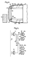
- the inactive position of crush controller 32a is illustrated in Fig. 2.
- arm 64 Upon actuation of actuator 60, arm 64 extends to project wedge 42 through openings 66 in the rear face 68 of rail guide 38.
- This forward movement of guide slots 44 forces pins 52 and their attached crush initiators 48 radially outward in slide passage 58 to the Fig. 3 position, overlying the walls of the front end of rail 22a. Crush initiators 48 will remain in this extended position so long as wedges 42 remain in their projected position.
- Selectively controlling operation of the crush controller 32a will selectively determine the amount of crush force that rail 22a can generate when engaged in an impact. If crush initiators 48 are deployed to their operative Fig. 3 position, impact with another vehicle or a barrier 70 will engage contact faces 55 with the ends of the walls of rail 22a. This will cause rail 22a to crush in a controlled manner. In one example, rail 22a will generate 20 kN of crush force with crush initiators 48 deployed as in Fig. 3. However, crush controller 32a will have no effect if the crush initiators 48 are retracted into their inoperative Fig. 2 position. Impact will merely telescope crush controller 32a into rail 22a, which will then crush in an uncontrolled manner, generating double, or 40 kN of crush force. Rail crush forces in this example are thus halved when crush initiators 48 are deployed in operative position.
- the side rails are designed so that the rails on either side of the vehicle generate sufficient crush force, with the crush initiators inoperative, to, with the central load path, dissipate the total pre-impact energy of the vehicle.
- the crush controllers must be inoperative in an offset frontal impact so that the rails on one side of the vehicle can generate the required high crush force.
- the crush controllers must be operative in a full frontal impact, so that only half the required crush force is generated by the rails on each side of the vehicle. Otherwise, the total rail crush force would be double the required amount and unacceptable passenger compartment deceleration levels might be reached.
- an impact sensor system is provided to control operation of the crash controllers 32a, 32b, 34a, 34b.
- an impact sensor 72 is provided on the side of the vehicle 20 in front of crush controllers 32a, 32b, and a like sensor 74 is provided on the side of the vehicle in front of crush controllers 34a, 34b.
- a circuit, comprising lines 76, 78, 80 connects impact sensor 72 to the actuators of crush controllers 34a, 34b.
- Lines 82, 84, 86 connect impact sensor 74 to the actuators of crush controllers 32a, 32b.
- sensor 72 Upon sensing an impact, sensor 72 will cause the actuators to deploy the crush initiators 48 of both crush actuators 34a and 34b.
- sensor 74 will cause the actuators to deploy the crush initiators 48 of both crush actuators 32a and 32b.
- the sensor that controls a particular crush controller is located on the opposite side of the vehicle from the crush controller and its associated rail.
- Sensors 72 and 74 are preferably contact switches. These and other reactive type switches, such as proximity switches, or inertial devices, such as ball-in-sleeve accelerometers, could also be used. These reactive devices would function upon initial contact and would be able to readily discriminate between low-energy and severe collisions. Anticipatory devices, such as microwave radar, vision systems, and infrared LED devices could also be used, although operation of the crush controller actuators would have to be reversible in the event that an anticipated impact was avoided or involved no rail crush.
- the crush control system operates in the following manner, using as an example an impact where a total of 80 kN of crush force must be generated by the rails.
- an offset frontal impact on the left side of vehicle 20 with barrier 70 will be detected by sensor 74, which will cause the actuators of crush controllers 32a and 32b on the other side of vehicle 20 from it to deploy their crush initiators 48.
- sensor 72 senses no impact, crush controllers 34a and 34b will remain inoperative. This will enable rails 34a and 34b to deform in an uncontrolled manner.
- Each rail will dissipate 40 kN of crush force, together totaling the entire 80 kN. Since rails 32a and 32b are not impacted, the deployment of crush controllers 32a and 32b has no effect.
- a symmetrical response would occur for an offset frontal impact on the other (right) side of the vehicle.
- Crush controllers 32a and 32b would remain inoperative and rails 22a and 22b would generate all of the required 80 kN of rail crush force, while sensor 72 would cause crush controllers 34a and 34b to become operative, to no effect.
- a full frontal impact with a barrier 75 will be detected by both impact sensors 72 and 74, which will cause the actuators of all crush controllers 32a, 32b, 34a and 34b to deploy the crush initiators 48.
- Each rail will now experience controlled crushing, dissipating 20 kN, or only half the crush force as uncontrolled crushing. However, since twice the number of rails is now impacted, the same total rail crush force of 80 kN is dissipated, 20 kN per rail.
- a crush controller 86 has a body 88 that is insertable into the side rail 22a.
- Body 88 has four circumferentially-spaced slots 90 and mounts a solenoid actuator 92 that has a normally extended arm 94.
- Arm 94 mounts a bracket 96 with four circumferentially-spaced pins 98 that are received in open-end slots 99 of a bellcrank 100.
- a bracket 102 carries pins 104 that each pivotally mounts one of the bellcranks 100 that have knife cutters 106 on their distal ends at slots 90.
- Fig. 11 illustrates crush controller 86 in inoperative position, with actuator arm 94 extended to retract knife blades 106 inwardly of body 88.
- actuator arm 94 extended to retract knife blades 106 inwardly of body 88.
- an impact would merely telescope crush controller 86 into rail 22a, which will then crush in an uncontrolled manner, as in the Figs. 1 - 3 embodiment.
- Operation of actuator 92 to retract arm 94 pivots bellcranks 100 to deploy knife cutters 106 to their Figs. 10 and 12 operative position overlying the end of the walls of rail 22a.
- impact will drive knives 106 into the rail end, beginning a controlled crush.
- the bumper 26 or other structure will impact the actuator 60 to keep the arm 94 retracted, assuring that knife cutters 106 remain deployed and sustain the controlled crush.
- FIG. 13 An alternative embodiment of an impact sensor system is shown in Fig. 13. In contrast to the Fig. 5 embodiment, this embodiment has all crush controllers normally in operative position with their crush initiators 48 deployed in operative position. The same primary control circuitry is used as in the Fig. 5 embodiment, with lines 76, 78 and 80 connecting sensor 72 with the actuators of opposite-side crush controllers 34a and 34b, and lines 82, 84 and 86 connecting sensor 74 to the actuators of opposite-side crush initiators 32a and 32b.
- This embodiment features a secondary circuit which connects sensor 72 with same-side crush controllers via lines 112, 114 and 116, while lines 118, 120 and 122 connect sensor 74 with same-side crush controllers 34a and 34b.
- both sensors are connected to all four crush controllers via the primary and secondary circuits.
- signals sent through the primary circuit maintain the crush initiators in operative position, while signals sent through the secondary circuit cause the actuators to move the crush initiators to inoperative position.
- sensor 74 will signal the actuators of crush controllers 34a and 34b via lines 118, 120 and 122 in the secondary circuit to move to inoperative position, enabling rails 24a and 24b to achieve uncontrolled crush.
- Circuit logic has the primary circuit signals override the secondary circuit signals when both signals are received.
- the actuators of crush controllers 32a and 32b will receive a primary circuit signal to maintain operational position from sensor 74, and a secondary circuit signal to move to inoperative position from sensor 72.
- the primary signal circuit overrides the secondary circuit signal and crush controllers will remain in their operative position to initiate a controlled crush of rails 22a and 22b.
- the same sequence occurs on the other side of vehicle 20, so that all crush controllers remain operative in the event of a full frontal impact.
- Both embodiments provide a controlled crush of impacted side rails in a full frontal impact, while enabling the uncontrolled crush of the impacted rails in an offset frontal impact. This enables a vehicle to generate the proper level of crush force and better manage the crush intrusion and passenger compartment deceleration in either impact event.
Landscapes
- Engineering & Computer Science (AREA)
- Chemical & Material Sciences (AREA)
- Combustion & Propulsion (AREA)
- Transportation (AREA)
- Mechanical Engineering (AREA)
- Body Structure For Vehicles (AREA)
- Vibration Dampers (AREA)
Applications Claiming Priority (2)
| Application Number | Priority Date | Filing Date | Title |
|---|---|---|---|
| US994508 | 1997-12-19 | ||
| US08/994,508 US6019419A (en) | 1997-12-19 | 1997-12-19 | Vehicle rail crush control system and method |
Publications (3)
| Publication Number | Publication Date |
|---|---|
| EP0926049A2 true EP0926049A2 (de) | 1999-06-30 |
| EP0926049A3 EP0926049A3 (de) | 2001-03-14 |
| EP0926049B1 EP0926049B1 (de) | 2002-05-15 |
Family
ID=25540731
Family Applications (1)
| Application Number | Title | Priority Date | Filing Date |
|---|---|---|---|
| EP98203990A Expired - Lifetime EP0926049B1 (de) | 1997-12-19 | 1998-11-25 | System und Verfahren zur Kontrolle des Zusammendrückens von Fahrzeuglängsträgern |
Country Status (3)
| Country | Link |
|---|---|
| US (1) | US6019419A (de) |
| EP (1) | EP0926049B1 (de) |
| DE (1) | DE69805389D1 (de) |
Cited By (8)
| Publication number | Priority date | Publication date | Assignee | Title |
|---|---|---|---|---|
| WO2001026952A1 (en) * | 1999-10-09 | 2001-04-19 | Ford Global Technologies, Inc. | Vehicle with multiple crash modes |
| EP1437290A3 (de) * | 2003-01-07 | 2004-10-27 | HONDA MOTOR CO., Ltd. | Fahrzeugrahmen mit Vorrichtung zum Ausüben einer Kraft |
| FR2874368A1 (fr) * | 2004-08-20 | 2006-02-24 | Renault Sas | Structure pour vehicule automobile et vehicule equipe d'une telle structure |
| EP1683709A1 (de) * | 2005-01-24 | 2006-07-26 | Renault s.a.s. | Verbindungselement zwischen einem Hilfsrahmen und einem energieabsorbierenden Element |
| FR2919560A1 (fr) * | 2007-08-03 | 2009-02-06 | Hydro Aluminium Alunord Soc Ci | Structure de caisse de vehicule automobile et vehicule comportant une telle structure de caisse |
| FR2928318A1 (fr) * | 2008-03-07 | 2009-09-11 | Peugeot Citroen Automobiles Sa | Ensemble d'absorption d'energie et vehicule comportant un tel ensemble |
| WO2012007209A1 (de) * | 2010-07-16 | 2012-01-19 | Robert Bosch Gmbh | Crashstruktur mit einstellbarer steifigkeit für ein deformationselement für ein fahrzeug |
| KR102255541B1 (ko) * | 2020-02-05 | 2021-05-24 | 현대위아 주식회사 | 차량용 충격흡수 장치 |
Families Citing this family (21)
| Publication number | Priority date | Publication date | Assignee | Title |
|---|---|---|---|---|
| SE507768C2 (sv) * | 1996-11-21 | 1998-07-13 | Volvo Ab | Frontstruktur i ett fordon |
| US6739624B2 (en) | 1997-10-16 | 2004-05-25 | Magna International Inc. | Frame assembly for a motor vehicle |
| US6193303B1 (en) * | 1998-04-03 | 2001-02-27 | Honda Giken Kogyo Kabushiki Kaisha | Control device for controlling rigidity and deformation of car body |
| SE522126C2 (sv) * | 2000-12-08 | 2004-01-13 | Volvo Lastvagnar Ab | Anordning för att försvaga en konstruktion |
| US6879897B2 (en) | 2002-10-19 | 2005-04-12 | General Motors Corporation | Method and system for achieving constant average impact deceleration independent of vehicle load |
| US6994350B2 (en) * | 2003-03-28 | 2006-02-07 | General Motors Corporation | Crush zone and method for introducing crush zone into vehicle structure |
| US7509191B2 (en) * | 2003-09-12 | 2009-03-24 | Honda Motor Co., Ltd. | Frame deformation control apparatus |
| JP4217141B2 (ja) | 2003-10-23 | 2009-01-28 | 本田技研工業株式会社 | 車体剛性調整装置 |
| JP4268011B2 (ja) * | 2003-10-23 | 2009-05-27 | 本田技研工業株式会社 | 車体剛性調整装置 |
| US7243981B2 (en) * | 2005-06-03 | 2007-07-17 | Daimlerchrysler Corporation | Vehicle body deformation control assembly |
| US7347465B2 (en) * | 2006-08-22 | 2008-03-25 | Ford Global Technologies, Llc | Retractable automotive front end with wedge locking members |
| US7900984B2 (en) * | 2009-02-20 | 2011-03-08 | GM Global Technology Operations LLC | Interface joint for motor vehicle |
| KR101022784B1 (ko) * | 2009-08-19 | 2011-03-17 | 한국과학기술원 | 길이 가변형 차량용 충격 흡수 장치 |
| US8113555B2 (en) * | 2009-08-21 | 2012-02-14 | Ford Global Technologies, Llc | Vehicle impact mitigation system |
| US8660756B2 (en) * | 2010-01-11 | 2014-02-25 | Honda Motor Co., Ltd. | Collision mitigation system |
| US8246091B1 (en) | 2011-08-10 | 2012-08-21 | Ford Global Technologies, Llc | Inertia-locking reactive bumper for motor vehicle |
| US8267445B1 (en) | 2012-02-06 | 2012-09-18 | Ford Global Technologies, Llc | Inertia-locking reactive bumper for motor vehicle |
| US8827356B2 (en) * | 2012-04-18 | 2014-09-09 | Ford Global Technologies, Llc | Inflatable side rail deflector apparatus for small offset collisions |
| US9283924B1 (en) * | 2014-09-23 | 2016-03-15 | Ford Global Technologies, Llc | Hinge for a vehicle hood |
| PL229944B1 (pl) * | 2015-03-05 | 2018-09-28 | Axtone Spolka Akcyjna | Urządzenie pochłaniające energię uderzeń |
| US9821755B2 (en) | 2016-01-29 | 2017-11-21 | Ford Global Technologies, Llc | Hinge for a vehicle hood |
Family Cites Families (19)
| Publication number | Priority date | Publication date | Assignee | Title |
|---|---|---|---|---|
| NL134701C (de) * | 1965-11-12 | |||
| DE2120075A1 (de) * | 1971-04-24 | 1972-11-09 | Volkswagenwerk Ag, 3180 Wolfsburg | Auslöseeinrichtung für eine Sicherheitsvorrichtung |
| US3831997A (en) * | 1973-03-22 | 1974-08-27 | Ford Motor Co | Controlled collapse vehicle front end structure |
| US3893726A (en) * | 1974-04-01 | 1975-07-08 | Raymond Lee Organization Inc | Shock absorber vehicle bumper |
| US4346795A (en) * | 1980-06-23 | 1982-08-31 | Harvey Hubbell Incorporated | Energy absorbing assembly |
| US4742899A (en) * | 1985-05-13 | 1988-05-10 | Ford Motor Company | Fiber reinforced tubular component |
| US5351791A (en) * | 1990-05-18 | 1994-10-04 | Nachum Rosenzweig | Device and method for absorbing impact energy |
| DE4028164A1 (de) * | 1990-07-17 | 1992-01-23 | Schneider Gesenkschmiede | Pralldaempfer |
| JP2983704B2 (ja) * | 1990-08-09 | 1999-11-29 | マツダ株式会社 | 車両の衝突センサ取り付け構造 |
| JP2991311B2 (ja) * | 1991-03-30 | 1999-12-20 | マツダ株式会社 | 車体後部構造 |
| US5441301A (en) * | 1991-07-09 | 1995-08-15 | Automotive Technologies International, Inc. | Crush sensing vehicle crash sensor |
| JPH05139242A (ja) * | 1991-11-19 | 1993-06-08 | Toyota Motor Corp | 車体の前部構造 |
| DE4345550C5 (de) * | 1992-07-08 | 2008-06-12 | Suspa Holding Gmbh | Pralldämpfer |
| DE4240237C2 (de) * | 1992-11-30 | 1995-02-16 | Gkn Automotive Ag | Stauchrohr |
| JPH07242153A (ja) * | 1994-03-04 | 1995-09-19 | Tokai Rika Co Ltd | クラッシュセンサ |
| US5460421A (en) * | 1994-05-31 | 1995-10-24 | Chrysler Corporation | Active impact column |
| US5431445A (en) * | 1994-11-28 | 1995-07-11 | Ford Motor Company | Asymmetrical beam structure for a vehicle |
| US5498045A (en) * | 1994-12-14 | 1996-03-12 | General Motors Corporation | Blow molded bumper beam and U-bolt attachment |
| US5544716A (en) * | 1995-06-22 | 1996-08-13 | Automotive Systems Laboratory, Inc. | Dual, independent sensor vehicle impact detectin system |
-
1997
- 1997-12-19 US US08/994,508 patent/US6019419A/en not_active Expired - Lifetime
-
1998
- 1998-11-25 EP EP98203990A patent/EP0926049B1/de not_active Expired - Lifetime
- 1998-11-25 DE DE69805389T patent/DE69805389D1/de not_active Expired - Lifetime
Non-Patent Citations (1)
| Title |
|---|
| None |
Cited By (13)
| Publication number | Priority date | Publication date | Assignee | Title |
|---|---|---|---|---|
| WO2001026952A1 (en) * | 1999-10-09 | 2001-04-19 | Ford Global Technologies, Inc. | Vehicle with multiple crash modes |
| EP1437290A3 (de) * | 2003-01-07 | 2004-10-27 | HONDA MOTOR CO., Ltd. | Fahrzeugrahmen mit Vorrichtung zum Ausüben einer Kraft |
| US6966602B2 (en) | 2003-01-07 | 2005-11-22 | Honda Motor Co., Ltd. | Body frame of vehicle, employing load imposing device |
| FR2874368A1 (fr) * | 2004-08-20 | 2006-02-24 | Renault Sas | Structure pour vehicule automobile et vehicule equipe d'une telle structure |
| WO2006021733A1 (fr) * | 2004-08-20 | 2006-03-02 | Renault S.A.S. | Structure pour vehicule automobile et vehicule equipe d'une telle structure |
| EP1683709A1 (de) * | 2005-01-24 | 2006-07-26 | Renault s.a.s. | Verbindungselement zwischen einem Hilfsrahmen und einem energieabsorbierenden Element |
| FR2881098A1 (fr) * | 2005-01-24 | 2006-07-28 | Renault Sas | Element de liaison entre un berceau et un element d'absorption de choc |
| FR2919560A1 (fr) * | 2007-08-03 | 2009-02-06 | Hydro Aluminium Alunord Soc Ci | Structure de caisse de vehicule automobile et vehicule comportant une telle structure de caisse |
| EP2022682A1 (de) * | 2007-08-03 | 2009-02-11 | Hydro Aluminium Alunord | Karosseriestruktur eines Kraftfahrzeugs und eine solche Karosseriestruktur umfassendes Kraftfahrzeug |
| FR2928318A1 (fr) * | 2008-03-07 | 2009-09-11 | Peugeot Citroen Automobiles Sa | Ensemble d'absorption d'energie et vehicule comportant un tel ensemble |
| WO2012007209A1 (de) * | 2010-07-16 | 2012-01-19 | Robert Bosch Gmbh | Crashstruktur mit einstellbarer steifigkeit für ein deformationselement für ein fahrzeug |
| CN102971185A (zh) * | 2010-07-16 | 2013-03-13 | 罗伯特·博世有限公司 | 用于车辆的变形元件的具有可调节的刚度的碰撞结构 |
| KR102255541B1 (ko) * | 2020-02-05 | 2021-05-24 | 현대위아 주식회사 | 차량용 충격흡수 장치 |
Also Published As
| Publication number | Publication date |
|---|---|
| EP0926049B1 (de) | 2002-05-15 |
| EP0926049A3 (de) | 2001-03-14 |
| US6019419A (en) | 2000-02-01 |
| DE69805389D1 (de) | 2002-06-20 |
Similar Documents
| Publication | Publication Date | Title |
|---|---|---|
| EP0926049B1 (de) | System und Verfahren zur Kontrolle des Zusammendrückens von Fahrzeuglängsträgern | |
| EP2143962B1 (de) | Verbindungsvorrichtung in einem Kraftfahrzeug und Steuerverfahren dafür | |
| DE102016203579B4 (de) | Airbagsystem für ein Fahrzeug | |
| CN101992738B (zh) | 车辆碰撞缓解系统 | |
| CN107804261B (zh) | 具有至少一个延伸部的安全气囊 | |
| US5167421A (en) | Safety seat equipped in automobile | |
| US6224131B1 (en) | Reactive seat system | |
| KR102869245B1 (ko) | 자동차용 스위블 시트의 에어백 지지 장치 | |
| EP3594776B1 (de) | Pedalanordnung für ein kraftfahrzeug | |
| US11794594B2 (en) | Electric-vehicle battery restraint | |
| US7438151B2 (en) | Method for limiting damages in the event of a partially overlapping frontal collision, and motor vehicle comprising a corresponding device | |
| CN107539251B (zh) | 保险杠总成 | |
| EP1339597B1 (de) | Anordnung zur schwächung einer konstruktion | |
| JP2006504563A (ja) | 分離ユニットの形態の乗員室を備えた自動車 | |
| EP4112390A1 (de) | System zur expansion von kraftfahrzeugteilen zur aufpralldämpfung im falle einer drohenden kollision | |
| JP4501521B2 (ja) | 車両用衝突衝撃制御装置 | |
| US11945295B2 (en) | Electric-vehicle battery restraint | |
| EP2543572B1 (de) | Kraftfahrzeugsicherheitsvorrichtung | |
| DE102007030995B4 (de) | Steuergerät zur Ansteuerung einer Aktuatorik für einen Personenschutz für ein Fahrzeug, Vorrichtung zum Personenschutz für ein Fahrzeug und Verfahren zur Ansteuerung einer Aktuatorik für einen Personenschutz für ein Fahrzeug | |
| US10093258B2 (en) | Arrangement for absorbing kinetic energy | |
| DE10224831A1 (de) | Kraftfahrzeug und Verfahren zur Reduzierung der Belastung von Insassen eines Kraftfahrzeugs bei einem Zusammenstoss mit einem Hindernis | |
| US10723340B2 (en) | Actuator for moving a brake booster during a collision | |
| DE102011108915A1 (de) | Rückhaltevorrichtung für ein Kraftfahrzeug | |
| US11702023B2 (en) | Deployable plate for rearward-facing seat | |
| JP2008222174A (ja) | 車両用安全装置 |
Legal Events
| Date | Code | Title | Description |
|---|---|---|---|
| PUAI | Public reference made under article 153(3) epc to a published international application that has entered the european phase |
Free format text: ORIGINAL CODE: 0009012 |
|
| AK | Designated contracting states |
Kind code of ref document: A2 Designated state(s): DE FR GB |
|
| AX | Request for extension of the european patent |
Free format text: AL;LT;LV;MK;RO;SI |
|
| PUAL | Search report despatched |
Free format text: ORIGINAL CODE: 0009013 |
|
| AK | Designated contracting states |
Kind code of ref document: A3 Designated state(s): AT BE CH CY DE DK ES FI FR GB GR IE IT LI LU MC NL PT SE |
|
| AX | Request for extension of the european patent |
Free format text: AL;LT;LV;MK;RO;SI |
|
| 17P | Request for examination filed |
Effective date: 20010510 |
|
| GRAG | Despatch of communication of intention to grant |
Free format text: ORIGINAL CODE: EPIDOS AGRA |
|
| 17Q | First examination report despatched |
Effective date: 20010831 |
|
| GRAG | Despatch of communication of intention to grant |
Free format text: ORIGINAL CODE: EPIDOS AGRA |
|
| GRAH | Despatch of communication of intention to grant a patent |
Free format text: ORIGINAL CODE: EPIDOS IGRA |
|
| AKX | Designation fees paid |
Free format text: DE FR GB |
|
| GRAH | Despatch of communication of intention to grant a patent |
Free format text: ORIGINAL CODE: EPIDOS IGRA |
|
| GRAA | (expected) grant |
Free format text: ORIGINAL CODE: 0009210 |
|
| RIN1 | Information on inventor provided before grant (corrected) |
Inventor name: JONES, GARY LEE Inventor name: BROWNE, ALAN LAMPE |
|
| AK | Designated contracting states |
Kind code of ref document: B1 Designated state(s): DE FR GB |
|
| PG25 | Lapsed in a contracting state [announced via postgrant information from national office to epo] |
Ref country code: FR Free format text: LAPSE BECAUSE OF FAILURE TO SUBMIT A TRANSLATION OF THE DESCRIPTION OR TO PAY THE FEE WITHIN THE PRESCRIBED TIME-LIMIT Effective date: 20020515 |
|
| REG | Reference to a national code |
Ref country code: GB Ref legal event code: FG4D |
|
| REF | Corresponds to: |
Ref document number: 69805389 Country of ref document: DE Date of ref document: 20020620 |
|
| PG25 | Lapsed in a contracting state [announced via postgrant information from national office to epo] |
Ref country code: DE Free format text: LAPSE BECAUSE OF FAILURE TO SUBMIT A TRANSLATION OF THE DESCRIPTION OR TO PAY THE FEE WITHIN THE PRESCRIBED TIME-LIMIT Effective date: 20020817 |
|
| PG25 | Lapsed in a contracting state [announced via postgrant information from national office to epo] |
Ref country code: GB Free format text: LAPSE BECAUSE OF NON-PAYMENT OF DUE FEES Effective date: 20021125 |
|
| EN | Fr: translation not filed | ||
| PLBE | No opposition filed within time limit |
Free format text: ORIGINAL CODE: 0009261 |
|
| STAA | Information on the status of an ep patent application or granted ep patent |
Free format text: STATUS: NO OPPOSITION FILED WITHIN TIME LIMIT |
|
| 26N | No opposition filed |
Effective date: 20030218 |
|
| GBPC | Gb: european patent ceased through non-payment of renewal fee |