EP0926056A2 - Bremsvorrichtung für ein Fahrzeug, insbesondere ein Tretauto - Google Patents
Bremsvorrichtung für ein Fahrzeug, insbesondere ein Tretauto Download PDFInfo
- Publication number
- EP0926056A2 EP0926056A2 EP98204299A EP98204299A EP0926056A2 EP 0926056 A2 EP0926056 A2 EP 0926056A2 EP 98204299 A EP98204299 A EP 98204299A EP 98204299 A EP98204299 A EP 98204299A EP 0926056 A2 EP0926056 A2 EP 0926056A2
- Authority
- EP
- European Patent Office
- Prior art keywords
- brake
- brake lever
- axis
- wheel
- braking device
- Prior art date
- Legal status (The legal status is an assumption and is not a legal conclusion. Google has not performed a legal analysis and makes no representation as to the accuracy of the status listed.)
- Withdrawn
Links
- 230000008878 coupling Effects 0.000 claims abstract description 13
- 238000010168 coupling process Methods 0.000 claims abstract description 13
- 238000005859 coupling reaction Methods 0.000 claims abstract description 13
- 238000004804 winding Methods 0.000 description 3
- NLYAJNPCOHFWQQ-UHFFFAOYSA-N kaolin Chemical group O.O.O=[Al]O[Si](=O)O[Si](=O)O[Al]=O NLYAJNPCOHFWQQ-UHFFFAOYSA-N 0.000 description 1
Images


Classifications
-
- B—PERFORMING OPERATIONS; TRANSPORTING
- B62—LAND VEHICLES FOR TRAVELLING OTHERWISE THAN ON RAILS
- B62K—CYCLES; CYCLE FRAMES; CYCLE STEERING DEVICES; RIDER-OPERATED TERMINAL CONTROLS SPECIALLY ADAPTED FOR CYCLES; CYCLE AXLE SUSPENSIONS; CYCLE SIDE-CARS, FORECARS, OR THE LIKE
- B62K23/00—Rider-operated controls specially adapted for cycles, i.e. means for initiating control operations, e.g. levers, grips
-
- B—PERFORMING OPERATIONS; TRANSPORTING
- B60—VEHICLES IN GENERAL
- B60T—VEHICLE BRAKE CONTROL SYSTEMS OR PARTS THEREOF; BRAKE CONTROL SYSTEMS OR PARTS THEREOF, IN GENERAL; ARRANGEMENT OF BRAKING ELEMENTS ON VEHICLES IN GENERAL; PORTABLE DEVICES FOR PREVENTING UNWANTED MOVEMENT OF VEHICLES; VEHICLE MODIFICATIONS TO FACILITATE COOLING OF BRAKES
- B60T1/00—Arrangements of braking elements, i.e. of those parts where braking effect occurs specially for vehicles
- B60T1/02—Arrangements of braking elements, i.e. of those parts where braking effect occurs specially for vehicles acting by retarding wheels
- B60T1/04—Arrangements of braking elements, i.e. of those parts where braking effect occurs specially for vehicles acting by retarding wheels acting directly on tread
-
- B—PERFORMING OPERATIONS; TRANSPORTING
- B60—VEHICLES IN GENERAL
- B60T—VEHICLE BRAKE CONTROL SYSTEMS OR PARTS THEREOF; BRAKE CONTROL SYSTEMS OR PARTS THEREOF, IN GENERAL; ARRANGEMENT OF BRAKING ELEMENTS ON VEHICLES IN GENERAL; PORTABLE DEVICES FOR PREVENTING UNWANTED MOVEMENT OF VEHICLES; VEHICLE MODIFICATIONS TO FACILITATE COOLING OF BRAKES
- B60T7/00—Brake-action initiating means
- B60T7/02—Brake-action initiating means for personal initiation
- B60T7/08—Brake-action initiating means for personal initiation hand actuated
-
- B—PERFORMING OPERATIONS; TRANSPORTING
- B62—LAND VEHICLES FOR TRAVELLING OTHERWISE THAN ON RAILS
- B62K—CYCLES; CYCLE FRAMES; CYCLE STEERING DEVICES; RIDER-OPERATED TERMINAL CONTROLS SPECIALLY ADAPTED FOR CYCLES; CYCLE AXLE SUSPENSIONS; CYCLE SIDE-CARS, FORECARS, OR THE LIKE
- B62K5/00—Cycles with handlebars, equipped with three or more main road wheels
-
- B—PERFORMING OPERATIONS; TRANSPORTING
- B62—LAND VEHICLES FOR TRAVELLING OTHERWISE THAN ON RAILS
- B62K—CYCLES; CYCLE FRAMES; CYCLE STEERING DEVICES; RIDER-OPERATED TERMINAL CONTROLS SPECIALLY ADAPTED FOR CYCLES; CYCLE AXLE SUSPENSIONS; CYCLE SIDE-CARS, FORECARS, OR THE LIKE
- B62K9/00—Children's cycles
-
- B—PERFORMING OPERATIONS; TRANSPORTING
- B62—LAND VEHICLES FOR TRAVELLING OTHERWISE THAN ON RAILS
- B62L—BRAKES SPECIALLY ADAPTED FOR CYCLES
- B62L1/00—Brakes; Arrangements thereof
- B62L1/02—Brakes; Arrangements thereof in which cycle wheels are engaged by brake elements
Definitions
- the invention relates to a braking device for a vehicle, especially a pedal car.
- a disadvantage of this known pedal car is that the brake lever is quite wide protrudes upwards. When transporting the pedal car to wholesale and retail the steering wheel and the seat of the pedal car are not yet assembled, so that the brake lever the most protruding bottom part. By the outstanding brake lever is also a lot of transport space for transport of the pedal car necessary.
- Another disadvantage is that the well-known pedal car has no locking device, which makes the pedal car, for example, on a inclined road surface could drive by itself.
- a braking device for a vehicle especially a pedal car
- which brake device is achieved manually with the help a brake lever can be operated and directly on the tire of a wheel of the Vehicle can attack
- the braking device having means around the brake lever to be able to put in a first stand and a second stand, in which first level the braking device can be operated to brake the wheel, and in which second state the braking device locks the wheel.
- a separable coupling is provided, which with is connected to the brake lever, with which the brake lever is in the first state a swiveling brake shoe is to be coupled. From the first stand can the brake lever is then pulled up to the brake shoe against the Press tires to be able to brake. Due to the separable coupling from To decouple the brake shoe, the brake lever can be brought to a standstill, in which he no longer stands out in terms of a pedal car without steering and seat.
- the brake shoe has a Pivot axis connected, which pivot axis with a mainly parallel axis of rotation for the brake lever is connected.
- the swivel axis is the brake shoe from the first stand against the tire pressed, the brake lever not rotating with respect to its axis of rotation.
- By the decoupling of the separable coupling is the brake lever from the first stand rotatable around its axis of rotation.
- the separable coupling is preferably in the second position from the pivot axis uncoupled so that the brake lever can be turned so far that a lower part the braking device presses against the tire to lock it.
- the brake lever is from a resilient bracket for coupling provided the pivot axis of the brake shoe, so that the brake lever with some Force to or from the swivel shoe is to be uncoupled without screws or something like that is necessary.
- the clip is preferably a coil spring which has one end on the Brake lever is hooked, and at the other end a locking hook for Has coupling to the pivot axis, wherein the spring is preferably a Has wire thickness of 2 to 3 millimeters.
- the brake lever is from a rotary bush to Provide rotation about the axis of rotation, which rotary bushing of a cam, the in the first stand has a stop against the frame of the vehicle is so that the brake lever has a fixed position in the first position.
- the weight the brake lever keeps the cam pressed against the frame.
- the cam is positioned in such a way that this in the second state a stop against the connection between the Has pivot axis and the axis of rotation. This positioning enables the In the second position, do not turn the brake lever further with regard to its axis of rotation.
- the cam has a thickness such that the brake shoe is the wheel locked when the cam is in the second position between the frame and the Connection between the pivot axis and the axis of rotation is blocked.
- the cam between the frame and the connection between the Swivel axis and the axis of rotation is locked, the brake lever can not turn itself back around the axis of rotation, and in that at the same time the Cam has a suitable thickness, the pivot axis is pivoted so far that the brake shoe presses on the tire and the wheel locks.
- the braking device is fixed and the vehicle is locked in its parking position.
- the pivot axis for the brake shoe is included an opposite brake shoe connected for an opposite wheel, so that the brake lever brakes on both rear wheels at the same time, to achieve even braking.
- the invention also relates to a vehicle, in particular a pedal car, from a braking device as described above.
- Figure 1 shows schematically a pedal car with a braking device according to the invention.
- Figure 2 schematically shows a perspective view of the braking device according to the invention and part of the frame of the pedal car.
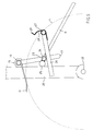
- Figure 3 shows the braking device according to Figure 2 in side view in the first Was standing.
- Figure 4 shows the braking device according to Figure 3 in the braking position.
- FIG. 5 shows the braking device according to FIG. 2 in the second, locked position.
- FIG. 1 shows a conventional pedal car 1 with a frame 2, front wheels 3, Rear wheels 4, a seat 5, a control 6, pedals 7 for driving the Rear wheels 4 using a chain 8, a brake lever 10 and a brake shoe 11.
- the brake shoe 11 is connected to a by means of a connecting device second brake shoe (not visible) connected to the other rear wheel.
- the Braking device according to the invention is not shown in Figure 1.
- Figure 2 shows the braking device according to the invention.
- Part of the Frame 2 on which a vertical support 20, 21 is arranged at both ends are.
- the axis of rotation 22 is the two rear wheels.
- the two brake shoes 11, 12 for the rear wheels are respectively connected to a pivot axis 13, 14 which is rotatable in the pivot points arranged on the vertical supports 20, 21 in the form of Nuts 15, 16 are added.
- the pivot axes 13, 14 are so good like parts 17, 19 connected at right angles, which in turn are connected by a Connecting part 18 are connected. With the help of the implemented connecting rod 13, 17, 18, 19, 14 are the brake shoes 11, 12 simultaneously twisted to brake on the rear wheels (not shown).
- a rod end or axis of rotation 23 is arranged on the converted part 17, which runs parallel to the pivot axis 13.
- a rotary bushing 24 is arranged, which is connected to the brake lever 10.
- a rod 26 is arranged against the rotary bushing 24 and the brake lever 10, which is perpendicular to the pivot axis 13.
- the rod 26 has a bent one Part 27, which runs parallel to the pivot axis 13 and through Pulling the brake lever 10 come to rest against the pivot axis 13 can.
- the bent part 27 is provided by a winding spring 28 which with one end is hooked around the rod 26 against the coil spring 28 turn to fix, and the other end to a locking hook 29th is formed, which can hook over the pivot axis 13.
- a cam 25 is against the rotary bushing 24 and the rod 26 are arranged and form a stop against the support 20.
- Figure 3 shows the brake device in side view in its first state, in which the braking device is ready for use as a brake.
- the locking hook 29 is hooked on the pivot axis 13, whereby the brake lever 10 on the Rod 26 is coupled to the brake shoe 11.
- the brake lever 10 cannot rotate around the axis of rotation 23 rotate.
- the entire braking device can now only around the pivot axis 13 rotate, and by the weight of the protruding brake lever 10 Cam 25 pressed against the vertical support 20.
- the Brake shoe 11 present at a distance above the wheel 4 by a Dash line is reproduced.
- the brake lever 10 In order to brake, the brake lever 10 is raised by the driver of the pedal car drawn, as shown in Figure 4.
- the bent part 27 with the Winding spring 28 is against the when the brake lever 10 is pulled up Swivel axis 13 pressed so that the brake lever 10 is still not in terms the axis of rotation 23 can rotate. Rotation only takes place around the Swivel axis 13 instead, and the brake shoe 11 is pressed against the wheel 4.
- the brake lever does not protrude upwards, then the brake lever is released the stand according to Figure 3 pressed down with force, whereby the locking hook 29 upwards against the spring force of the winding spring 28 is pressed and forced over the pivot axis 13, after which the Brake lever 10 can freely rotate around the axis of rotation 23.
- the brake lever 10 can then brought to a not so prominent position, whereby the pedal car is transported in a box that is as small as possible can be.
- Figure 5 shows the braking device after the locking hook 29 from the Pivot axis 13 has been uncoupled, and wherein the brake lever 10 in the second state is set to the wheel 4 with the help of the brake shoe 11 lock.
- the brake lever 10 is as far as possible around the axis of rotation 23 rotated until the cam 25 stops against the converted rod part 17th has on the pivot axis 13.
- the cam is so far round that Rotation axis 23 rotated that its anchor point against the vertical support 20th lies on the support 20 above the vertical from the axis of the axis of rotation 23.
- the Cam is therefore between the frame 20 and the converted rod part 17th locked, in that the cam 20 has such a thickness that in this second state of the brake shoe 11 presses on the tire of the wheel 4.
- the brake lever 10 can not turn around the axis of rotation 23 and the pedal car is in locked his parking space.
- the brake lever 10 In order to lock the wheel, the brake lever 10 must move freely around the axis of rotation 23 rotatable position can be forced into the second, locked position to force the brake lever 10 down with additional force against the Spring force of the brake shoe 11 on the tire of the wheel 4, causing the cam 25 along the support 20 to the locked position as shown in Figure 5 forced becomes.
- the brake lever 10 In order to unlock the wheel, the brake lever 10 must be pulled up with force to the cam 25 against the force of the brake shoe 11 on the wheel 4th to force down from its locked position, after which the brake lever 10 again freely rotatable around the axis of rotation 23 and the brake shoe 11 no longer pressed on the wheel.
Landscapes
- Engineering & Computer Science (AREA)
- Mechanical Engineering (AREA)
- Transportation (AREA)
- Braking Elements And Transmission Devices (AREA)
- Braking Arrangements (AREA)
- Mechanical Control Devices (AREA)
- Handcart (AREA)
Abstract
Description
Claims (11)
- Bremsvorrichtung für ein Fahrzeug, insbesondere ein Tretauto, welche Bremsvorrichtung manuell mit Hilfe eines Bremshebels zu bedienen ist und direkt auf den Reifen eines Rads des Fahrzeugs angreifen kann, wobei die Bremsvorrichtung Mittel hat um den Bremshebel in einen ersten Stand und einen zweiten Stand setzen zu können, in welchem ersten Stand die Bremsvorrichtung bedienbar ist, um das Rad abzubremsen, und in welchem zweiten Stand die Bremsvorrichtung das Rad verriegelt.
- Bremsvorrichtung gemäß Anspruch 1, wobei der Bremshebel mit einer trennbaren Kopplung verbunden ist, welche Kopplung in dem ersten Stand an einen schwenkbaren Bremsschuh gekoppelt ist, der durch das Anziehen des Bremshebels schwenkt und auf den Reifen drückt.
- Bremsvorrichtung gemäß Anspruch 2, wobei der Bremsschuh mit einer Schwenkachse verbunden ist, welche Schwenkachse mit einer damit hauptsächlich parallel verlaufenden Drehachse für den Bremshebel verbunden ist, wobei vorzugsweise die trennbare Kopplung in dem zweiten Stand von der Schwenkachse entkuppelt ist, damit ein Teil der Bremsvorrichtung in diesem zweiten Stand auf den Reifen drückt, um das Rad zu verriegeln.
- Bremsvorrichtung gemäß Anspruch 3, wobei der Bremshebel von einer federnden Klammer zur Kopplung an die Schwenkachse des Bremschuhs versehen ist.
- Bremsvorrichtung gemäß Anspruch 4, wobei die Klammer eine Wicklungsfeder ist, die mit einem Ende an dem Bremshebel angehakt ist und die beim anderen Ende einen Riegelhaken für Kopplung an die Schwenkachse besitzt, wobei vorzugsweise die Feder eine Drahtdicke von 2 bis 3 Millimeter hat.
- Bremsvorrichtung gemäß Anspruch 3, 4 oder 5, wobei der Bremshebel von einer Drehbuchse zur Drehung um die Drehachse versehen ist, welche Drehbuhse von einem Nocken, der in dem ersten Stand einen Anschlag gegen den Rahmen des Fahrzeuges hat, versehen ist.
- Bremsvorrichtung gemäß Anspruch 5, wobei der Nocken derart positioniert ist, daß dieser im zweiten Stand einen Anschlag gegen die Verbindung zwischen der Schwenkachse und der Drehachse hat, wobei vorzugsweise der Nocken eine derartige Dicke hat, daß im zweiten Stand der Nocken zwischen dem Rahmen und der Verbindung zwischen der Schwenkachse und der Drehachse gesperrt ist und daß gleichzeitig der Bremsschuh auf den Rad drückt, um den Rad zu verriegeln.
- Bremsvorrichtung gemäß einem der Ansprüche 3 bis einschließlich 7, wobei die Schwenkachse für den Bremsschuh mit einem gegenüberliegenden Bremsschuh für ein gegenüberliegendes Rad verbunden ist.
- Fahrzeug, im besonderen ein Tretauto, von einer Bremsvorrichtung gemäß einem der vorabgehenden Ansprüche versehen.
- Bremse für ein Fahrzeug, im besonderen ein Tretauto, von einem Bremshebel für Hand bedienung versehen, welche Bremse von einer trennbaren Kopplung um den Bremshebel mit einem Bremsschuh zu koppeln versehen ist, um bremsen zu können, und um den Bremshebel vom Bremsschuh zu entkuppeln, um das Fahrzeug mit Hilfe von dem Bremshebel verriegeln zu können.
- Handbremse für Fahrzeuge, im besonderen Tretautos, umfassend einen Rahmen, einen Bremskörper, Mittel für das Halten eines Bremskörpers, welche Mittel mittels erster Verbindungsglieder mit dem Rahmen verbunden sind, Mittel für das Bewegen der Haltemittel von einem freien Stand nach einem ersten Bremsstand und wieder zurück, wobei die Haltemittel für Bewegung des Bremskörpers nach einem zweiten Bremsstand angeordnet sind, wobei vorzugsweise die Verbindungsmittel Mittel für das von erstem Bremsstand nach dem freien Stand Zwingen von den Haltemitteln umfassen und wobei vorzugsweise die Haltemittel angeordnet sind, um von dem freien Stand nach dem zweiten Bremsstand und zurück zu bewegen, via Durchgang durch einen toten Punkt.
Applications Claiming Priority (2)
| Application Number | Priority Date | Filing Date | Title |
|---|---|---|---|
| NL1007837 | 1997-12-18 | ||
| NL1007837A NL1007837C1 (nl) | 1997-12-18 | 1997-12-18 | Remmechanisme voor een voertuig, in het bijzonder een skelter. |
Publications (2)
| Publication Number | Publication Date |
|---|---|
| EP0926056A2 true EP0926056A2 (de) | 1999-06-30 |
| EP0926056A3 EP0926056A3 (de) | 2001-01-10 |
Family
ID=19766215
Family Applications (1)
| Application Number | Title | Priority Date | Filing Date |
|---|---|---|---|
| EP98204299A Withdrawn EP0926056A3 (de) | 1997-12-18 | 1998-12-18 | Bremsvorrichtung für ein Fahrzeug, insbesondere ein Tretauto |
Country Status (2)
| Country | Link |
|---|---|
| EP (1) | EP0926056A3 (de) |
| NL (1) | NL1007837C1 (de) |
Cited By (2)
| Publication number | Priority date | Publication date | Assignee | Title |
|---|---|---|---|---|
| NL1034356C2 (nl) * | 2007-09-10 | 2009-03-11 | Berg Beheer B V | Chassis voor een drie- of vierwielig voertuig, en voertuig dat met een dergelijk chassis is uitgerust. |
| CN111645788A (zh) * | 2020-06-09 | 2020-09-11 | 嘉兴优加车业科技有限公司 | 具有防抱死碟刹机构的四轮童车 |
Family Cites Families (2)
| Publication number | Priority date | Publication date | Assignee | Title |
|---|---|---|---|---|
| US4165094A (en) * | 1977-06-06 | 1979-08-21 | Ageo Industries Co., Ltd. | Juvenile toy vehicle |
| DE3812107A1 (de) * | 1988-04-12 | 1989-10-26 | Klaus Dipl Ing Seeliger | Hebelbremse |
-
1997
- 1997-12-18 NL NL1007837A patent/NL1007837C1/nl not_active IP Right Cessation
-
1998
- 1998-12-18 EP EP98204299A patent/EP0926056A3/de not_active Withdrawn
Non-Patent Citations (1)
| Title |
|---|
| None |
Cited By (2)
| Publication number | Priority date | Publication date | Assignee | Title |
|---|---|---|---|---|
| NL1034356C2 (nl) * | 2007-09-10 | 2009-03-11 | Berg Beheer B V | Chassis voor een drie- of vierwielig voertuig, en voertuig dat met een dergelijk chassis is uitgerust. |
| CN111645788A (zh) * | 2020-06-09 | 2020-09-11 | 嘉兴优加车业科技有限公司 | 具有防抱死碟刹机构的四轮童车 |
Also Published As
| Publication number | Publication date |
|---|---|
| EP0926056A3 (de) | 2001-01-10 |
| NL1007837C1 (nl) | 1999-06-21 |
Similar Documents
| Publication | Publication Date | Title |
|---|---|---|
| DE3832255A1 (de) | Stuetzradsystem fuer einspurfahrzeug | |
| DE2519613A1 (de) | Automatische bremsnachstellvorrichtung fuer fahrraeder | |
| DE2627039C3 (de) | Bremsvorrichtung für das Parken von Motorrädern | |
| DE2229335A1 (de) | Parkbremse mit Getriebesperre | |
| EP0926056A2 (de) | Bremsvorrichtung für ein Fahrzeug, insbesondere ein Tretauto | |
| DE426757C (de) | Felgenbremse | |
| DE69405784T2 (de) | Anhänger mit einer Handbremse | |
| DE19902128A1 (de) | Bremssteuervorrichtung für einen Traktor | |
| DE19636775A1 (de) | Zweirad mit Rahmen, an diesem schwenkbarer Vorderradabel sowie Ständer | |
| DE10028388C1 (de) | Auflaufbremse für Kraftfahrzeuganhänger mit Hilfsvorrichtung zum Lösen der Handbremse | |
| DE20008766U1 (de) | Roller | |
| DE3709418A1 (de) | Handbremse fuer kraftfahrzeuge | |
| DE4401084C1 (de) | Mechanische Stellvorrichtung, insbesondere zur Betätigung einer Feststellbremse eines Kraftfahrzeuges | |
| DE1196517B (de) | Bremsbetaetigungseinrichtung fuer Kraftfahrzeuge | |
| DE19914983A1 (de) | Bremsvorrichtung für ein Kinderfahrzeug | |
| DE3740028A1 (de) | Strassenfahrzeug | |
| DE4106686A1 (de) | Verriegelungsanordnung | |
| DE1505209C3 (de) | Zweiradfahrzeug, insbesondere Kraftfahrzeug | |
| DE661723C (de) | Feststellvorrichtung fuer den Bremsbedienungshebel eines Kraftfahrzeuges | |
| DE69815297T2 (de) | Sicherheitsvorrichtung für eine Handfeststellbremse mit einem Plastikhebel | |
| DE578272C (de) | ||
| DE6938150U (de) | Auflaufbremsvorrichtung fuer anhaengefahrzeuge | |
| DE1246428B (de) | Vorrichtung zum wahlweisen Bedienen einer Fahrzeugbetriebsbremse und von Einzelradbremsen, insbesondere fuer landwirtschaftlich genutzte Kraftfahrzeuge | |
| DE3110017A1 (de) | Das durchdrehen eines rades verhindernde anfahrhilfe fuer ein kraftfahrzeug | |
| DE1780494A1 (de) | Bremsvorrichtung mit Bowdenzug fuer Fahrraeder |
Legal Events
| Date | Code | Title | Description |
|---|---|---|---|
| PUAI | Public reference made under article 153(3) epc to a published international application that has entered the european phase |
Free format text: ORIGINAL CODE: 0009012 |
|
| AK | Designated contracting states |
Kind code of ref document: A2 Designated state(s): AT BE CH CY DE DK ES FI FR GB GR IE IT LI LU MC NL PT SE |
|
| AX | Request for extension of the european patent |
Free format text: AL;LT;LV;MK;RO;SI |
|
| PUAL | Search report despatched |
Free format text: ORIGINAL CODE: 0009013 |
|
| AK | Designated contracting states |
Kind code of ref document: A3 Designated state(s): AT BE CH CY DE DK ES FI FR GB GR IE IT LI LU MC NL PT SE |
|
| AX | Request for extension of the european patent |
Free format text: AL;LT;LV;MK;RO;SI |
|
| RIC1 | Information provided on ipc code assigned before grant |
Free format text: 7B 62L 3/02 A, 7B 62L 1/02 B, 7B 62M 1/04 B, 7B 60T 1/04 B, 7B 62L 1/04 B, 7B 62K 5/00 B |
|
| 17P | Request for examination filed |
Effective date: 20010528 |
|
| AKX | Designation fees paid |
Free format text: AT BE CH CY DE DK ES FI FR GB GR IE IT LI LU MC NL PT SE |
|
| STAA | Information on the status of an ep patent application or granted ep patent |
Free format text: STATUS: THE APPLICATION IS DEEMED TO BE WITHDRAWN |
|
| 18D | Application deemed to be withdrawn |
Effective date: 20030701 |