EP0926300A1 - Dispositif pour la commande asservie de l'amplitude des vibrations d'un vibrateur à moment variable - Google Patents
Dispositif pour la commande asservie de l'amplitude des vibrations d'un vibrateur à moment variable Download PDFInfo
- Publication number
- EP0926300A1 EP0926300A1 EP98403254A EP98403254A EP0926300A1 EP 0926300 A1 EP0926300 A1 EP 0926300A1 EP 98403254 A EP98403254 A EP 98403254A EP 98403254 A EP98403254 A EP 98403254A EP 0926300 A1 EP0926300 A1 EP 0926300A1
- Authority
- EP
- European Patent Office
- Prior art keywords
- accelerometric
- vibrations
- vibrator
- detector
- amplitude
- Prior art date
- Legal status (The legal status is an assumption and is not a legal conclusion. Google has not performed a legal analysis and makes no representation as to the accuracy of the status listed.)
- Granted
Links
- 238000012545 processing Methods 0.000 claims description 10
- 230000010363 phase shift Effects 0.000 claims description 9
- 230000005540 biological transmission Effects 0.000 claims description 5
- 238000009434 installation Methods 0.000 claims description 5
- 238000012360 testing method Methods 0.000 claims description 4
- 230000000694 effects Effects 0.000 claims description 2
- 238000003780 insertion Methods 0.000 claims description 2
- 230000037431 insertion Effects 0.000 claims description 2
- 238000006073 displacement reaction Methods 0.000 abstract description 2
- 239000012530 fluid Substances 0.000 description 6
- 239000002689 soil Substances 0.000 description 5
- 238000007789 sealing Methods 0.000 description 3
- 238000006243 chemical reaction Methods 0.000 description 2
- 230000010354 integration Effects 0.000 description 2
- 239000002245 particle Substances 0.000 description 2
- 230000001133 acceleration Effects 0.000 description 1
- 230000000712 assembly Effects 0.000 description 1
- 238000000429 assembly Methods 0.000 description 1
- 230000001427 coherent effect Effects 0.000 description 1
- 238000010276 construction Methods 0.000 description 1
- 238000012937 correction Methods 0.000 description 1
- 230000007547 defect Effects 0.000 description 1
- 238000010586 diagram Methods 0.000 description 1
- 230000009977 dual effect Effects 0.000 description 1
- 235000021183 entrée Nutrition 0.000 description 1
- 238000005243 fluidization Methods 0.000 description 1
- 238000002513 implantation Methods 0.000 description 1
- 238000005259 measurement Methods 0.000 description 1
- 238000000034 method Methods 0.000 description 1
- 230000002093 peripheral effect Effects 0.000 description 1
- 230000009466 transformation Effects 0.000 description 1
Images

Classifications
-
- B—PERFORMING OPERATIONS; TRANSPORTING
- B06—GENERATING OR TRANSMITTING MECHANICAL VIBRATIONS IN GENERAL
- B06B—METHODS OR APPARATUS FOR GENERATING OR TRANSMITTING MECHANICAL VIBRATIONS OF INFRASONIC, SONIC, OR ULTRASONIC FREQUENCY, e.g. FOR PERFORMING MECHANICAL WORK IN GENERAL
- B06B1/00—Methods or apparatus for generating mechanical vibrations of infrasonic, sonic, or ultrasonic frequency
- B06B1/10—Methods or apparatus for generating mechanical vibrations of infrasonic, sonic, or ultrasonic frequency making use of mechanical energy
- B06B1/16—Methods or apparatus for generating mechanical vibrations of infrasonic, sonic, or ultrasonic frequency making use of mechanical energy operating with systems involving rotary unbalanced masses
- B06B1/161—Adjustable systems, i.e. where amplitude or direction of frequency of vibration can be varied
- B06B1/166—Where the phase-angle of masses mounted on counter-rotating shafts can be varied, e.g. variation of the vibration phase
-
- E—FIXED CONSTRUCTIONS
- E02—HYDRAULIC ENGINEERING; FOUNDATIONS; SOIL SHIFTING
- E02D—FOUNDATIONS; EXCAVATIONS; EMBANKMENTS; UNDERGROUND OR UNDERWATER STRUCTURES
- E02D7/00—Methods or apparatus for placing sheet pile bulkheads, piles, mouldpipes, or other moulds
- E02D7/18—Placing by vibrating
-
- Y—GENERAL TAGGING OF NEW TECHNOLOGICAL DEVELOPMENTS; GENERAL TAGGING OF CROSS-SECTIONAL TECHNOLOGIES SPANNING OVER SEVERAL SECTIONS OF THE IPC; TECHNICAL SUBJECTS COVERED BY FORMER USPC CROSS-REFERENCE ART COLLECTIONS [XRACs] AND DIGESTS
- Y10—TECHNICAL SUBJECTS COVERED BY FORMER USPC
- Y10T—TECHNICAL SUBJECTS COVERED BY FORMER US CLASSIFICATION
- Y10T74/00—Machine element or mechanism
- Y10T74/18—Mechanical movements
- Y10T74/18056—Rotary to or from reciprocating or oscillating
- Y10T74/18344—Unbalanced weights
Definitions
- the present invention relates to a device for the controlled control of the frequency and / or amplitude of vibrations of a vibrator at variable time usable for sinking or sinking objects in the ground.
- the vibrators used for driving involve at least two sets of eccentric weights each comprising at least two eccentric weights rotatably mounted around shafts joined by two respective gears which mesh with each other so as to rotate in direction reverse relative to each other, under the effect of a motorization which can understand one or more engines.
- the variation of the vibratory moment generated by the two flyweight trains is obtained by means of a phase shifter capable of generating an angular phase shift variable between the rotational movements of the two flyweight trains.
- the invention therefore more particularly aims to permanently master the amplitude of the vibrations so as to remain below a threshold of harmfulness of vibrations, this threshold being variable depending on the nature of the soil, that of the objects to be charged and, possibly, that of the installations to protect. It starts from the observation that according to the laws of physics, the harmfulness of the vibrator, with regard to vibration emissions, depends of the vibrational energy emitted, and consequently of the product of the amplitude by frequency.
- a slave control device involving the minus an accelerometric detector placed so as to be directly or indirectly subject to the vibrations generated by the vibrator, means to deduce a value representative of the harmfulness of vibrations from accelerometric data delivered by the accelerometric detector, means for entering a set value, and processing means electronics associated with actuation means acting on the control of motor speed variation and therefore on the frequency of vibrations and / or phase shift of the phase shifter so as to maintain the value representative of the harmfulness of vibrations at a level less than or equal to the setpoint.
- the operator can determine a setpoint which, once entered guarantees the establishment of a vibration whose amplitude is sufficient for the sinking but remains below the harmfulness threshold vis-à-vis neighboring sensitive installations.
- these tests will make it possible to determine and memorize a noxiousness / amplitude of vibrations and / or frequency law vibrations, this law then being used by the control device slave to adjust the amplitude and / or frequency of the vibrations so as to keep the harmfulness of vibrations at a level less than or equal to the value of instructions.
- the accelerometric detector is placed on the carcass vibrating of the vibrator.
- this detector can be connected to the means electronic processing by a wired link.
- the device according to the invention can involve an accelerometric power station equipped with electronic processing means, intended to be installed at the level of the structure to protect.
- the transmission between the central accelerometric and electronic processing circuits can be ensured by any known remote transmission means such as wired link, radio, etc.
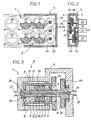
- the vibrator comprises two trains 1, 2, of eccentric weights rotatably mounted by means of shafts A 1 , A 2 , A n , A ' 1 , A' 2 , A ' n , parallel to a transverse axis XX 'and the ends of which engage in bearings carried by two parallel flanges 3, 4 constituting the two lateral sides of a housing 5.
- Each of the weights M, M ' is associated with a pinion P arranged and dimensioned so that the pinions P associated with the same train 1, 2 weights M, M 'mesh with each other, in successive pairs.
- the rotational drive of the two trains 1, 2 of weights M, M ' is ensured by means of a variable speed motorization comprising two hydraulic motors H 1 , H 2 mounted on the flange 3 at one of the ends of the housing 5.
- the pinion P 1 meshes with the pinion P secured to the flyweight M 'to perform the rotational drive of the train 2.
- the pinion P 6 meshes with the pinion P secured to a flyweight M to perform the rotational drive of the train 1.
- the pinion P 3 could for example mesh with any one of the pinions P associated with the flyweights M of the train 1, while the pinion P 4 could mesh with one any of the pinions P associated with the counterweights M 'of the train 2.
- phase shifter 7 consists of a structure fixed 9, partly cylindrical integral with the flanges 3, 4.
- the tubular shaft 8 includes a cylindrical inner surface successively having a smooth part 11 and a threaded part with helical teeth 12.
- This cylindrical inner surface delimits, with a cylindrical surface of the shouldered shaft 6, an annular space 13 closed, on one side, by a bearing 14 ensuring the rotary and sealed mounting of one of the two shafts 6, 8 relative to the other and, on the other side, by a bottom 15 integral with the shaft 8 through which passes the shaft 6 with sealing.
- the cylindrical surface of the shaft 6 successively comprises a smooth part 16 and a threaded portion 17 with helical teeth.
- the space E 1 between the piston 20, the bottom 15 and the two shafts 6, 8, constitutes a first working chamber (main working chamber) into which a hydraulic fluid can be admitted thanks to an axial channel 25 produced in tree 6.
- This axial channel 25 opens into a rotary joint 26 provided at the end of the shaft 6 and the fixed part of which is integral with the structure 9.
- This fixed part comprises a connection sleeve 27 to which the conduit of a hydraulic phase shift control circuit.
- the space E 2 between the piston 20, the bearing 14 and the two shafts 6, 8, constitutes a second working chamber into which hydraulic fluid can be admitted by virtue of an axial channel 28 produced in the shaft 6.
- This channel opens into a rotating joint 29 provided at the end of the shaft 6 and of which the fixed part which is integral with the structure 9 constitutes a sleeve fitting 30.
- this piston 20 When pressurized fluid is injected into the working chamber E 1 , this piston 20 is subjected to an axial force which tends to move it away from the bottom 15 and therefore to generate a double relative rotation between the two shafts 6, 8 and this, thanks to the combined action of the threads 17, 22 on the threads 12, 24.
- the latter are designed so as to cause a relative double rotation of the shafts 6, 8 which can reach 180 ° (reshaping weights M).
- the PC processor can be equipped with various peripherals usual such as a keyboard / CE screen console, an I printer, etc.
- the accelerometric detector A can be placed on the housing of the vibrator, its sensitive axis being parallel to the axis of propagation of vibrator vibrations.
- the AC conditioner performs a double integration of the sinusoidal signal emitted by the sensor accelerometer A, as well as an analog / digital conversion of this signal.
- the signal transmitted to the processor PC is then a signal representative of the amplitude of the vibrations generated by the vibrator.
- the setpoint that the operator will have to display on the display S will therefore be a value representative of an amplitude of these driving vibrations. This value can be determined after an exploratory phase so that that it corresponds to a sufficient amplitude to ensure sinking but below a harmfulness threshold for neighboring sensitive installations.
- the PC processor controls the distributor D, usually a hydraulic slide, so as to adjust the rotation in one direction or the other of the phase shifter (which rotates at the speed of eccentric weights of the vibrator).
- this solution makes it possible to alleviate the defects of rotary joints.
- these seals do not are not waterproof and are therefore fitted with drains. They only allow therefore not to keep, without regular and frequent corrections, a value of given phase shift.
- the accelerometric detector A can include one or more accelerometric sensors (for example a set of three sensors oriented along three orthogonal axes) placed on the structure which one wishes to protect against vibrations, so as to allow the measurement, in one or more directions, of the amplitude of the vibration at which is subject to this structure.
- accelerometric sensors for example a set of three sensors oriented along three orthogonal axes
- the accelerometric signal delivered by each of the detector accelerometers undergo a transformation in the AC conditioner and dual integration as well as analog / digital conversion.
- the signal present at the output of the AC conditioner which is representative of the particle velocity of the soil is applied to a PC processor input.
- This one may process accelerometric information to deduce a value indicative of the harmfulness of the particulate velocity detected. This value could for example correspond at any time to the signal greatest accelerometer among the signals delivered by all the sensors accelerometric.
- this processor can determine, depending on the parameters received, a harmfulness law as a function of the speed of the motors and / or the amplitude of the vibrations.
- This value indicative of the harmfulness of the particulate speed is compared by the processor PC to a value representative of a harmfulness threshold, determined and entered by the operator.
- the processor can then act, according to the above law, on the hydraulic distributor D in order to increase or reduce the amplitude of the vibrations emitted by the vibrator and / or on the speed variation control CV of the motors H 1 and H 2 to reduce the indicative value of the harmfulness to a value at most equal to the threshold harm value.
- connection between, on the one hand, this detector possibly associated with the conditioner and secondly, the processor may be effected by means of a transmission device distance such as cable or radio link.
- the device according to the invention can comprise several accelerometric detectors respectively installed at several facilities or targets.
- the processor will adjust the amplitude of the vibrator compared to the most restrictive of the targets to be protected.
Landscapes
- Engineering & Computer Science (AREA)
- Life Sciences & Earth Sciences (AREA)
- General Life Sciences & Earth Sciences (AREA)
- Mining & Mineral Resources (AREA)
- Paleontology (AREA)
- Civil Engineering (AREA)
- General Engineering & Computer Science (AREA)
- Structural Engineering (AREA)
- Mechanical Engineering (AREA)
- Apparatuses For Generation Of Mechanical Vibrations (AREA)
- Vibration Prevention Devices (AREA)
- Buildings Adapted To Withstand Abnormal External Influences (AREA)
Abstract
Description
- un arbre menant portant un pignon P3 engrenant avec un pignon P5 solidaire de l'arbre de sortie du moteur H2, et
- un arbre mené portant un pignon P4 engrenant avec un pignon P2 solidaire de l'arbre de sortie du moteur H1.
- un arbre central épaulé (arbre menant 6) qui porte, au niveau de son extrémité adjacente au flasque 4, le pignon P3,
- un arbre tubulaire (arbre mené 8), monté rotatif autour de l'arbre épaulé 6 et qui porte, axialement décalé par rapport au pignon P3, le pignon P4.
- une surface extérieure cylindrique comportant une partie lisse 21 qui coulisse avec étanchéité sur la partie lisse 11 et une partie filetée 22 qui engrène sur la partie taraudée 12 ;
- une surface intérieure cylindrique comprenant une partie lisse 23 qui coulisse avec étanchéité sur la partie lisse de l'arbre 6 et une partie taraudée 24 dont les dentures hélicoïdales sont en prise sur les dentures de la partie filetée 17.
- un distributeur hydraulique D dont les deux sorties D1, D2 sont respectivement reliées, par l'intermédiaire de deux circuits hydrauliques respectifs C1, C2, aux entrées des deux joints tournants 27, 30 du déphaseur 7,
- un détecteur accélérométrique A associé à un conditionneur CA destiné à effectuer un traitement et une numérisation des informations accélérométriques délivrées par le détecteur A,
- un afficheur S apte à effectuer la saisie et l'affichage d'une valeur de consigne,
- un processeur PC pouvant consister en un automate programmable qui détermine l'écart entre les informations délivrées par le conditionneur et la valeur de consigne saisie dans l'afficheur S, et qui commande le distributeur D et donc le déphasage assuré par le déphaseur 7, de manière à annuler ledit écart.
Claims (9)
- Dispositif pour la commande asservie de l'amplitude des vibrations d'un vibrateur à moment variable utilisable à l'enfoncement d'objets dans le sol, ce vibrateur comportant au moins deux trains (1, 2) de masselottes excentriques (M, M') comprenant chacun au moins deux masselottes excentriques (M, M') montées rotatives autour d'arbres solidaires de deux pignons respectifs (P) qui engrènent l'un avec l'autre de manière à tourner en sens inverse l'un par rapport à l'autre sous l'effet d'une motorisation pouvant comprendre un ou plusieurs moteurs (H1, H2), la variation du moment vibratoire engendré par les deux trains (1, 2) de masselottes (M, M') étant obtenue au moyen d'un déphaseur (7) apte à engendrer un déphasage angulaire variable entre les mouvements de rotation des deux trains (1, 2) de masselottes (M, M'),
caractérisé en ce qu'il fait intervenir au moins un détecteur accélérométrique (A) placé de manière à être soumis aux vibrations engendrées par le vibrateur, des moyens pour déduire une valeur représentative de la nocivité des vibrations à partir de données accélérométriques délivrées par le détecteur accélérométrique (A), des moyens (S) pour saisir une valeur de consigne, et des moyens de traitement électronique (P) associés à des moyens d'actionnement (D) agissant sur la commande de déphasage du déphaseur (7) et/ou sur la commande de variation de vitesse de la motorisation de manière à maintenir la valeur représentative de la nocivité des vibrations à un niveau inférieur ou égal à la valeur de consigne. - Dispositif selon la revendication 1,
caractérisé en ce que la valeur de consigne résulte d'essais préalables effectués sur le site. - Dispositif selon l'une des revendications 1 et 2,
caractérisé en ce que les susdits moyens de traitement électroniques sont conçus de manière à déterminer lors d'essais préalables sur le site une loi nocivité/amplitude des vibrations - fréquence des vibrations, cette loi étant ensuite utilisée par le dispositif de commande asservie pour régler l'amplitude et/ou la fréquence des vibrations de manière à maintenir la nocivité des vibrations à un niveau inférieur ou égal à la valeur de consigne. - Dispositif selon l'une des revendications 1 et 2,
caractérisé en ce que le détecteur accélérométrique (A) comprend un accéléromètre placé sur la carcasse vibrante du vibrateur. - Dispositif selon l'une des revendications 1 à 3,
caractérisé en ce que le détecteur accélérométrique (A) est installé au niveau d'une structure à protéger. - Dispositif selon la revendication 5,
caractérisé en ce que la transmission entre le détecteur accélérométrique (A) et les moyens de traitement électroniques (P) est assurée par tout moyen de transmission à distance connu tel que liaison filaire ou liaison radio. - Dispositif selon la revendication 6,
caractérisé en ce que le détecteur accélérométrique (A) comprend trois capteurs accélérométriques axés selon trois axes orthogonaux. - Dispositif selon la revendication 7,
caractérisé en ce qu'à chaque instant, les moyens de traitement électroniques prennent en considération le signal accélérométrique le plus important, parmi les signaux délivrés par les capteurs accélérométriques. - Dispositif selon l'une des revendications 5 à 8,
caractérisé en ce qu'il comprend plusieurs détecteurs accélérométriques (A) respectivement installés au niveau de plusieurs installations ou cibles, les moyens de traitement électroniques réglant alors l'amplitude et/ou la fréquence du vibrateur par rapport à la plus contraignante des cibles à protéger.
Applications Claiming Priority (2)
| Application Number | Priority Date | Filing Date | Title |
|---|---|---|---|
| FR9716753A FR2772805B1 (fr) | 1997-12-24 | 1997-12-24 | Dispositif pour la commande asservie de l'amplitude des vibrations d'un vibrateur a moment variable |
| FR9716753 | 1997-12-24 |
Publications (2)
| Publication Number | Publication Date |
|---|---|
| EP0926300A1 true EP0926300A1 (fr) | 1999-06-30 |
| EP0926300B1 EP0926300B1 (fr) | 2003-07-02 |
Family
ID=9515344
Family Applications (1)
| Application Number | Title | Priority Date | Filing Date |
|---|---|---|---|
| EP98403254A Revoked EP0926300B1 (fr) | 1997-12-24 | 1998-12-21 | Dispositif pour la commande asservie de l'amplitude des vibrations d'un vibrateur à moment variable |
Country Status (6)
| Country | Link |
|---|---|
| US (1) | US6345546B1 (fr) |
| EP (1) | EP0926300B1 (fr) |
| AT (1) | ATE244336T1 (fr) |
| DE (1) | DE69816017T2 (fr) |
| ES (1) | ES2205419T3 (fr) |
| FR (1) | FR2772805B1 (fr) |
Cited By (8)
| Publication number | Priority date | Publication date | Assignee | Title |
|---|---|---|---|---|
| US6769838B2 (en) | 2001-10-31 | 2004-08-03 | Caterpillar Paving Products Inc | Variable vibratory mechanism |
| RU2273529C1 (ru) * | 2005-03-01 | 2006-04-10 | Закрытое Акционерное Общество "Вектор" | Способ вибровозбуждения и устройство для его осуществления |
| EP1967291A1 (fr) * | 2007-03-07 | 2008-09-10 | ABI Anlagentechnik-Baumaschinen-Industriebedarf Maschinenfabrik und Vertriebsgesellschaft mbH | Accélérateur d'oscillations |
| FR2918473A1 (fr) * | 2007-07-03 | 2009-01-09 | Ptc Sa | Systeme d'asservissement d'un groupe hydraulique alimentant en fluide hydraulique un vibrateur. |
| EP2067533A1 (fr) * | 2007-12-06 | 2009-06-10 | ABI Anlagentechnik-Baumaschinen-Industriebedarf Maschinenfabrik und Vertriebsgesellschaft mbH | Vibrateur pour un appareil de fonçage vibratoire |
| EP2085148A1 (fr) * | 2008-01-29 | 2009-08-05 | ABI Anlagentechnik-Baumaschinen-Industriebedarf Maschinenfabrik und Vertriebsgesellschaft mbH | Vibrateur pour un appareil de fonçage vibratoire |
| EP2789402A1 (fr) * | 2013-04-10 | 2014-10-15 | ABI Anlagentechnik-Baumaschinen-Industriebedarf Maschinenfabrik und Vertriebsgesellschaft mbH | Accélérateur d'oscillations |
| US9289799B2 (en) | 2013-04-10 | 2016-03-22 | Abi Anlagentechnik-Baumaschinen-Industriebedarf Maschinenfabrik Und Vertriebsgesellschaft Mbh | Vibration exciter for construction machines |
Families Citing this family (10)
| Publication number | Priority date | Publication date | Assignee | Title |
|---|---|---|---|---|
| FR2850042B1 (fr) * | 2003-01-17 | 2007-05-04 | Hutchinson | Generateur d'efforts dynamiques a balourd |
| US7296949B2 (en) * | 2004-07-07 | 2007-11-20 | Under Pressure Systems, Inc. | Removal of obsolete drill platforms from inland seas and ocean floors |
| EP2024660B1 (fr) * | 2006-06-01 | 2012-04-11 | Lord Corporation | Systeme de controle de vibrations de l'equipement rotatif d'engins volants a ailes rotatives |
| DE202007003532U1 (de) * | 2007-03-07 | 2007-07-05 | Abi Gmbh | Schwingungserreger |
| EP2085149B2 (fr) * | 2008-01-29 | 2021-12-22 | ABI Anlagentechnik-Baumaschinen-Industriebedarf Maschinenfabrik und Vertriebsgesellschaft mbH | Vibrateur pour un appareil de fonçage vibratoire |
| FR2934509B1 (fr) * | 2008-07-30 | 2010-09-10 | Ptc | Vibrateur a moment variable utilisant un dephaseur a jeux reduits |
| EP2158976B1 (fr) * | 2008-08-27 | 2013-08-14 | ABI Anlagentechnik-Baumaschinen-Industriebedarf Maschinenfabrik und Vertriebsgesellschaft mbH | Dispositif de production de vibrations |
| US20110110725A1 (en) * | 2009-11-06 | 2011-05-12 | International Construction Equipment, Inc. | Vibratory pile driving apparatus |
| CN102406379B (zh) * | 2011-10-31 | 2013-10-30 | 中山呼拉拉儿童用品有限公司 | 一种电动摇架的驱动装置 |
| DE102015008015A1 (de) | 2015-06-22 | 2016-12-22 | Liebherr-Werk Nenzing Gmbh | Verfahren zum Steuern einer Vibrationsramme |
Citations (3)
| Publication number | Priority date | Publication date | Assignee | Title |
|---|---|---|---|---|
| US4546425A (en) * | 1982-04-01 | 1985-10-08 | Dynapac Maskin Ab | Procedure and device for optimation of the vibration amplitude in vibratory rollers |
| US5253542A (en) * | 1991-07-15 | 1993-10-19 | Procedes Techniques De Construction | Variable moment vibrator usable for driving objects into the ground |
| US5695298A (en) * | 1993-03-08 | 1997-12-09 | Geodynamik H. Thurner Ab | Control of a compacting machine |
Family Cites Families (4)
| Publication number | Priority date | Publication date | Assignee | Title |
|---|---|---|---|---|
| US5177386A (en) * | 1990-08-30 | 1993-01-05 | Kencho Kobe Co., Ltd. | Vibration generator adjustable during operation |
| FR2692523B1 (fr) * | 1992-06-19 | 1994-10-07 | Procedes Tech Construction | Dispositif pour la commande d'un vibrateur à moment variable. |
| US5725329A (en) * | 1996-05-08 | 1998-03-10 | Chelminski; Stephen | Method, system and apparatus for driving and pulling pilings |
| US5825663A (en) * | 1996-11-04 | 1998-10-20 | Gec-Marconi Aerospace Inc. | Vibration control system |
-
1997
- 1997-12-24 FR FR9716753A patent/FR2772805B1/fr not_active Expired - Lifetime
-
1998
- 1998-12-21 ES ES98403254T patent/ES2205419T3/es not_active Expired - Lifetime
- 1998-12-21 EP EP98403254A patent/EP0926300B1/fr not_active Revoked
- 1998-12-21 AT AT98403254T patent/ATE244336T1/de active
- 1998-12-21 DE DE69816017T patent/DE69816017T2/de not_active Expired - Lifetime
- 1998-12-23 US US09/219,463 patent/US6345546B1/en not_active Expired - Lifetime
Patent Citations (3)
| Publication number | Priority date | Publication date | Assignee | Title |
|---|---|---|---|---|
| US4546425A (en) * | 1982-04-01 | 1985-10-08 | Dynapac Maskin Ab | Procedure and device for optimation of the vibration amplitude in vibratory rollers |
| US5253542A (en) * | 1991-07-15 | 1993-10-19 | Procedes Techniques De Construction | Variable moment vibrator usable for driving objects into the ground |
| US5695298A (en) * | 1993-03-08 | 1997-12-09 | Geodynamik H. Thurner Ab | Control of a compacting machine |
Cited By (10)
| Publication number | Priority date | Publication date | Assignee | Title |
|---|---|---|---|---|
| US6769838B2 (en) | 2001-10-31 | 2004-08-03 | Caterpillar Paving Products Inc | Variable vibratory mechanism |
| RU2273529C1 (ru) * | 2005-03-01 | 2006-04-10 | Закрытое Акционерное Общество "Вектор" | Способ вибровозбуждения и устройство для его осуществления |
| EP1967291A1 (fr) * | 2007-03-07 | 2008-09-10 | ABI Anlagentechnik-Baumaschinen-Industriebedarf Maschinenfabrik und Vertriebsgesellschaft mbH | Accélérateur d'oscillations |
| FR2918473A1 (fr) * | 2007-07-03 | 2009-01-09 | Ptc Sa | Systeme d'asservissement d'un groupe hydraulique alimentant en fluide hydraulique un vibrateur. |
| EP2014835A1 (fr) | 2007-07-03 | 2009-01-14 | Ptc | Système d'asservissement d'un groupe hydraulique alimentant en fluide hydraulique un vibrateur |
| EP2067533A1 (fr) * | 2007-12-06 | 2009-06-10 | ABI Anlagentechnik-Baumaschinen-Industriebedarf Maschinenfabrik und Vertriebsgesellschaft mbH | Vibrateur pour un appareil de fonçage vibratoire |
| EP2085148A1 (fr) * | 2008-01-29 | 2009-08-05 | ABI Anlagentechnik-Baumaschinen-Industriebedarf Maschinenfabrik und Vertriebsgesellschaft mbH | Vibrateur pour un appareil de fonçage vibratoire |
| EP2789402A1 (fr) * | 2013-04-10 | 2014-10-15 | ABI Anlagentechnik-Baumaschinen-Industriebedarf Maschinenfabrik und Vertriebsgesellschaft mbH | Accélérateur d'oscillations |
| US9289799B2 (en) | 2013-04-10 | 2016-03-22 | Abi Anlagentechnik-Baumaschinen-Industriebedarf Maschinenfabrik Und Vertriebsgesellschaft Mbh | Vibration exciter for construction machines |
| EP2789402B1 (fr) | 2013-04-10 | 2017-05-17 | ABI Anlagentechnik-Baumaschinen-Industriebedarf Maschinenfabrik und Vertriebsgesellschaft mbH | Accélérateur d'oscillations |
Also Published As
| Publication number | Publication date |
|---|---|
| FR2772805B1 (fr) | 2000-02-25 |
| EP0926300B1 (fr) | 2003-07-02 |
| DE69816017T2 (de) | 2004-05-27 |
| US6345546B1 (en) | 2002-02-12 |
| FR2772805A1 (fr) | 1999-06-25 |
| DE69816017D1 (de) | 2003-08-07 |
| ES2205419T3 (es) | 2004-05-01 |
| ATE244336T1 (de) | 2003-07-15 |
Similar Documents
| Publication | Publication Date | Title |
|---|---|---|
| EP0926300B1 (fr) | Dispositif pour la commande asservie de l'amplitude des vibrations d'un vibrateur à moment variable | |
| EP2018308B1 (fr) | Systeme de direction assistee electrique de vehicule automobile | |
| EP0505976B1 (fr) | Dispositif pour compenser une force vibratoire ou un couple vibratoire subi par une corps | |
| US8061441B2 (en) | Autonomous excavating apparatus | |
| CN106124126B (zh) | 整车状态下传动系动不平衡分离的测试分析方法 | |
| EP0066494B1 (fr) | Système d'analyse par visualisation des mouvements vibratoires d'une machine tournante | |
| FR2657834A1 (fr) | Dispositif de commande de la direction d'un vehicule. | |
| FR2757440A1 (fr) | Plateforme hexapode et dispositifs d'articulation spherique utilisables pour sa realisation | |
| EP1046781A1 (fr) | Méthode et système de détection du déplacement longitudinal d'un outil de forage | |
| EP3129273B1 (fr) | Estimation du vieillissement d'une direction assistée | |
| JP6737363B1 (ja) | 動力計制御装置 | |
| FR2794834A1 (fr) | Procede de mise en oeuvre d'une transmission et transmission convenant a l'application de ce procede | |
| FR2580582A1 (fr) | Procede et dispositif d'amortissement de nutation de satellite par commande d'orientation de masses presentant un produit d'inertie variable | |
| FR2550390A1 (fr) | Monture d'antenne a stabilisation passive | |
| US11514728B2 (en) | Drive system for rotating a wheel of a landing gear having a transmission error measurement apparatus | |
| JP5981120B2 (ja) | 風力発電装置の状態監視システム | |
| EP1127275B1 (fr) | Procede et appareil pour mesurer la portance d'une plateforme | |
| EP0426079A1 (fr) | Procédé de détermination de paramètres d'appui d'un véhicule et véhicule d'intervention pour sols accidentés | |
| EP1541394B1 (fr) | Système de débrayage d'une barre antiroulis de véhicule automobile | |
| FR2466567A1 (fr) | Dispositif de bourrage pour bourreuse de voies ferrees | |
| RU2104172C1 (ru) | Способ стабилизации крутящего момента на ведущих колесах транспортного средства и устройство, его осуществляющее | |
| FR2514500A1 (fr) | Procede et appareil de mesure de couple sans contact | |
| Zhang et al. | Gearboxes: indirect identification of dynamic forces transmitted to housing through bearings | |
| FR2681310A1 (fr) | Dispositif pour la detection du givrage des pales d'un rotor d'aeronef. | |
| WO2006095070A1 (fr) | Installation et procede de sollicitation mecanique d'echantillon au moyen d'un packer |
Legal Events
| Date | Code | Title | Description |
|---|---|---|---|
| PUAI | Public reference made under article 153(3) epc to a published international application that has entered the european phase |
Free format text: ORIGINAL CODE: 0009012 |
|
| 17P | Request for examination filed |
Effective date: 19981229 |
|
| AK | Designated contracting states |
Kind code of ref document: A1 Designated state(s): AT BE CH DE ES GB IT LI LU NL |
|
| AX | Request for extension of the european patent |
Free format text: AL;LT;LV;MK;RO;SI |
|
| AKX | Designation fees paid |
Free format text: AT BE CH DE ES GB IT LI LU NL |
|
| GRAH | Despatch of communication of intention to grant a patent |
Free format text: ORIGINAL CODE: EPIDOS IGRA |
|
| GRAH | Despatch of communication of intention to grant a patent |
Free format text: ORIGINAL CODE: EPIDOS IGRA |
|
| GRAA | (expected) grant |
Free format text: ORIGINAL CODE: 0009210 |
|
| AK | Designated contracting states |
Designated state(s): AT BE CH DE ES GB IT LI LU NL |
|
| REG | Reference to a national code |
Ref country code: GB Ref legal event code: FG4D Free format text: NOT ENGLISH |
|
| REG | Reference to a national code |
Ref country code: CH Ref legal event code: EP |
|
| REF | Corresponds to: |
Ref document number: 69816017 Country of ref document: DE Date of ref document: 20030807 Kind code of ref document: P |
|
| REG | Reference to a national code |
Ref country code: CH Ref legal event code: NV Representative=s name: BUGNION S.A. |
|
| GBT | Gb: translation of ep patent filed (gb section 77(6)(a)/1977) |
Effective date: 20031010 |
|
| PLBQ | Unpublished change to opponent data |
Free format text: ORIGINAL CODE: EPIDOS OPPO |
|
| PLBI | Opposition filed |
Free format text: ORIGINAL CODE: 0009260 |
|
| 26 | Opposition filed |
Opponent name: THYSSENKRUPP GFT TIEFBAUTECHNIK GBMH Effective date: 20040302 |
|
| REG | Reference to a national code |
Ref country code: ES Ref legal event code: FG2A Ref document number: 2205419 Country of ref document: ES Kind code of ref document: T3 |
|
| PLAX | Notice of opposition and request to file observation + time limit sent |
Free format text: ORIGINAL CODE: EPIDOSNOBS2 |
|
| PLBQ | Unpublished change to opponent data |
Free format text: ORIGINAL CODE: EPIDOS OPPO |
|
| PLAB | Opposition data, opponent's data or that of the opponent's representative modified |
Free format text: ORIGINAL CODE: 0009299OPPO |
|
| R26 | Opposition filed (corrected) |
Opponent name: THYSSENKRUPP GFT TIEFBAUTECHNIK GBMH Effective date: 20040302 |
|
| NLR1 | Nl: opposition has been filed with the epo |
Opponent name: THYSSENKRUPP GFT TIEFBAUTECHNIK GBMH |
|
| NLR1 | Nl: opposition has been filed with the epo |
Opponent name: THYSSENKRUPP GFT TIEFBAUTECHNIK GBMH |
|
| PLAX | Notice of opposition and request to file observation + time limit sent |
Free format text: ORIGINAL CODE: EPIDOSNOBS2 |
|
| PLBB | Reply of patent proprietor to notice(s) of opposition received |
Free format text: ORIGINAL CODE: EPIDOSNOBS3 |
|
| PLAY | Examination report in opposition despatched + time limit |
Free format text: ORIGINAL CODE: EPIDOSNORE2 |
|
| PLAH | Information related to despatch of examination report in opposition + time limit modified |
Free format text: ORIGINAL CODE: EPIDOSCORE2 |
|
| PLBC | Reply to examination report in opposition received |
Free format text: ORIGINAL CODE: EPIDOSNORE3 |
|
| PGFP | Annual fee paid to national office [announced via postgrant information from national office to epo] |
Ref country code: LU Payment date: 20081219 Year of fee payment: 11 |
|
| REG | Reference to a national code |
Ref country code: CH Ref legal event code: NV Representative=s name: CABINET MOUTARD |
|
| RDAF | Communication despatched that patent is revoked |
Free format text: ORIGINAL CODE: EPIDOSNREV1 |
|
| APAH | Appeal reference modified |
Free format text: ORIGINAL CODE: EPIDOSCREFNO |
|
| APBM | Appeal reference recorded |
Free format text: ORIGINAL CODE: EPIDOSNREFNO |
|
| APBP | Date of receipt of notice of appeal recorded |
Free format text: ORIGINAL CODE: EPIDOSNNOA2O |
|
| APBQ | Date of receipt of statement of grounds of appeal recorded |
Free format text: ORIGINAL CODE: EPIDOSNNOA3O |
|
| PGFP | Annual fee paid to national office [announced via postgrant information from national office to epo] |
Ref country code: AT Payment date: 20101119 Year of fee payment: 13 |
|
| PGFP | Annual fee paid to national office [announced via postgrant information from national office to epo] |
Ref country code: IT Payment date: 20101125 Year of fee payment: 13 Ref country code: GB Payment date: 20101213 Year of fee payment: 13 |
|
| PG25 | Lapsed in a contracting state [announced via postgrant information from national office to epo] |
Ref country code: LU Free format text: LAPSE BECAUSE OF NON-PAYMENT OF DUE FEES Effective date: 20091221 |
|
| REG | Reference to a national code |
Ref country code: CH Ref legal event code: PFA Owner name: PTC Free format text: PTC#158 RUE DIDEROT#93500 PANTIN (FR) -TRANSFER TO- PTC#158 RUE DIDEROT#93500 PANTIN (FR) |
|
| PGFP | Annual fee paid to national office [announced via postgrant information from national office to epo] |
Ref country code: CH Payment date: 20111227 Year of fee payment: 14 Ref country code: ES Payment date: 20111222 Year of fee payment: 14 |
|
| REG | Reference to a national code |
Ref country code: DE Ref legal event code: R103 Ref document number: 69816017 Country of ref document: DE Ref country code: DE Ref legal event code: R064 Ref document number: 69816017 Country of ref document: DE |
|
| APBU | Appeal procedure closed |
Free format text: ORIGINAL CODE: EPIDOSNNOA9O |
|
| PGFP | Annual fee paid to national office [announced via postgrant information from national office to epo] |
Ref country code: BE Payment date: 20111219 Year of fee payment: 14 |
|
| RDAG | Patent revoked |
Free format text: ORIGINAL CODE: 0009271 |
|
| STAA | Information on the status of an ep patent application or granted ep patent |
Free format text: STATUS: PATENT REVOKED |
|
| REG | Reference to a national code |
Ref country code: CH Ref legal event code: PL |
|
| 27W | Patent revoked |
Effective date: 20120323 |
|
| GBPR | Gb: patent revoked under art. 102 of the ep convention designating the uk as contracting state |
Effective date: 20120323 |
|
| PGFP | Annual fee paid to national office [announced via postgrant information from national office to epo] |
Ref country code: DE Payment date: 20120222 Year of fee payment: 14 |
|
| REG | Reference to a national code |
Ref country code: DE Ref legal event code: R107 Ref document number: 69816017 Country of ref document: DE Effective date: 20120712 |
|
| PG25 | Lapsed in a contracting state [announced via postgrant information from national office to epo] |
Ref country code: CH Free format text: LAPSE BECAUSE OF THE APPLICANT RENOUNCES Effective date: 20030707 Ref country code: LI Free format text: LAPSE BECAUSE OF THE APPLICANT RENOUNCES Effective date: 20030707 |
|
| PGFP | Annual fee paid to national office [announced via postgrant information from national office to epo] |
Ref country code: NL Payment date: 20120102 Year of fee payment: 14 |
|
| REG | Reference to a national code |
Ref country code: AT Ref legal event code: MM01 Ref document number: 244336 Country of ref document: AT Kind code of ref document: T Effective date: 20121221 |