EP2085149B2 - Vibrateur pour un appareil de fonçage vibratoire - Google Patents
Vibrateur pour un appareil de fonçage vibratoire Download PDFInfo
- Publication number
- EP2085149B2 EP2085149B2 EP08001601.7A EP08001601A EP2085149B2 EP 2085149 B2 EP2085149 B2 EP 2085149B2 EP 08001601 A EP08001601 A EP 08001601A EP 2085149 B2 EP2085149 B2 EP 2085149B2
- Authority
- EP
- European Patent Office
- Prior art keywords
- vibrator
- accordance
- sensor
- measuring
- pile driver
- Prior art date
- Legal status (The legal status is an assumption and is not a legal conclusion. Google has not performed a legal analysis and makes no representation as to the accuracy of the status listed.)
- Active
Links
Images

Classifications
-
- B—PERFORMING OPERATIONS; TRANSPORTING
- B06—GENERATING OR TRANSMITTING MECHANICAL VIBRATIONS IN GENERAL
- B06B—METHODS OR APPARATUS FOR GENERATING OR TRANSMITTING MECHANICAL VIBRATIONS OF INFRASONIC, SONIC, OR ULTRASONIC FREQUENCY, e.g. FOR PERFORMING MECHANICAL WORK IN GENERAL
- B06B1/00—Methods or apparatus for generating mechanical vibrations of infrasonic, sonic, or ultrasonic frequency
- B06B1/10—Methods or apparatus for generating mechanical vibrations of infrasonic, sonic, or ultrasonic frequency making use of mechanical energy
- B06B1/16—Methods or apparatus for generating mechanical vibrations of infrasonic, sonic, or ultrasonic frequency making use of mechanical energy operating with systems involving rotary unbalanced masses
- B06B1/161—Adjustable systems, i.e. where amplitude or direction of frequency of vibration can be varied
- B06B1/166—Where the phase-angle of masses mounted on counter-rotating shafts can be varied, e.g. variation of the vibration phase
-
- E—FIXED CONSTRUCTIONS
- E02—HYDRAULIC ENGINEERING; FOUNDATIONS; SOIL SHIFTING
- E02D—FOUNDATIONS; EXCAVATIONS; EMBANKMENTS; UNDERGROUND OR UNDERWATER STRUCTURES
- E02D7/00—Methods or apparatus for placing sheet pile bulkheads, piles, mouldpipes, or other moulds
- E02D7/18—Placing by vibrating
Definitions
- the invention relates to a vibration generator for a vibration pile driver according to the preamble of claim 1.
- the invention also relates to a vibration pile driver according to claim 7.
- vibration generators are used to introduce objects, such as profiles, into the ground or to pull them out of the ground, or to compact soil material.
- the soil is stimulated by vibration and thus reaches a "pseudo-liquid" state.
- the pile can then be pushed into the subsoil by static load.
- the vibration is characterized by a linear movement and is generated by unbalances rotating in opposite directions in pairs within a vibrator gear.
- Vibration generators are characterized by the rotating imbalance and the maximum speed.
- Such vibration generators are, for example, in EP 0 951 949 A1 or DE 195 43 910 A1 disclosed.
- the vibration generators are linear vibration exciters whose centrifugal force is generated by rotating imbalances. These vibration exciters move at a variable speed.
- the size of the imbalance is also referred to as the "static moment".
- the course of the speed of the linear vibration exciter corresponds to a periodically recurring function, for example a sine function, but it can also take other forms.
- Vibration generators are operated with hydraulic drives, which set the shafts on which the unbalances are arranged in rotation.
- Such hydraulic drives have a performance curve which is dependent on the operating speed or the operating pressure.
- a higher static torque can be achieved through a lower speed, which at the same time causes a higher floor vibration.
- Floor vibrations are to be avoided in the inner city area.
- These can be reduced by operating at a higher speed, which at the same time reduces the static torque.
- These measures prove to be problematic, since the required drive power and the torque are speed-dependent. If the optimum operating speed range of the hydraulic drive or motor is left, this results in a drop in performance.
- the required torque on the engine is also reduced as the pile mass increases. Accordingly, the pressure gradient across the engine is reduced and the available drive power can only be partially used.
- the invention aims to provide a remedy here.
- the invention is based on the object of creating a vibration generator which enables operation in different speed ranges without a drop in performance. According to the invention, this object is achieved by the features of the characterizing part of claim 1.
- a vibration exciter is created which enables operation in different speed ranges without a drop in performance.
- the use of a hydraulic drive with variable displacement enables the performance curve to be adapted to the speed range required in each case. This counteracts a drop in performance of the drive.
- the absorption volume is understood to be the amount of hydraulic fluid that the hydraulic drive consumes per revolution.
- the power delivered by a hydraulic drive is directly proportional to the displacement, the speed and the pressure gradient.
- the product of displacement and speed gives the volume flow.
- the pressure gradient is the difference between the pressure of the incoming hydraulic fluid (this is usually the pump pressure) and the pressure of the outflowing hydraulic fluid (this is usually the tank pressure).
- a control and regulating circuit which includes a storage unit for storing soil quality or task-specific default data sets with defined operating parameters, from which a required data set can be selected, sensors for the continuous acquisition of the defined operating parameters, an evaluation unit to compare the operating parameters determined with the operating parameters of the selected default data set, a control device coupled to the evaluation unit to control the vibration generator, and a control device coupled to the control device to control the means for adjusting the relative rotational position of the unbalanced masses to one another.
- the vibration generator can be set simply by selecting an operating data set to be selected depending on the task.
- sensors arranged to detect the frequency, the static load and the relative position of the unbalanced masses to each other.
- the sensors preferably include at least one inductive sensor and / or a rotary encoder.
- Such sensors have proven to be durable and robust.
- a sensor for detecting the acceleration of the rotating shafts is advantageously arranged.
- a sensor for detecting the amplitude of the oscillations of the oscillation generator can be arranged.
- a device for the automatic selection of a default data record on the basis of the acceleration values determined.
- an automatic program can be implemented through which the most efficient default values are automatically selected as a function of the task-specific operating situation, without the operator having to intervene.
- a semi-automatic system can also be implemented in which an operating parameter data set is proposed to the operator, which can be confirmed or changed by the operator.
- the evaluation unit advantageously has a programmable logic controller (PLC). This enables flexible control of the vibration generator.
- PLC programmable logic controller
- an acoustic and / or optical warning device for alarming incorrect inputs is provided, which is connected to the evaluation unit. In this way, the operator can be informed of a necessary adjustment or change in the current operating parameters.
- the invention is also based on the object of creating a vibration pile driver which enables operation in different speed ranges without a drop in performance. According to the invention, this object is achieved by the features of claim 7.
- a vibration pile driver is created which enables operation in different speed ranges without a drop in performance.
- a sensor is arranged to detect the forces acting on the pile. By determining this quantity, a characterization of the soil structure is made possible. This characterization can be improved by the preferred arrangement of at least one sensor which can be applied to the penetrating medium and which is connected to the evaluation unit to detect the vibrations of the penetrating medium.
- a sensor for detecting the penetration speed of the pile is preferably provided.
- a device for the automatic selection of a default data set based on the determined forces acting on the pile and / or the determined pile speed and acceleration and / or the recorded vibrations of the penetrating medium.
- an automatic program can be implemented through which the most efficient default values are automatically selected as a function of the task-specific operating situation, without the operator having to intervene.
- a semi-automatic system can also be implemented, in which an operating characteristic data record is proposed to the operator, which can be confirmed or changed by the operator.
- the vibration pile driving device selected as an exemplary embodiment consists essentially of a carrier device 1 on which a vibration generator (vibrator) 3 is arranged so as to be vertically displaceable via a leader 2.
- the vibration generator 3 comprises a housing 31 which is surrounded by a hood 30. Clamping tongs 37 for receiving piling material 4 are arranged on the hood 30.
- the hood 30 is used to guide the vibration generator 3 and transmits the static force of the leader 2 to the vibration generator 3.
- the vibration generator 3 generates a vibration via rotating imbalances 3311, 3321, 3331, 3511, 3521, 3531, which via the clamping pliers 33 on the Ramming 4 is transferred.
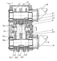
- the vibration generator 3 is designed as a vibrator gear ( Figure 2 ). It essentially consists of a housing 31 in which shafts 33, 35 provided with gear wheels 331, 332, 333, 351, 352, 353 are rotatably mounted.
- the gears 331, 332, 333, 351, 352, 353 are each provided with unbalanced masses 3311, 3321, 3331, 3511, 3521, 3531, the gears of both shafts 33, 35 being connected to one another via gears 3613, 3614 of the rotor shaft 361 of a swivel motor 36 are engaged.
- the gears 331, 332, 333, 351, 352, 353 provided with unbalanced masses 3311, 3321, 3331, 3511, 3521, 3531 can be adjusted in their rotational position relative to one another via the swivel motor 36, whereby the resulting unbalance or the resulting static moment is adjustable.
- Such vibrator gears with rotatably mounted unbalanced masses which can be adjusted in the relative phase position, are known to the person skilled in the art, for example, from DE 20 2007 005 283 U1 known.
- the vibration generator 3 is provided opposite the gears 331, 332, 333, 351, 352, 353 on the inside of the housing 31 with two inductive sensors 310 arranged parallel to the circumference of the gears and spaced apart from one another.
- the inductive Sensors 310 enable the angular acceleration of the rotating unbalanced masses 3311, 3321, 3331, 3511, 3521, 3531 to be recorded.
- the relative position of the unbalanced masses 3311, 3321, 3331, 3511, 3521, 3531 can also be used to determine their relative position to one another.
- an acceleration sensor 311 is arranged on the housing 31 of the vibration generator 3.
- a programmable logic controller (PLC) 7 is arranged as an evaluation unit for processing the signals from sensors 310, 311 and determining the aforementioned variables, which further calculates the static torque present on the basis of the frequency and time offset of the unbalanced masses to one another.
- PLC programmable logic controller
- a sensor system with two inductive sensors that is, one inductive sensor per unbalance pass
- an acceleration sensor attached to the housing of the vibration generator can also be provided.
- the shafts 33, 35 of the vibration generator 3 are connected to hydraulic drives 38 which have a variable absorption volume.
- hydraulic drives 38 which have a variable absorption volume.
- the hydraulic drives 38 are connected to a control module, via which the absorption volume can be adjusted as a function of the respective operating speed range.
- the control module is integrated in the drive 38.
- a memory unit 10 which is connected to the PLC 7 via lines 6, is connected upstream of the PLC 7.
- soil condition-specific default data sets with defined operating parameters are stored. These default values are empirically determined values.
- the PLC 7, together with the storage unit 10, forms an automatic program which selects a corresponding, efficient data set depending on the existing soil properties.
- the data sets are coupled to force and acceleration values to be determined, which are transmitted to the PLC 7 as input variables.
- the vibration emission of the surrounding penetration medium is stored as an influencing variable.
- the force and acceleration values are determined via a force sensor 52 and an acceleration sensor 311.
- the force sensor 52 is set up in such a way that it detects the forces acting on the pile 4, the forces exerted by the leader 2 and the opposing force generated by the penetrating medium results, determined and transmitted to the PLC 7 via lines 6.
- the acceleration sensor 311 is set up in such a way that it determines the penetration speed and acceleration of the pile 4 into the penetration medium 9 and also transmits it to the PLC 7 via lines 6.
- the penetration speed can optionally be determined with an additional sensor (53), preferably a laser for measuring the distance between the vibrator and the floor.
- the force applied can also be determined using an acceleration sensor 311 and the dynamic mass.
- a vibration sensor 54 is applied to the floor 9 at a distance from the penetration point of the pile 4. This vibration sensor 54 determines the vibrations emitted by the ground during the pile-driving process and transmits the recorded vibration values to the PLC 7 via a line 6.
- the default data set assigned to these values (or a value range in which the determined values fall) is selected from a memory unit 10, its default values for comparison with the values provided by the sensors 310 , 311 determined operating parameters can be used.
- the operator of the vibration pile driver it is also possible for the operator of the vibration pile driver to select a data record using a corresponding control panel.
- a controller 8 is arranged in the carrier device 1 and is connected to the memory unit 10 and to the PLC 7 via lines 6.
- the controller 8 is set up in such a way that it calculates the optimal operating parameters of the vibration generator from the static moment determined by the PLC 7 and the acceleration data determined by the sensors 311 against the background of the default parameters of the default data set selected from the storage unit 10.
- the controller 8 is connected to the swivel motor 36 arranged in the vibration generator 3 for changing the relative rotational position of the unbalanced masses to one another.
- the current operating characteristic data recorded by the sensors 310, 311 is matched to the corresponding default values of the selected default data set. If the permissible acceleration values are exceeded, the resulting imbalance or the resulting static moment is readjusted by the swivel motor 36 via the gearwheel 3621.
- an optical and / or acoustic signal can be installed in the operator's stand of the carrier device in order to inform the operator that the permissible acceleration values have been significantly exceeded. As a rule, this indicates the selection of an unsuitable set of operating parameters from the memory unit 10. Activating the signal instructs the operator to check the selection of the default data record and to correct it if necessary.
Landscapes
- Engineering & Computer Science (AREA)
- Life Sciences & Earth Sciences (AREA)
- General Life Sciences & Earth Sciences (AREA)
- Mining & Mineral Resources (AREA)
- Paleontology (AREA)
- Civil Engineering (AREA)
- General Engineering & Computer Science (AREA)
- Structural Engineering (AREA)
- Mechanical Engineering (AREA)
- Placing Or Removing Of Piles Or Sheet Piles, Or Accessories Thereof (AREA)
Claims (10)
- Vibrateur pour un appareil de fonçage vibratoire, comprenant des masselottes rotatives (3321, 3331, 3521, 3531) agencées sur des arbres (33, 35), caractérisé en ce qu'est agencé au moins un entraînement hydraulique (38), à volume d'absorption variable via un module régulateur en fonction de la plage de régime respective, destiné à entraîner les arbres, sachant que des moyens (36) sont agencés pour modifier la position de rotation des masselottes les unes par rapport aux autres, lesquels moyens sont formés par un moteur de pivotement.
- Vibrateur selon la revendication 1, caractérisé en ce qu'est prévu un circuit de commande et de régulation présentant les composantes suivantes:- Une unité mémoire recevant des paquets de données imposés - dans laquelle il est possible de choisir le paquet respectivement nécessaire - spécifiques à la nature du sol et aux tâches à accomplir, paquets qui contiennent des paramètres d'exploitation définis,- Des capteurs (5) permettant de saisir continuellement les paramètres d'exploitation définis,- Une unité d'analyse (7) servant à comparer les paramètres d'exploitation déterminés avec les paramètres d'exploitation provenant des paquets de données imposés qui ont été sélectionnés,- Un dispositif de régulation couplé à l'unité d'analyse (7) pour réguler le moment statique du vibrateur sur la base de valeurs comparatives déterminées par l'unité d'analyse (7),- Un dispositif de commande couplé avec le dispositif de régulation, pour exciter les moyens servant à modifier la position relative de rotation des masselottes les unes par rapport aux autres.
- Vibrateur selon la revendication 1 ou 2, caractérisé en ce que sont agencés des capteurs (5) servant à saisir la fréquence ainsi que la position relative des masselottes les unes par rapport aux autres.
- Vibrateur selon l'une des revendications précédentes, caractérisé en ce qu'au moins un capteur (5) est agencé à l'intérieur du vibrateur (3) pour saisir l'accélération des arbres en train de tourner.
- Vibrateur selon l'une des revendications précédentes, caractérisé en ce qu'au moins un capteur (51) est agencé pour saisir l'accélération du vibrateur.
- Vibrateur selon la revendication 5, caractérisé en ce qu'au moins un capteur (51) est agencé pour saisir l'accélération du vibrateur et en ce qu'est prévu un dispositif servant à sélectionner automatiquement un paquet de données imposé sur la base des valeurs d'accélération déterminées.
- Appareil de fonçage vibratoire comprenant un vibrateur (3) selon l'une des revendications 1 à 6, une jumelle (2) via laquelle le générateur de vibrations (3) est agencé de manière déplaçable, et/ou un réceptacle recevant l'objet à enfoncer (4).
- Appareil de fonçage vibratoire selon la revendication 7, caractérisé en ce qu'est agencé un capteur (52) servant à saisir la force agissant sur l'objet à enfoncer (4).
- Appareil de fonçage vibratoire selon la revendication 7 ou 8, caractérisé en ce qu'est agencé un capteur (53) servant à saisir la vitesse de pénétration.
- Appareil de fonçage vibratoire selon l'une des revendications 7 à 9, caractérisé en ce qu'est prévu au moins un capteur externe (54) - qu'il est possible de fixer sur l'objet pénétrant afin de saisir les vibrations dudit objet - relié à l'unité d'analyse (7).
Priority Applications (3)
| Application Number | Priority Date | Filing Date | Title |
|---|---|---|---|
| DE200820017313 DE202008017313U1 (de) | 2008-01-29 | 2008-01-29 | Schwingungserzeuger für Vibrationsrammgerät |
| EP08001601.7A EP2085149B2 (fr) | 2008-01-29 | 2008-01-29 | Vibrateur pour un appareil de fonçage vibratoire |
| US12/290,104 US8522891B2 (en) | 2008-01-29 | 2008-10-27 | Vibration generator for a vibration pile driver |
Applications Claiming Priority (1)
| Application Number | Priority Date | Filing Date | Title |
|---|---|---|---|
| EP08001601.7A EP2085149B2 (fr) | 2008-01-29 | 2008-01-29 | Vibrateur pour un appareil de fonçage vibratoire |
Publications (3)
| Publication Number | Publication Date |
|---|---|
| EP2085149A1 EP2085149A1 (fr) | 2009-08-05 |
| EP2085149B1 EP2085149B1 (fr) | 2013-07-24 |
| EP2085149B2 true EP2085149B2 (fr) | 2021-12-22 |
Family
ID=39365417
Family Applications (1)
| Application Number | Title | Priority Date | Filing Date |
|---|---|---|---|
| EP08001601.7A Active EP2085149B2 (fr) | 2008-01-29 | 2008-01-29 | Vibrateur pour un appareil de fonçage vibratoire |
Country Status (2)
| Country | Link |
|---|---|
| US (1) | US8522891B2 (fr) |
| EP (1) | EP2085149B2 (fr) |
Families Citing this family (16)
| Publication number | Priority date | Publication date | Assignee | Title |
|---|---|---|---|---|
| EP2085148B1 (fr) * | 2008-01-29 | 2013-09-18 | ABI Anlagentechnik-Baumaschinen-Industriebedarf Maschinenfabrik und Vertriebsgesellschaft mbH | Vibrateur pour un appareil de fonçage vibratoire |
| EP2557233B2 (fr) | 2011-08-12 | 2022-06-01 | ABI Anlagentechnik-Baumaschinen-Industriebedarf Maschinenfabrik und Vertriebsgesellschaft mbH | Appareil de travail doté d'un entraînement hydraulique pour travaux de construction profonds |
| EP2789402B1 (fr) * | 2013-04-10 | 2017-05-17 | ABI Anlagentechnik-Baumaschinen-Industriebedarf Maschinenfabrik und Vertriebsgesellschaft mbH | Accélérateur d'oscillations |
| EP2789403B1 (fr) | 2013-04-10 | 2015-12-16 | ABI Anlagentechnik-Baumaschinen-Industriebedarf Maschinenfabrik und Vertriebsgesellschaft mbH | Générateur de vibrations pour machines de construction |
| DE102013103722B4 (de) | 2013-04-12 | 2016-10-13 | Thyssenkrupp Tiefbautechnik Gmbh | Vibrationsrammanordnung sowie Verfahren zum Betrieb der Vibrationsrammanordnung |
| EP3101179B1 (fr) | 2015-06-03 | 2018-04-18 | ABI Anlagentechnik-Baumaschinen-Industriebedarf Maschinenfabrik und Vertriebsgesellschaft mbH | Appareil de travail, notamment pour un engin de chantier |
| DE102015008015A1 (de) * | 2015-06-22 | 2016-12-22 | Liebherr-Werk Nenzing Gmbh | Verfahren zum Steuern einer Vibrationsramme |
| MY190434A (en) * | 2015-10-12 | 2022-04-21 | Yeow Thium Chin | Apparatus and method for pile set measurement |
| JP6602643B2 (ja) * | 2015-10-29 | 2019-11-06 | 西松建設株式会社 | 振動計測管理システム、及び杭基礎施工方法 |
| EP3243573B1 (fr) | 2016-05-09 | 2018-07-18 | Eurodrill GmbH | Dispositif de production de vibrations |
| DE102017001877A1 (de) * | 2017-02-27 | 2018-08-30 | Liebherr-Werk Nenzing Gmbh | Verfahren zum Erkennen von Hindernissen beim Betrieb einer Vibrationsramme |
| WO2020167243A1 (fr) * | 2019-02-12 | 2020-08-20 | Chin Jia Yi | Appareil de mesure de réglage de pieux |
| DE102023125273A1 (de) * | 2023-09-19 | 2025-03-20 | Liebherr-Werk Nenzing Gmbh | Verfahren zur Überwachung einer Arbeitsmaschine mit Mäkler sowie Arbeitsmaschine mit Mäkler |
| EP4671449A1 (fr) | 2024-06-26 | 2025-12-31 | ABI Anlagentechnik-Baumaschinen-Industriebedarf Maschinenfabrik und Vertriebsgesellschaft mbH | Dispositif et procédé de sécurisation d'un élément de construction souterraine sur une machine de construction souterraine |
| EP4675047A1 (fr) | 2024-07-03 | 2026-01-07 | ABI Anlagentechnik-Baumaschinen-Industriebedarf Maschinenfabrik und Vertriebsgesellschaft mbH | Générateur de vibrations pour sonnettes mécaniques vibrantes |
| EP4675079A1 (fr) | 2024-07-03 | 2026-01-07 | ABI Anlagentechnik-Baumaschinen-Industriebedarf Maschinenfabrik und Vertriebsgesellschaft mbH | Appareil de construction en profondeur spécial et procédé de fonctionnement d'un appareil de construction en profondeur spéciale |
Citations (4)
| Publication number | Priority date | Publication date | Assignee | Title |
|---|---|---|---|---|
| US5355964A (en) † | 1993-07-12 | 1994-10-18 | White John L | Pile driving and/or pile pulling vibratory assembly with counterweights |
| US5903077A (en) † | 1995-09-21 | 1999-05-11 | Moog Inc. | Modular vibratory force generator, and method of operating same |
| US6345564B1 (en) † | 1999-03-30 | 2002-02-12 | The Boeing Company | Semi-levered landing gear and auxiliary strut thereof |
| DE202007005283U1 (de) † | 2007-03-07 | 2007-07-12 | Abi Gmbh | Schwingungserreger |
Family Cites Families (21)
| Publication number | Priority date | Publication date | Assignee | Title |
|---|---|---|---|---|
| DE2442367A1 (de) * | 1974-09-04 | 1976-03-18 | Tracto Technik | Hydraulisch angetriebener vibrator |
| US4211121A (en) * | 1976-09-01 | 1980-07-08 | Fmc Corporation | Vibrator with eccentric weights |
| US4113034A (en) * | 1977-06-20 | 1978-09-12 | Raygo, Inc. | Uniaxial variable vibratory force generator |
| DE2732934C2 (de) * | 1977-07-21 | 1985-09-12 | Bomag-Menck GmbH, 5407 Boppard | Verfahren und Vorrichtung zum Rammen und Ziehen |
| DE3043719A1 (de) * | 1980-11-20 | 1982-06-24 | Wacker-Werke Gmbh & Co Kg, 8077 Reichertshofen | Schwingungserreger fuer bodenverdichtungsgeraete |
| US4766771A (en) * | 1984-11-15 | 1988-08-30 | Outboard Marine Corporation | Shaking apparatus |
| US4793196A (en) * | 1987-03-24 | 1988-12-27 | Key Technology, Inc. | Gear coupled, counter-rotating vibratory drive assembly |
| US4819740A (en) * | 1987-11-16 | 1989-04-11 | Vulcan Iron Works Inc. | Vibratory hammer/extractor |
| US5177386A (en) * | 1990-08-30 | 1993-01-05 | Kencho Kobe Co., Ltd. | Vibration generator adjustable during operation |
| FR2692523B1 (fr) * | 1992-06-19 | 1994-10-07 | Procedes Tech Construction | Dispositif pour la commande d'un vibrateur à moment variable. |
| DE4301368A1 (de) * | 1992-07-03 | 1994-01-05 | Gedib Ingbuero Innovation | Vorrichtung und Verfahren zur Schwingungserregung |
| US5375664A (en) * | 1993-06-15 | 1994-12-27 | Mcdowell; Michael M. | Pile driver |
| DE4425905A1 (de) * | 1994-07-21 | 1996-01-25 | Bald Hubert | Vorrichtung und Verfahren zur Kompensation von Querschwingungen an Unwuchtvibratoren mit vorgegebener Schwingrichtung |
| DE19543910A1 (de) | 1995-11-26 | 1997-05-28 | Gedib Ingbuero Innovation | Verstelleinrichtung für einen Unwucht-Richtschwinger mit verstellbarem Fliehmoment |
| FR2772805B1 (fr) * | 1997-12-24 | 2000-02-25 | Procedes Tech Const | Dispositif pour la commande asservie de l'amplitude des vibrations d'un vibrateur a moment variable |
| NL1008635C2 (nl) * | 1998-03-19 | 1999-09-21 | Ice B V | Trilinrichting en werkwijze voor het trillend aandrijven van een voorwerp. |
| NL1008965C2 (nl) * | 1998-04-22 | 1999-10-25 | Int Construction Equipment B V | Werkwijze en inrichting voor het trillend aandrijven van een voorwerp. |
| US6769838B2 (en) * | 2001-10-31 | 2004-08-03 | Caterpillar Paving Products Inc | Variable vibratory mechanism |
| US7404449B2 (en) * | 2003-05-12 | 2008-07-29 | Bermingham Construction Limited | Pile driving control apparatus and pile driving system |
| DE102005022627A1 (de) | 2005-05-11 | 2006-11-16 | Ammann Verdichtung Gmbh | Bodenverdichtungsgerät |
| EP2085148B1 (fr) * | 2008-01-29 | 2013-09-18 | ABI Anlagentechnik-Baumaschinen-Industriebedarf Maschinenfabrik und Vertriebsgesellschaft mbH | Vibrateur pour un appareil de fonçage vibratoire |
-
2008
- 2008-01-29 EP EP08001601.7A patent/EP2085149B2/fr active Active
- 2008-10-27 US US12/290,104 patent/US8522891B2/en active Active
Patent Citations (4)
| Publication number | Priority date | Publication date | Assignee | Title |
|---|---|---|---|---|
| US5355964A (en) † | 1993-07-12 | 1994-10-18 | White John L | Pile driving and/or pile pulling vibratory assembly with counterweights |
| US5903077A (en) † | 1995-09-21 | 1999-05-11 | Moog Inc. | Modular vibratory force generator, and method of operating same |
| US6345564B1 (en) † | 1999-03-30 | 2002-02-12 | The Boeing Company | Semi-levered landing gear and auxiliary strut thereof |
| DE202007005283U1 (de) † | 2007-03-07 | 2007-07-12 | Abi Gmbh | Schwingungserreger |
Non-Patent Citations (7)
| Title |
|---|
| Auszug aus Wikipedia zum Schluckvolumen † |
| Broschüre „Universaler Anbauverdichter Rütteltiger XP", Fa. Riedlberger † |
| Fachartikel „Flüssige Leistungsübertragung - Hydraulik an Baumaschinen - Teil 1" † |
| Fachartikel „Flüssige Leistungsübertragung - Hydraulik an Baumaschinen - Teil 2" † |
| Foto des Standes der Fa. Riedlberger auf der BAUMA 2007 † |
| Preisliste 2007 Rütteltiger XP, Fa. Riedlberger † |
| Prospekt BAUER AR 90/AR 180. BAUER Spezialtiefbau GmbH, Marz 1995 † |
Also Published As
| Publication number | Publication date |
|---|---|
| US20090189467A1 (en) | 2009-07-30 |
| EP2085149B1 (fr) | 2013-07-24 |
| EP2085149A1 (fr) | 2009-08-05 |
| US8522891B2 (en) | 2013-09-03 |
Similar Documents
| Publication | Publication Date | Title |
|---|---|---|
| EP2085149B2 (fr) | Vibrateur pour un appareil de fonçage vibratoire | |
| EP2085148B1 (fr) | Vibrateur pour un appareil de fonçage vibratoire | |
| EP2928611B1 (fr) | Procédé de réglage d'entraînement et système d'entraînement fonctionnant selon ce procédé | |
| DE102015006398B3 (de) | Bodenverdichtung mit einem Baggeranbauverdichter | |
| EP3252232B2 (fr) | Compacteur et son procédé de fonctionnement | |
| EP2627826B1 (fr) | Méthode pour la détermination de la rigidité et/ou de l'amortissement d'un domaine d'une solidité | |
| EP2984241B1 (fr) | Ensemble de battage par vibrations et procédé de fonctionnement d'un ensemble de battage par vibrations | |
| DE102010060843B4 (de) | Verfahren und Vorrichtung zum Messen von Bodenparametern mittels Verdichtungsmaschinen | |
| EP2557233B2 (fr) | Appareil de travail doté d'un entraînement hydraulique pour travaux de construction profonds | |
| EP2558649B1 (fr) | Agencement pour fournir une force de pression pulsée | |
| DE102007018353A1 (de) | Schwingungserreger für Bodenverdichtungsvorrichtungen | |
| EP1285135A1 (fr) | Dispositif de compactage du sol avec detection des oscillations | |
| DE102005036842A1 (de) | Steuersystem und Steuerverfahren für einen Schwingungsmechanismus | |
| EP2067533B2 (fr) | Vibrateur pour un appareil de fonçage vibratoire | |
| EP3587668A1 (fr) | Engin de construction automoteur et procédé de traitement des revêtements de sol | |
| EP3383543B1 (fr) | Procédé pour régler un espace de concassage | |
| EP1722036A2 (fr) | Engin de compactage du sol | |
| EP3589459B1 (fr) | Robot à bras articulé et procédé d'usinage par enlèvement de copeaux d'une pièce au moyen du robot à bras articulé | |
| DE10220057B4 (de) | Vorrichtung zur Kompensation von durch Massenkräfte verursachten Schwingungen | |
| DE102018001505A1 (de) | Verfahren zum spanenden Bearbeiten eines Werkstückes mittels einem Knickarmroboter | |
| DE202007019293U1 (de) | Schwingungserreger für Bodenverdichtungsvorrichtungen | |
| DE202008017313U1 (de) | Schwingungserzeuger für Vibrationsrammgerät | |
| EP3819434B1 (fr) | Procédé et dispositif de fraisage de paroi de fente permettant de créer une fente fraisée dans le sol | |
| DE102011100881B4 (de) | Schwingungserzeuger | |
| DE10220056A1 (de) | Kompensationsvorrichtung sowie Verfahren zum Anfahren einer derartigen Vorrichtung |
Legal Events
| Date | Code | Title | Description |
|---|---|---|---|
| PUAI | Public reference made under article 153(3) epc to a published international application that has entered the european phase |
Free format text: ORIGINAL CODE: 0009012 |
|
| 17P | Request for examination filed |
Effective date: 20080913 |
|
| AK | Designated contracting states |
Kind code of ref document: A1 Designated state(s): AT BE BG CH CY CZ DE DK EE ES FI FR GB GR HR HU IE IS IT LI LT LU LV MC MT NL NO PL PT RO SE SI SK TR |
|
| AX | Request for extension of the european patent |
Extension state: AL BA MK RS |
|
| AKX | Designation fees paid |
Designated state(s): DE FR GB NL |
|
| 17Q | First examination report despatched |
Effective date: 20101026 |
|
| GRAP | Despatch of communication of intention to grant a patent |
Free format text: ORIGINAL CODE: EPIDOSNIGR1 |
|
| GRAS | Grant fee paid |
Free format text: ORIGINAL CODE: EPIDOSNIGR3 |
|
| INTG | Intention to grant announced |
Effective date: 20130522 |
|
| GRAA | (expected) grant |
Free format text: ORIGINAL CODE: 0009210 |
|
| AK | Designated contracting states |
Kind code of ref document: B1 Designated state(s): DE FR GB NL |
|
| REG | Reference to a national code |
Ref country code: GB Ref legal event code: FG4D Free format text: NOT ENGLISH |
|
| REG | Reference to a national code |
Ref country code: NL Ref legal event code: T3 |
|
| REG | Reference to a national code |
Ref country code: DE Ref legal event code: R096 Ref document number: 502008010347 Country of ref document: DE Effective date: 20130919 |
|
| PLBI | Opposition filed |
Free format text: ORIGINAL CODE: 0009260 |
|
| 26 | Opposition filed |
Opponent name: BAUER MASCHINEN GMBH Effective date: 20140407 |
|
| PLAX | Notice of opposition and request to file observation + time limit sent |
Free format text: ORIGINAL CODE: EPIDOSNOBS2 |
|
| REG | Reference to a national code |
Ref country code: DE Ref legal event code: R026 Ref document number: 502008010347 Country of ref document: DE Effective date: 20140407 |
|
| PLBB | Reply of patent proprietor to notice(s) of opposition received |
Free format text: ORIGINAL CODE: EPIDOSNOBS3 |
|
| REG | Reference to a national code |
Ref country code: FR Ref legal event code: PLFP Year of fee payment: 9 |
|
| RDAF | Communication despatched that patent is revoked |
Free format text: ORIGINAL CODE: EPIDOSNREV1 |
|
| APBM | Appeal reference recorded |
Free format text: ORIGINAL CODE: EPIDOSNREFNO |
|
| APBP | Date of receipt of notice of appeal recorded |
Free format text: ORIGINAL CODE: EPIDOSNNOA2O |
|
| APAH | Appeal reference modified |
Free format text: ORIGINAL CODE: EPIDOSCREFNO |
|
| APBQ | Date of receipt of statement of grounds of appeal recorded |
Free format text: ORIGINAL CODE: EPIDOSNNOA3O |
|
| REG | Reference to a national code |
Ref country code: FR Ref legal event code: PLFP Year of fee payment: 10 |
|
| REG | Reference to a national code |
Ref country code: FR Ref legal event code: PLFP Year of fee payment: 11 |
|
| PLAB | Opposition data, opponent's data or that of the opponent's representative modified |
Free format text: ORIGINAL CODE: 0009299OPPO |
|
| R26 | Opposition filed (corrected) |
Opponent name: BAUER MASCHINEN GMBH Effective date: 20140407 |
|
| APBU | Appeal procedure closed |
Free format text: ORIGINAL CODE: EPIDOSNNOA9O |
|
| PUAH | Patent maintained in amended form |
Free format text: ORIGINAL CODE: 0009272 |
|
| STAA | Information on the status of an ep patent application or granted ep patent |
Free format text: STATUS: PATENT MAINTAINED AS AMENDED |
|
| 27A | Patent maintained in amended form |
Effective date: 20211222 |
|
| AK | Designated contracting states |
Kind code of ref document: B2 Designated state(s): DE FR GB NL |
|
| REG | Reference to a national code |
Ref country code: DE Ref legal event code: R102 Ref document number: 502008010347 Country of ref document: DE |
|
| REG | Reference to a national code |
Ref country code: NL Ref legal event code: FP |
|
| PGFP | Annual fee paid to national office [announced via postgrant information from national office to epo] |
Ref country code: GB Payment date: 20220125 Year of fee payment: 15 |
|
| P01 | Opt-out of the competence of the unified patent court (upc) registered |
Effective date: 20230513 |
|
| GBPC | Gb: european patent ceased through non-payment of renewal fee |
Effective date: 20230129 |
|
| PG25 | Lapsed in a contracting state [announced via postgrant information from national office to epo] |
Ref country code: GB Free format text: LAPSE BECAUSE OF NON-PAYMENT OF DUE FEES Effective date: 20230129 |
|
| PGFP | Annual fee paid to national office [announced via postgrant information from national office to epo] |
Ref country code: NL Payment date: 20260121 Year of fee payment: 19 |
|
| PGFP | Annual fee paid to national office [announced via postgrant information from national office to epo] |
Ref country code: DE Payment date: 20260116 Year of fee payment: 19 |
|
| PGFP | Annual fee paid to national office [announced via postgrant information from national office to epo] |
Ref country code: FR Payment date: 20260128 Year of fee payment: 19 |