EP0926301A2 - Clapet anti-refoulement - Google Patents
Clapet anti-refoulement Download PDFInfo
- Publication number
- EP0926301A2 EP0926301A2 EP98122778A EP98122778A EP0926301A2 EP 0926301 A2 EP0926301 A2 EP 0926301A2 EP 98122778 A EP98122778 A EP 98122778A EP 98122778 A EP98122778 A EP 98122778A EP 0926301 A2 EP0926301 A2 EP 0926301A2
- Authority
- EP
- European Patent Office
- Prior art keywords
- emergency
- operating
- lock
- closure
- operating position
- Prior art date
- Legal status (The legal status is an assumption and is not a legal conclusion. Google has not performed a legal analysis and makes no representation as to the accuracy of the status listed.)
- Granted
Links
Images


Classifications
-
- E—FIXED CONSTRUCTIONS
- E03—WATER SUPPLY; SEWERAGE
- E03F—SEWERS; CESSPOOLS
- E03F7/00—Other installations or implements for operating sewer systems, e.g. for preventing or indicating stoppage; Emptying cesspools
- E03F7/02—Shut-off devices
- E03F7/04—Valves for preventing return flow
Definitions
- the invention relates to a backflow stop device according to the preamble of claim 1.
- a backflow stop device for one Sewage line for sewage containing faeces is out of the EP 0 307 698 A1 is known.
- This well-known Backflow stop device has two from each other independent locks on, an operating lock and an emergency lock.
- the operating lock is with a Rotary drive connected.
- a control device that Receiving signals from a liquid sensor is for Control of the rotary drive is provided. If not Back pressure is present and the liquid sensor is none Emits signals to the control device, the Rotary drive the operating lock in a forced open position in which the wastewater can drain. At The liquid sensor indicates a backflow Signals to the control device, which then the Actuates the rotary drive in such a way that the operating lock from the open position to a closed position, in which the sewage pipe is closed is moved.
- the emergency stopper of the known backflow stop device is in a forced connection with one Manual control lever. In a first position of the The manual override will force the emergency lock kept in an open position. In a second The position of the manual operating lever becomes the emergency lock locked in a closed position.
- the first position of the manual control lever in which the Emergency lock is forcibly opened, corresponds to the normal working position.
- the second position of the Manual operating lever in which the emergency lock in the Locked position is locked regardless of the position of the operating closure no drainage of the Sewage and is only chosen if for example in the event of a long absence, a closure the sewage pipe is to be ensured.
- the invention is based on the technical problem Backflow stop device for a sewer pipe Generic type in such a way that also at back pressure suddenly occurring to protect against Backflow is guaranteed.
- the emergency closure is designed so that it can be brought into a third operating position, in which it allows drainage of the waste water if there is no back pressure, and if one occurs Backlogs automatically reach a closed position.
- the emergency seal has a backflow due to a Backlogs automatically closing emergency shutters, which in the first operating position by the Emergency lock actuator in one position is held in the cross section of the sewer wholly or at least largely kept free is in the second operating position of the Emergency lock actuator in one position is kept in which the sewage pipe is closed is free and in the third operating position is pivotable. If sewage inside a building occurs, the emergency flap is due to the water flow open. If the backflow occurs quickly, the Emergency flap through the backflow into the Closed position pressed.
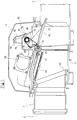
- FIG. 1 shows an embodiment of the Backflow valve device according to the invention.
- a Cleaning pipe 1 has an opening 2 for the connection an inlet pipe, an opening 3 for connecting a Drain pipe and a cover 4.
- Such Cleaning pipes are for example in the Pipeline, e.g. used in the basement.
- At the opening 2 of the cleaning tube 1 closes in In this case, an inflow through which the waste water enters Cleaning pipe enters and exits through opening 3, to which a drain pipe is connected.
- Cleaning pipe 1 a substantially U-shaped Base body 5, in which an operating lock 40 and an emergency seal 70 are used. After removing the Cover 4 and removal of the operating lock 40 and the emergency lock 70 delimits the base body 5 an open-top cleaning shaft that gives access of the pipe system for cleaning work.
- the operating lock has an operating lock flap 41, which has an operating lock actuator 50 can be pivoted.
- the Operating lock actuator 50 has one Servomotor on, which is a function of signals Backflow detection device the service shutter 41 stops in a first operating position, in the Drainage of waste water is possible if based on the signals the backflow detection device is recognized that no Back pressure is present. This position of Operating closure flap 41 is shown in FIGS. 1 to 3 shown.
- the backflow detection device recognizes this Malfunction and gives appropriate signals to the Operating lock actuator 50 from.
- the operation shutter actuator moves 50 via the servomotor Operation shutter 41 in the second Operating position in which the operating closure flap 41 fits tightly against a sealing seat 42 and thereby the Waste water pipe closed.
- the emergency closure 70 has an emergency closure flap 71, by a pivot shaft 72 in a pivot bearing 73 is stored. On the emergency flap 71 is a Guide web 74 integrally formed with a guide track 75.
- the emergency lock is operated using a Actuator 80, which with a manual control lever 90 in Connection is established. Both the manual control lever 90 and the actuating element 80 are also above a predetermined one Angular range pivotable about an axis of rotation 91, wherein the actuating element 80 via a square recess 81 positively connected to the manual control lever 90 is and a predetermined angular position to the Hand control lever 90 takes.
- Figures 4 and 5 show a first embodiment of the Actuating element 80 and the associated guideway 75.
- This actuating element 80 has two side walls 82a, 82b on.
- Side wall 82b shown partially cut to the View of a locking pin 83 to release the one has an approximately semicircular cross section.
- Locking pin 83 is on both side walls 82a, 82b molded and connects them together.
- Locking pins 83 are on each side wall 82a, 82b each formed a locking pin 84a, 84b.
- the Locking pins 84a, 84b have a round cross section and a common central axis.
- the distance of the Locking pin 84a, 84b to each other is dimensioned so that the Guide bar can pass through the locking pin, i.e. the thickness of the guide web 74 is less than that Distance of the end faces of the locking pins 84a, 84b.
- the guideway 75 has two opposing curvatures on a first section 75a, a second Section 75b and a third section 75c from each other delimit. This results in an approximately S-shaped Course of the continuous top 76 and the two opposite and through the guide web 74 separate undersides 77a, 77b of the Track 75.
- the manual operating lever 90 is between the first and the second end position lying middle position occupies, which is shown in Fig. 3, is Emergency flap 70 between one with a solid Lines shown closed position and one in Dashed lines shown open position freely movable and can move in between these positions Swing back and forth in the direction of arrow A.
- the middle position of the manual control lever 90 can Guide bar in the swivel area between the two End positions freely between the side walls 82a, 82b of the Actuating element 80 pass through without the Locking pin 83 with the top 76 of the guideway 75 and the locking pins 84a, 84b with the undersides 77a, 77b the guideway 75 come into contact.
- the manual operating lever 90 is one end Connected spring element 92, at the other end one Latch 93 is formed.
- the Manual operating lever 90 runs the latch 93 over the Surface of a molded part 94 which is shaped such that the manual operating lever 90 in the first and second End position and in the intermediate position Middle position is fixable. This will ensured that the manual operating lever 90 and so the actuator 80 in the desired position remain and the emergency seal actually the occupies the desired operating position.
- Fixing the manual control lever 90 in the two End positions or the middle position is thereby causes the spring element 92 and the molded part 94 so trained and assigned to each other that a Displacement of the manual control lever 90 from a of these three positions a deformation of the spring element 92 requires.
- the one for the deformation of the spring element 92 The force required is such that, on the one hand, the Operating forces of the manual operating lever 90 are not too high lie and on the other hand a reliable fixation in the two end positions and the middle position is guaranteed.
- FIGS Figures 6 and 7 is a modified Embodiment of an emergency seal 170 shown.
- the embodiment of the emergency closure 70 according to FIGS Figures 4 and 5 corresponding components are with the provided with the same reference numerals, only by the number 100 increased.
- the emergency lock 170 corresponds to the Figures 6 and 7 essentially according to the emergency closure 70 Figures 4 and 5.
- the pivot bearing 173 for receiving the Swivel shaft 172 a greater distance from each other have as the pivot bearing 73 of the above described first embodiment of the emergency seal 70. This ensures a particularly stable storage of the Emergency flap 171 reached.
- Locking pins 184a, 184b on the outer sides of the side walls 182a, 182b of the actuating element 180 are integrally formed. This results in greater freedom of design in the construction of the guideway 175, whose Top 176 in the third section 175c Interact with the locking pin 183, which in this Embodiment has a circular cross section, closing the emergency flap in the second Must ensure the operational position of the emergency lock, their passage through the two side walls 182a and 182b due to the external locking pins 184a, 184b is relieved, however.
- the locking pins 184a, 184b engage in the first Operating position of the emergency lock 171 in corresponding trained guide pieces 188a, 188b, to both Sides of the guide bar 174 on the flap 171 are molded.
- the emergency lock 170 corresponds to 6 and 7 the emergency closure 70 according to the figures 4 and 5.
Landscapes
- Health & Medical Sciences (AREA)
- Life Sciences & Earth Sciences (AREA)
- Engineering & Computer Science (AREA)
- Hydrology & Water Resources (AREA)
- Public Health (AREA)
- Water Supply & Treatment (AREA)
- Sewage (AREA)
- Mechanically-Actuated Valves (AREA)
- Revetment (AREA)
- Indication Of The Valve Opening Or Closing Status (AREA)
- Fluid-Driven Valves (AREA)
- Check Valves (AREA)
Applications Claiming Priority (2)
| Application Number | Priority Date | Filing Date | Title |
|---|---|---|---|
| DE19757743 | 1997-12-23 | ||
| DE19757743A DE19757743C1 (de) | 1997-12-23 | 1997-12-23 | Rückstauverschlußvorrichtung |
Publications (3)
| Publication Number | Publication Date |
|---|---|
| EP0926301A2 true EP0926301A2 (fr) | 1999-06-30 |
| EP0926301A3 EP0926301A3 (fr) | 1999-11-17 |
| EP0926301B1 EP0926301B1 (fr) | 2004-03-31 |
Family
ID=7853305
Family Applications (1)
| Application Number | Title | Priority Date | Filing Date |
|---|---|---|---|
| EP98122778A Expired - Lifetime EP0926301B1 (fr) | 1997-12-23 | 1998-12-01 | Clapet anti-refoulement |
Country Status (3)
| Country | Link |
|---|---|
| EP (1) | EP0926301B1 (fr) |
| AT (1) | ATE263291T1 (fr) |
| DE (1) | DE19757743C1 (fr) |
Cited By (4)
| Publication number | Priority date | Publication date | Assignee | Title |
|---|---|---|---|---|
| GB2373258A (en) * | 2001-03-17 | 2002-09-18 | Ray Wolfenden | Floodwater/sewerage protection for buildings |
| EP1548194A1 (fr) * | 2003-12-22 | 2005-06-29 | HL Hutterer & Lechner GmbH | Dispositif de nettoyage de pipeline |
| EP1679407A1 (fr) * | 2005-01-05 | 2006-07-12 | Aco Severin Ahlmann Gmbh & Co. Kg | Fermeture anti-refoulement |
| DE102010036916A1 (de) | 2010-08-09 | 2012-02-09 | Aco Severin Ahlmann Gmbh & Co. Kg | Rückstausperre für eine Abwasserleitung und Verfahren zum Betreiben einer derartigen Rückstausperre |
Families Citing this family (7)
| Publication number | Priority date | Publication date | Assignee | Title |
|---|---|---|---|---|
| DE19910254C2 (de) * | 1999-03-08 | 2003-01-02 | Kessel Gmbh | Hebeanlage für Abwasser |
| EP2154300B1 (fr) | 2008-08-14 | 2011-12-28 | Kessel AG | Station d'eaux usées |
| DE202008015822U1 (de) * | 2008-12-01 | 2010-02-11 | Abu-Plast Kunststoffbetriebe Gmbh | Sperrvorrichtung einer Rohrleitung, insbesondere einer WC-Abwasserleitung |
| NL2011130C2 (nl) * | 2013-07-10 | 2015-01-13 | Dennis Veldhuizen | Werkwijze voor het tijdelijk afsluiten van een middels een rooster afgedekte goot van een verhard stuk aardoppervlak; alsmede een afsluitorgaan voor een goot. |
| EP2868823B1 (fr) * | 2013-10-31 | 2018-12-05 | Nordisk Innovation ApS | Barrière de vermine et méthode d'opération d'une telle |
| CN107429510B (zh) * | 2015-03-03 | 2020-07-07 | 卡伦·伊丽莎白·达姆高·詹森 | 组合式止回阀和灭鼠器 |
| EP4506517A1 (fr) | 2023-08-07 | 2025-02-12 | Hauraton GmbH & Co. KG | Dispositif de fermeture pour une gouttiere |
Citations (1)
| Publication number | Priority date | Publication date | Assignee | Title |
|---|---|---|---|---|
| EP0307698A1 (fr) | 1987-09-17 | 1989-03-22 | Bernhard Kessel | Trousse comportant un tuyau de nettoyage pour des conduites d'égout continue |
Family Cites Families (2)
| Publication number | Priority date | Publication date | Assignee | Title |
|---|---|---|---|---|
| DE8712537U1 (de) * | 1987-09-17 | 1987-11-05 | Kessel, Bernhard, 8071 Lenting | Reinigungsrohr für druchgehende Abwasser-Rohrleitungen |
| DE9413322U1 (de) * | 1994-08-18 | 1995-12-21 | Fa. Franz Viegener Ii, 57439 Attendorn | Rückstauvorrichtung |
-
1997
- 1997-12-23 DE DE19757743A patent/DE19757743C1/de not_active Expired - Lifetime
-
1998
- 1998-12-01 AT AT98122778T patent/ATE263291T1/de active
- 1998-12-01 EP EP98122778A patent/EP0926301B1/fr not_active Expired - Lifetime
Patent Citations (1)
| Publication number | Priority date | Publication date | Assignee | Title |
|---|---|---|---|---|
| EP0307698A1 (fr) | 1987-09-17 | 1989-03-22 | Bernhard Kessel | Trousse comportant un tuyau de nettoyage pour des conduites d'égout continue |
Cited By (6)
| Publication number | Priority date | Publication date | Assignee | Title |
|---|---|---|---|---|
| GB2373258A (en) * | 2001-03-17 | 2002-09-18 | Ray Wolfenden | Floodwater/sewerage protection for buildings |
| GB2373258B (en) * | 2001-03-17 | 2003-11-19 | Ray Wolfenden | Floodwater/sewage protection for buildings |
| EP1548194A1 (fr) * | 2003-12-22 | 2005-06-29 | HL Hutterer & Lechner GmbH | Dispositif de nettoyage de pipeline |
| EP1679407A1 (fr) * | 2005-01-05 | 2006-07-12 | Aco Severin Ahlmann Gmbh & Co. Kg | Fermeture anti-refoulement |
| DE102010036916A1 (de) | 2010-08-09 | 2012-02-09 | Aco Severin Ahlmann Gmbh & Co. Kg | Rückstausperre für eine Abwasserleitung und Verfahren zum Betreiben einer derartigen Rückstausperre |
| DE102010036916B4 (de) * | 2010-08-09 | 2015-04-09 | Aco Severin Ahlmann Gmbh & Co. Kg | Rückstausperre für eine Abwasserleitung und Verfahren zum Betreiben einer derartigen Rückstausperre |
Also Published As
| Publication number | Publication date |
|---|---|
| DE19757743C1 (de) | 1999-02-11 |
| EP0926301B1 (fr) | 2004-03-31 |
| ATE263291T1 (de) | 2004-04-15 |
| EP0926301A3 (fr) | 1999-11-17 |
Similar Documents
| Publication | Publication Date | Title |
|---|---|---|
| DE69824615T2 (de) | Verbesserter tropfbewässerungsauslass | |
| DE19757743C1 (de) | Rückstauverschlußvorrichtung | |
| EP0122323A1 (fr) | Soupape à double siège avec deux têtes de soupape | |
| DE4226685C5 (de) | Überlaufarmatur für eine Bade- oder Duschwanne | |
| EP0137154B1 (fr) | Robinet à voies multiples | |
| EP0307698B1 (fr) | Trousse comportant un tuyau de nettoyage pour des conduites d'égout continue | |
| DE19715905B4 (de) | Vorrichtung zum Absperren des Zu- oder Ablaufrohres eines Leichtflüssigkeitsabscheiders | |
| EP1035262B1 (fr) | Dispositif de levage d'eaux usées | |
| DE2809825C2 (de) | Rückstauverschluß für Abwasserleitungen | |
| EP0469361A1 (fr) | Bouche d'écoulement | |
| EP3578723A1 (fr) | Fermeture anti-odeurs pour une évacuation d'eau ainsi qu'une évacuation d'eau pourvue d'une telle fermeture anti-odeurs | |
| DE8524288U1 (de) | Membran-Absperrventil für Unterdruck-Abwasserleitungen | |
| DE3046253C2 (de) | Rückstauverschluß | |
| EP0634529B1 (fr) | Disconnecteur de tuyau | |
| EP3851596B1 (fr) | Système de rinçage des toilettes doté d'une fonction de réglage de la vitesse de rinçage | |
| DE2452786C2 (de) | Rückstau- und Schließventil für Flüssigkeitsabläufe | |
| DE29519146U1 (de) | Füllvorrichtung für Batteriezellen | |
| DE29923799U1 (de) | Doppelsitzventil mit spülfähiger Ventilstangendurchführung am Ventilgehäuse | |
| DE202005003263U1 (de) | Schieberventil | |
| DE8712537U1 (de) | Reinigungsrohr für druchgehende Abwasser-Rohrleitungen | |
| DE202025103343U1 (de) | Ablaufgarnitur für Spülbecken | |
| DE3306968A1 (de) | Rueckstauverschluss fuer entwaesserungsleitungen | |
| DE29612776U1 (de) | Vorrichtung zum Schließen einer Entlastungsöffnung eines Gehäuses eines Druckmeßgerätes sowie zum Belüften des Gehäuses | |
| DE2522426C3 (de) | Rückstau-Doppelverschluli | |
| DE19858515A1 (de) | Hydrant mit verschließbarem Standrohranschluß |
Legal Events
| Date | Code | Title | Description |
|---|---|---|---|
| PUAI | Public reference made under article 153(3) epc to a published international application that has entered the european phase |
Free format text: ORIGINAL CODE: 0009012 |
|
| AK | Designated contracting states |
Kind code of ref document: A2 Designated state(s): AT CH FR GB IT LI NL |
|
| AX | Request for extension of the european patent |
Free format text: AL;LT;LV;MK;RO;SI |
|
| PUAL | Search report despatched |
Free format text: ORIGINAL CODE: 0009013 |
|
| AK | Designated contracting states |
Kind code of ref document: A3 Designated state(s): AT BE CH CY DE DK ES FI FR GB GR IE IT LI LU MC NL PT SE |
|
| AX | Request for extension of the european patent |
Free format text: AL;LT;LV;MK;RO;SI |
|
| RAP1 | Party data changed (applicant data changed or rights of an application transferred) |
Owner name: KESSEL GMBH |
|
| RIN1 | Information on inventor provided before grant (corrected) |
Inventor name: KESSEL GMBH |
|
| 17P | Request for examination filed |
Effective date: 19991127 |
|
| AKX | Designation fees paid |
Free format text: AT CH FR GB IT LI NL |
|
| REG | Reference to a national code |
Ref country code: DE Ref legal event code: 8566 |
|
| REG | Reference to a national code |
Ref country code: IE Ref legal event code: FG4D |
|
| 17Q | First examination report despatched |
Effective date: 20030310 |
|
| GRAP | Despatch of communication of intention to grant a patent |
Free format text: ORIGINAL CODE: EPIDOSNIGR1 |
|
| RIN1 | Information on inventor provided before grant (corrected) |
Inventor name: KESSEL, BERNHARD |
|
| GRAS | Grant fee paid |
Free format text: ORIGINAL CODE: EPIDOSNIGR3 |
|
| GRAA | (expected) grant |
Free format text: ORIGINAL CODE: 0009210 |
|
| AK | Designated contracting states |
Kind code of ref document: B1 Designated state(s): AT CH FR GB IT LI NL |
|
| REG | Reference to a national code |
Ref country code: GB Ref legal event code: FG4D Free format text: NOT ENGLISH Ref country code: CH Ref legal event code: EP |
|
| GBT | Gb: translation of ep patent filed (gb section 77(6)(a)/1977) |
Effective date: 20040719 |
|
| REG | Reference to a national code |
Ref country code: CH Ref legal event code: NV Representative=s name: ZIMMERLI, WAGNER & PARTNER AG |
|
| ET | Fr: translation filed | ||
| PLBE | No opposition filed within time limit |
Free format text: ORIGINAL CODE: 0009261 |
|
| STAA | Information on the status of an ep patent application or granted ep patent |
Free format text: STATUS: NO OPPOSITION FILED WITHIN TIME LIMIT |
|
| 26N | No opposition filed |
Effective date: 20050104 |
|
| PG25 | Lapsed in a contracting state [announced via postgrant information from national office to epo] |
Ref country code: IT Free format text: LAPSE BECAUSE OF NON-PAYMENT OF DUE FEES;WARNING: LAPSES OF ITALIAN PATENTS WITH EFFECTIVE DATE BEFORE 2007 MAY HAVE OCCURRED AT ANY TIME BEFORE 2007. THE CORRECT EFFECTIVE DATE MAY BE DIFFERENT FROM THE ONE RECORDED. Effective date: 20051201 |
|
| REG | Reference to a national code |
Ref country code: CH Ref legal event code: PFA Owner name: KESSEL GMBH Free format text: KESSEL GMBH#BAHNHOFSTRASSE 31#85101 LENTING (DE) -TRANSFER TO- KESSEL GMBH#BAHNHOFSTRASSE 31#85101 LENTING (DE) |
|
| PGRI | Patent reinstated in contracting state [announced from national office to epo] |
Ref country code: IT Effective date: 20091201 |
|
| REG | Reference to a national code |
Ref country code: CH Ref legal event code: PFA Owner name: KESSEL AG Free format text: KESSEL GMBH#BAHNHOFSTRASSE 31#85101 LENTING (DE) -TRANSFER TO- KESSEL AG#BAHNHOFSTRASSE 31#85101 LENTING (DE) |
|
| REG | Reference to a national code |
Ref country code: FR Ref legal event code: CJ Ref country code: FR Ref legal event code: CD |
|
| REG | Reference to a national code |
Ref country code: NL Ref legal event code: TD Effective date: 20110325 |
|
| REG | Reference to a national code |
Ref country code: GB Ref legal event code: 732E Free format text: REGISTERED BETWEEN 20110324 AND 20110330 |
|
| REG | Reference to a national code |
Ref country code: CH Ref legal event code: NV Representative=s name: WAGNER PATENT AG, CH |
|
| REG | Reference to a national code |
Ref country code: FR Ref legal event code: PLFP Year of fee payment: 18 |
|
| PGFP | Annual fee paid to national office [announced via postgrant information from national office to epo] |
Ref country code: CH Payment date: 20151221 Year of fee payment: 18 Ref country code: GB Payment date: 20151221 Year of fee payment: 18 |
|
| PGFP | Annual fee paid to national office [announced via postgrant information from national office to epo] |
Ref country code: FR Payment date: 20151221 Year of fee payment: 18 Ref country code: NL Payment date: 20151217 Year of fee payment: 18 |
|
| PGFP | Annual fee paid to national office [announced via postgrant information from national office to epo] |
Ref country code: IT Payment date: 20151230 Year of fee payment: 18 |
|
| REG | Reference to a national code |
Ref country code: CH Ref legal event code: PL |
|
| REG | Reference to a national code |
Ref country code: NL Ref legal event code: MM Effective date: 20170101 |
|
| GBPC | Gb: european patent ceased through non-payment of renewal fee |
Effective date: 20161201 |
|
| PG25 | Lapsed in a contracting state [announced via postgrant information from national office to epo] |
Ref country code: NL Free format text: LAPSE BECAUSE OF NON-PAYMENT OF DUE FEES Effective date: 20170101 |
|
| REG | Reference to a national code |
Ref country code: FR Ref legal event code: ST Effective date: 20170831 |
|
| PG25 | Lapsed in a contracting state [announced via postgrant information from national office to epo] |
Ref country code: LI Free format text: LAPSE BECAUSE OF NON-PAYMENT OF DUE FEES Effective date: 20161231 Ref country code: IT Free format text: LAPSE BECAUSE OF NON-PAYMENT OF DUE FEES Effective date: 20161201 Ref country code: FR Free format text: LAPSE BECAUSE OF NON-PAYMENT OF DUE FEES Effective date: 20170102 Ref country code: CH Free format text: LAPSE BECAUSE OF NON-PAYMENT OF DUE FEES Effective date: 20161231 |
|
| PG25 | Lapsed in a contracting state [announced via postgrant information from national office to epo] |
Ref country code: GB Free format text: LAPSE BECAUSE OF NON-PAYMENT OF DUE FEES Effective date: 20161201 |
|
| PGFP | Annual fee paid to national office [announced via postgrant information from national office to epo] |
Ref country code: AT Payment date: 20171221 Year of fee payment: 20 |
|
| REG | Reference to a national code |
Ref country code: AT Ref legal event code: MK07 Ref document number: 263291 Country of ref document: AT Kind code of ref document: T Effective date: 20181201 |