EP0926302A2 - Verbindungselement für Isoliermatten - Google Patents
Verbindungselement für Isoliermatten Download PDFInfo
- Publication number
- EP0926302A2 EP0926302A2 EP98123617A EP98123617A EP0926302A2 EP 0926302 A2 EP0926302 A2 EP 0926302A2 EP 98123617 A EP98123617 A EP 98123617A EP 98123617 A EP98123617 A EP 98123617A EP 0926302 A2 EP0926302 A2 EP 0926302A2
- Authority
- EP
- European Patent Office
- Prior art keywords
- dowel
- connecting element
- recesses
- element according
- mat
- Prior art date
- Legal status (The legal status is an assumption and is not a legal conclusion. Google has not performed a legal analysis and makes no representation as to the accuracy of the status listed.)
- Withdrawn
Links
Images
Classifications
-
- F—MECHANICAL ENGINEERING; LIGHTING; HEATING; WEAPONS; BLASTING
- F16—ENGINEERING ELEMENTS AND UNITS; GENERAL MEASURES FOR PRODUCING AND MAINTAINING EFFECTIVE FUNCTIONING OF MACHINES OR INSTALLATIONS; THERMAL INSULATION IN GENERAL
- F16B—DEVICES FOR FASTENING OR SECURING CONSTRUCTIONAL ELEMENTS OR MACHINE PARTS TOGETHER, e.g. NAILS, BOLTS, CIRCLIPS, CLAMPS, CLIPS OR WEDGES; JOINTS OR JOINTING
- F16B21/00—Means for preventing relative axial movement of a pin, spigot, shaft or the like and a member surrounding it; Stud-and-socket releasable fastenings
-
- E—FIXED CONSTRUCTIONS
- E04—BUILDING
- E04B—GENERAL BUILDING CONSTRUCTIONS; WALLS, e.g. PARTITIONS; ROOFS; FLOORS; CEILINGS; INSULATION OR OTHER PROTECTION OF BUILDINGS
- E04B1/00—Constructions in general; Structures which are not restricted either to walls, e.g. partitions, or floors or ceilings or roofs
- E04B1/62—Insulation or other protection; Elements or use of specified material therefor
- E04B1/74—Heat, sound or noise insulation, absorption, or reflection; Other building methods affording favourable thermal or acoustical conditions, e.g. accumulating of heat within walls
- E04B1/76—Heat, sound or noise insulation, absorption, or reflection; Other building methods affording favourable thermal or acoustical conditions, e.g. accumulating of heat within walls specifically with respect to heat only
- E04B1/762—Exterior insulation of exterior walls
- E04B1/7629—Details of the mechanical connection of the insulation to the wall
- E04B1/7633—Dowels with enlarged insulation retaining head
Definitions
- the invention relates to a connecting element according to the genus of Main claim.
- double-layer insulation mats are placed on the walls appropriate.
- the lower insulation mat is traditionally anchored in the subsurface and the second upper mat is only attached to the basic insulation. It is necessary that the attachment until the weather shell is attached in addition to the lower dead weight also the occurring ones Absorbs wind suction forces.
- they are often corkscrew-like Wires with the help of electric screwdrivers and a suitable one Setting tool through the front paint into the basic insulation turned in.
- the holding values of these wires are relatively low, so not always the wind suction forces can be absorbed.
- a wire made of stainless steel can be used. This makes the Attachment.
- the invention has for its object a cost-effective connecting element to create insulation mats that can be easily set and allows a good fastening of insulating mats.
- the dowel has recesses in the front area which can be closed with the help of movable flaps the dowel is first closed when piercing the mat, because the Insert flaps on the dowel shaft. Only when the expansion agent is pressed out the expanding foam becomes from the cartridge into the dowel emerge through the recesses and through the generating pressure on the Fold them into an almost vertical position. This leads to, that mechanical interlocking is created in the mat base. It swells the foam between the fiber bundles and after curing creates a good and economic anchoring.
- the attachment takes place in such a way that first the dowel over the front Mat is put through. The openings in the dowel are closed. Then the cartridge cannula is inserted into the dowel plate and that Expansion agent sprayed out. The strongly expanding foam passes through the Openings and places the movable flaps almost perpendicular to the longitudinal axis of the dowel on. The flaps are set up mechanically Interlocking in the mat base. In addition, the dowel plate is against Surface of the front mat pulled out because of the expanding agent presses the open flaps. At the same time, the foam swells between the individual Fiber bundle of the insulating mat and binds a thread-like lump, which creates a secure anchor after the foam has hardened.
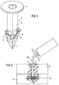
- the dowel 1 shown in Figure 1 consists of a shaft 9 and a plate 2.
- the dowel is provided with a tip 7 in the front area.
- recesses 5, 6 made with the help of movable Flaps 3, 4 are closed.
- the cartridge cannula is inserted into the dowel and the expansion agent is sprayed out.
- the strongly expanding foam 13 occurs through the recesses 5, 6 in the dowel shaft 9 and sets the flaps perpendicular to the dowel axis.
- the foam 13 swells between the individual Fiber bundle of the rear mat and hardens, as shown in FIG. 2, out.
Landscapes
- Engineering & Computer Science (AREA)
- Physics & Mathematics (AREA)
- Architecture (AREA)
- Electromagnetism (AREA)
- Acoustics & Sound (AREA)
- General Engineering & Computer Science (AREA)
- Civil Engineering (AREA)
- Structural Engineering (AREA)
- Mechanical Engineering (AREA)
- Joining Of Building Structures In Genera (AREA)
- Conveying And Assembling Of Building Elements In Situ (AREA)
- Microwave Amplifiers (AREA)
- Design And Manufacture Of Integrated Circuits (AREA)
Abstract
Description
- Figur 1
- den erfindungsgemäßen Dübel in Sicht
- Figur 2
- zwei, mit Hilfe des in Figur 1 dargestellten Dübels, verbundene Matten
Claims (5)
- Verbindungselement zum Verbinden von Isoliermatten untereinander, das aus einem Dübel mit Schaft und Teller, sowie einem Expansionsmittelbesteht, dadurch gekennzeichnet, daß der Dübel (1) mit Ausnehmungen (5, 6), die durch die beweglichen Klappen (3, 4) verschlossen sind, versehen ist, und daß das expansionsfähige Mittel durch die Ausnehmungen (5, 6) in die Isoliermatten (15) gelangt.
- Verbindungselement nach Anspruch 1, dadurch gekennzeichnet, daß die Ausnehmungen (5,6) über der Dübelspitze (7) angeordnet sind.
- Verbindungselement nach Anspruch 1, dadurch gekennzeichnet, daß der Dübel aus Kunststoff hergestellt ist.
- Verbindungselement nach Anspruch 1, dadurch gekennzeichnet, daß als expansionsfähiges Mittel Bauschäume eingesetzt sind.
- Verbindungselement nach Anspruch 1, dadurch gekennzeichnet, daß die Länge des Schaftes so gewählt ist, daß die Klappen (3, 4) und Ausnehmungen (5, 6) hinter der Dübelspitze (7) mittig innerhalb der hinteren Matte liegen.
Applications Claiming Priority (2)
| Application Number | Priority Date | Filing Date | Title |
|---|---|---|---|
| DE29722726U | 1997-12-23 | ||
| DE29722726U DE29722726U1 (de) | 1997-12-23 | 1997-12-23 | Verbindungselement für Isoliermatten |
Publications (2)
| Publication Number | Publication Date |
|---|---|
| EP0926302A2 true EP0926302A2 (de) | 1999-06-30 |
| EP0926302A3 EP0926302A3 (de) | 2000-11-08 |
Family
ID=8050407
Family Applications (1)
| Application Number | Title | Priority Date | Filing Date |
|---|---|---|---|
| EP98123617A Withdrawn EP0926302A3 (de) | 1997-12-23 | 1998-12-10 | Verbindungselement für Isoliermatten |
Country Status (2)
| Country | Link |
|---|---|
| EP (1) | EP0926302A3 (de) |
| DE (1) | DE29722726U1 (de) |
Cited By (12)
| Publication number | Priority date | Publication date | Assignee | Title |
|---|---|---|---|---|
| WO2002061217A1 (en) * | 2001-02-01 | 2002-08-08 | Rockwool International A/S | A method of joining two or more units of insulating material |
| DK202370574A1 (en) * | 2023-03-17 | 2024-11-11 | Lear Corp | Method and apparatus for attaching a fastener to a body of extruded polymer filaments |
| US12269384B2 (en) | 2021-03-31 | 2025-04-08 | Lear Corporation | Seat support |
| US12286045B2 (en) | 2021-12-02 | 2025-04-29 | Lear Corporation | Vehicle seating system and method for producing same |
| US12286044B2 (en) | 2023-05-12 | 2025-04-29 | Lear Corporation | Method and apparatus for producing a vehicle interior component |
| US12319183B2 (en) | 2021-03-31 | 2025-06-03 | Lear Corporation | Seat support |
| US12325168B2 (en) | 2021-12-20 | 2025-06-10 | Lear Corporation | System and method of making a mesh cushion |
| US12325624B2 (en) | 2023-03-06 | 2025-06-10 | Lear Corporation | Seat assembly, cushion, and tool and method of forming |
| US12384094B2 (en) | 2022-03-08 | 2025-08-12 | Lear Corporation | Method for producing a vehicle interior component |
| US12454111B2 (en) | 2022-05-11 | 2025-10-28 | Lear Corporation | Tool to manufacture a cushion |
| US12479143B2 (en) | 2021-12-20 | 2025-11-25 | Lear Corporation | System and method of making a mesh cushion |
| US12509343B2 (en) | 2023-02-28 | 2025-12-30 | Lear Corporation | Automated trench manufacturing and assembly for attaching trim covers to a cushion assembly |
Family Cites Families (6)
| Publication number | Priority date | Publication date | Assignee | Title |
|---|---|---|---|---|
| CH426380A (de) * | 1963-01-28 | 1966-12-15 | Camporese Marsilio Ing Dr | Expansionsstift |
| US4094054A (en) * | 1974-10-03 | 1978-06-13 | Artur Fischer | Method of securing an object to a low-strength support structure |
| DE3116101C2 (de) * | 1981-04-23 | 1983-04-21 | Thermotect-Brandschutzmaterial GmbH, 3181 Jembke | Schraubelement zum Verbinden halbstarrer Matten |
| DE3225051A1 (de) * | 1982-07-05 | 1984-01-05 | Hilti AG, 9494 Schaan | Duebel fuer hohlraeume aufweisende aufnahmematerialien |
| DE3248143A1 (de) * | 1982-12-27 | 1984-06-28 | Hilti Ag, Schaan | Durch aushaertbare masse verfestigbarer duebel |
| DE3345964A1 (de) * | 1983-12-20 | 1985-06-27 | Kaefer Isoliertechnik Gmbh & Co Kg, 2800 Bremen | Element fuer daemmungen gegen waerme und schall |
-
1997
- 1997-12-23 DE DE29722726U patent/DE29722726U1/de not_active Expired - Lifetime
-
1998
- 1998-12-10 EP EP98123617A patent/EP0926302A3/de not_active Withdrawn
Cited By (13)
| Publication number | Priority date | Publication date | Assignee | Title |
|---|---|---|---|---|
| WO2002061217A1 (en) * | 2001-02-01 | 2002-08-08 | Rockwool International A/S | A method of joining two or more units of insulating material |
| US12319183B2 (en) | 2021-03-31 | 2025-06-03 | Lear Corporation | Seat support |
| US12269384B2 (en) | 2021-03-31 | 2025-04-08 | Lear Corporation | Seat support |
| US12286045B2 (en) | 2021-12-02 | 2025-04-29 | Lear Corporation | Vehicle seating system and method for producing same |
| US12325168B2 (en) | 2021-12-20 | 2025-06-10 | Lear Corporation | System and method of making a mesh cushion |
| US12479143B2 (en) | 2021-12-20 | 2025-11-25 | Lear Corporation | System and method of making a mesh cushion |
| US12384094B2 (en) | 2022-03-08 | 2025-08-12 | Lear Corporation | Method for producing a vehicle interior component |
| US12454111B2 (en) | 2022-05-11 | 2025-10-28 | Lear Corporation | Tool to manufacture a cushion |
| US12509343B2 (en) | 2023-02-28 | 2025-12-30 | Lear Corporation | Automated trench manufacturing and assembly for attaching trim covers to a cushion assembly |
| US12325624B2 (en) | 2023-03-06 | 2025-06-10 | Lear Corporation | Seat assembly, cushion, and tool and method of forming |
| DK182002B1 (en) * | 2023-03-17 | 2025-05-20 | Lear Corp | METHOD AND APPARATUS FOR ATTACHING A FIXING DEVICE TO A BODY OF EXTRUDED POLYMER FILAMENTS |
| DK202370574A1 (en) * | 2023-03-17 | 2024-11-11 | Lear Corp | Method and apparatus for attaching a fastener to a body of extruded polymer filaments |
| US12286044B2 (en) | 2023-05-12 | 2025-04-29 | Lear Corporation | Method and apparatus for producing a vehicle interior component |
Also Published As
| Publication number | Publication date |
|---|---|
| EP0926302A3 (de) | 2000-11-08 |
| DE29722726U1 (de) | 1999-04-22 |
Similar Documents
| Publication | Publication Date | Title |
|---|---|---|
| DE69516864T2 (de) | Hochisolierende verbindungsstäbe und verfahren zu ihrer herstellung und ihrer anwendung in hochisolierten zusammengesetzten wänden | |
| DE2008402A1 (de) | Verbundanker | |
| EP0926302A2 (de) | Verbindungselement für Isoliermatten | |
| DE19539041A1 (de) | Befestigungselement | |
| EP2067907A1 (de) | Verfahren und Abstandshalter zum Befestigen von Bewehrungsmatten | |
| EP2215317B2 (de) | Dämmstoffhalter und verfahren zum befestigen einer dämmstoffplatte | |
| DE2158129C3 (de) | Fassadenwand mit tragenden Stützen | |
| EP1541881B1 (de) | Spreizdübel | |
| EP2055845A2 (de) | Kragplattenanschlusselement | |
| DE102007048802A1 (de) | Befestigungselement | |
| EP1505218B1 (de) | Wärmedämmverbundsystem | |
| DE4006691C2 (de) | Stahltürzarge mit Schwellenprofil | |
| EP1715130B1 (de) | Rahmenelement, insbesondere Sicherheitszarge | |
| DE10228255C1 (de) | Fassadendose | |
| DE4436808A1 (de) | Verbindungselement | |
| DE202021104302U1 (de) | Trägerplatte zur Aufnahme von Befestigungselementen an Abstandhaltern | |
| DE10214229C5 (de) | Schraubbuchse und Verfahren zur Herstellung eines Verkleidungselements und mit Schraubbuchsen versehenes Verkleidungselement | |
| DE3834731A1 (de) | Vorrichtung zur verankerung oder verbindung von betonbewehrungsstaeben sowie verfahren zum herstellen derselben | |
| DE2158627C2 (de) | Vorrichtung zur druck und zug festen Verankerung von vorgehängten Fas sadenplatten | |
| EP2331767B1 (de) | Modulares befestigungselement und werkzeug zur verschraubung dieses befestigungselementes | |
| DE102004043581A1 (de) | Bauteilesatz aus wenigstens einer Sprosse und wenigstens zwei Sprossenendstücken zum Einbauen in eine Isolierglasscheibe | |
| DE202004017181U1 (de) | Verbundprofil mit thermischer Trennung und fixiertem Schalelement | |
| DE102016125008A1 (de) | Holz-Beton-Verbinder und Befestigungsanordnung | |
| DE60109766T2 (de) | Mauerwerksanker | |
| DE3634993C2 (de) |
Legal Events
| Date | Code | Title | Description |
|---|---|---|---|
| PUAI | Public reference made under article 153(3) epc to a published international application that has entered the european phase |
Free format text: ORIGINAL CODE: 0009012 |
|
| AK | Designated contracting states |
Kind code of ref document: A2 Designated state(s): DE ES FR GB IT |
|
| AX | Request for extension of the european patent |
Free format text: AL;LT;LV;MK;RO;SI |
|
| PUAL | Search report despatched |
Free format text: ORIGINAL CODE: 0009013 |
|
| AK | Designated contracting states |
Kind code of ref document: A3 Designated state(s): AT BE CH CY DE DK ES FI FR GB GR IE IT LI LU MC NL PT SE |
|
| AX | Request for extension of the european patent |
Free format text: AL;LT;LV;MK;RO;SI |
|
| RIC1 | Information provided on ipc code assigned before grant |
Free format text: 7E 04B 1/76 A, 7F 16B 21/00 B |
|
| 17P | Request for examination filed |
Effective date: 20001219 |
|
| AKX | Designation fees paid |
Free format text: DE ES FR GB IT |
|
| RAP1 | Party data changed (applicant data changed or rights of an application transferred) |
Owner name: FISCHERWERKE ARTUR FISCHER GMBH & CO. KG |
|
| RAP1 | Party data changed (applicant data changed or rights of an application transferred) |
Owner name: FISCHERWERKE ARTUR FISCHER GMBH & CO. KG |
|
| 17Q | First examination report despatched |
Effective date: 20041207 |
|
| STAA | Information on the status of an ep patent application or granted ep patent |
Free format text: STATUS: THE APPLICATION IS DEEMED TO BE WITHDRAWN |
|
| 18D | Application deemed to be withdrawn |
Effective date: 20050419 |