EP0926323B1 - Chambre de vapeur pour une turbine à gaz refroidi par vapeur - Google Patents
Chambre de vapeur pour une turbine à gaz refroidi par vapeur Download PDFInfo
- Publication number
- EP0926323B1 EP0926323B1 EP98123914A EP98123914A EP0926323B1 EP 0926323 B1 EP0926323 B1 EP 0926323B1 EP 98123914 A EP98123914 A EP 98123914A EP 98123914 A EP98123914 A EP 98123914A EP 0926323 B1 EP0926323 B1 EP 0926323B1
- Authority
- EP
- European Patent Office
- Prior art keywords
- steam
- chamber unit
- cooling
- passage
- gas turbine
- Prior art date
- Legal status (The legal status is an assumption and is not a legal conclusion. Google has not performed a legal analysis and makes no representation as to the accuracy of the status listed.)
- Expired - Lifetime
Links
- 238000001816 cooling Methods 0.000 claims description 52
- 238000011084 recovery Methods 0.000 claims description 14
- 239000007789 gas Substances 0.000 description 21
- 238000010276 construction Methods 0.000 description 8
- 239000000567 combustion gas Substances 0.000 description 6
- 239000002826 coolant Substances 0.000 description 5
- 238000012423 maintenance Methods 0.000 description 3
- 238000011144 upstream manufacturing Methods 0.000 description 3
- 238000005266 casting Methods 0.000 description 2
- 238000003466 welding Methods 0.000 description 2
- 230000000694 effects Effects 0.000 description 1
- 238000007689 inspection Methods 0.000 description 1
- 238000009413 insulation Methods 0.000 description 1
- 238000004519 manufacturing process Methods 0.000 description 1
- 238000012986 modification Methods 0.000 description 1
- 230000004048 modification Effects 0.000 description 1
- 238000003303 reheating Methods 0.000 description 1
- 238000000926 separation method Methods 0.000 description 1
Images


Classifications
-
- F—MECHANICAL ENGINEERING; LIGHTING; HEATING; WEAPONS; BLASTING
- F01—MACHINES OR ENGINES IN GENERAL; ENGINE PLANTS IN GENERAL; STEAM ENGINES
- F01D—NON-POSITIVE DISPLACEMENT MACHINES OR ENGINES, e.g. STEAM TURBINES
- F01D5/00—Blades; Blade-carrying members; Heating, heat-insulating, cooling or antivibration means on the blades or the members
- F01D5/12—Blades
- F01D5/14—Form or construction
- F01D5/18—Hollow blades, i.e. blades with cooling or heating channels or cavities; Heating, heat-insulating or cooling means on blades
-
- F—MECHANICAL ENGINEERING; LIGHTING; HEATING; WEAPONS; BLASTING
- F05—INDEXING SCHEMES RELATING TO ENGINES OR PUMPS IN VARIOUS SUBCLASSES OF CLASSES F01-F04
- F05D—INDEXING SCHEME FOR ASPECTS RELATING TO NON-POSITIVE-DISPLACEMENT MACHINES OR ENGINES, GAS-TURBINES OR JET-PROPULSION PLANTS
- F05D2260/00—Function
- F05D2260/20—Heat transfer, e.g. cooling
- F05D2260/232—Heat transfer, e.g. cooling characterized by the cooling medium
- F05D2260/2322—Heat transfer, e.g. cooling characterized by the cooling medium steam
Definitions
- a cooling air is led from a stationary blade outer shroud side as shown by arrows a and a portion of the air so led flows in the blade: for cooling of an inner surface thereof and then flows out of holes provided in the blade to flow along the blade surface for cooling thereof as shown by arrows b and is discharged in a combustion gas passage as shown by arrows e.
- the portion to be cooled of the combustor is connected to the steam supply passage in the steam chamber unit via the steam supply pipe and to the steam connection passage in the steam chamber unit via the steam recovery pipe so that not only the stationary blade but also the combustor can be cooled and the entire construction of the passages is made in a compact form and a highly economical and reliable gas turbine can be obtained.
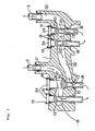
- numeral 10 designates a seal, which is interposed in portions in Fig. 1 which are blacked solidly, for example, portions where no threaded portion is formed of the fitting portion of the steam chamber unit 1 into which the bolt-like member 4 is fitted, connection portions between the bolt-like member 4 and the steam inlet nozzle 15 or the steam outlet nozzle 16, connection portions between the steam chamber unit 1 and the inlet pipe 2 or the outlet pipe 3, etc. and the construction is made such that there occurs no substantial leakage of the cooling steam from the cooling passage from the inlet pipe 2 to the outlet pipe 3.
Landscapes
- Engineering & Computer Science (AREA)
- Mechanical Engineering (AREA)
- General Engineering & Computer Science (AREA)
- Turbine Rotor Nozzle Sealing (AREA)
Claims (4)
- Unité (1) d'un seul tenant formant chambre à vapeur pour une turbine à gaz du type à refroidissement par de la vapeur comprenant :un passage (31) d'alimentation en vapeur pour y faire passer de la vapeur de refroidissement, un passage (32) de communication pour de la vapeur pour y envoyer la vapeur de refroidissement d'une aube (5) directrice d'un étage avant à une aube (6) directrice d'un étage subséquent et un passage (33) de récupération de la vapeur pour y récupérer la vapeur de refroidissement après qu'elle a refroidi une pluralité des étages d'aubes directrices, les passages (31, 32, 33) pour de la vapeur formant un passage de refroidissement consécutif s'étendant dans l'unité (1) formant chambre à vapeur ; etune pluralité de conduits de ramification formés respectivement dans un élément inséré par un côté circonférentiel extérieur de l'unité (1) formant chambre à vapeur dans des parties d'adaptation de l'unité (1) formant chambre à vapeur, et ayant respectivement une ouverture (13) communiquant avec les passages (31, 32, 33) respectifs pour de la vapeur et étant aptes à relier les passages (31, 32, 33) respectifs pour de la vapeur à des passages (17) pour de la vapeur de refroidissement des aubes (5, 6) directrices.
- Unité (1) d'un seul tenant formant chambre à vapeur pour une turbine à gaz du type à refroidissement par de la vapeur suivant la revendication 1, dans laquelle les conduits de ramification sont formés respectivement dans un élément (4) creux analogue à un boulon ayant une partie (41) filetée, l'élément (4) creux analogue à un boulon pouvant être fixé à la partie respective d'adaptation de l'unité (1) formant chambre à vapeur par l'intermédiaire de la partie (41) filetée.
- Unité (1) d'un seul tenant formant chambre à vapeur pour une turbine à gaz de type à refroidissement par de la vapeur suivant la revendication 1, dans laquelle le conduit de ramification est formé dans un élément (18) creux analogue à un conduit ayant une bride (34) à sa partie supérieure, l'élément (18) analogue à un conduit pouvant être fixé à la partie respective d'adaptation de l'unité (1) formant chambre à vapeur en fixant la bride (34) à une partie de surface circonférentielle extérieure dans la direction radiale de turbine de l'unité (1) formant chambre à vapeur.
- Unité (1) d'un seul tenant formant chambre à vapeur pour une turbine à gaz de type à refroidissement par de la vapeur suivant la revendication 1, 2 ou 3, comprenant en outre un conduit (11) d'alimentation en vapeur communiquant avec le passage (31) d'alimentation en vapeur pour y envoyer une partie de la vapeur de refroidissement à une chambre de combustion et un conduit (12) de récupération de vapeur communiquant avec le passage (32) de communication pour de la vapeur afin d'y récupérer la vapeur de refroidissement provenant de la chambre de combustion.
Applications Claiming Priority (2)
| Application Number | Priority Date | Filing Date | Title |
|---|---|---|---|
| JP35495397A JP3564290B2 (ja) | 1997-12-24 | 1997-12-24 | 蒸気冷却型ガスタービン |
| JP35495397 | 1997-12-24 |
Publications (3)
| Publication Number | Publication Date |
|---|---|
| EP0926323A2 EP0926323A2 (fr) | 1999-06-30 |
| EP0926323A3 EP0926323A3 (fr) | 2001-01-24 |
| EP0926323B1 true EP0926323B1 (fr) | 2004-06-16 |
Family
ID=18441011
Family Applications (1)
| Application Number | Title | Priority Date | Filing Date |
|---|---|---|---|
| EP98123914A Expired - Lifetime EP0926323B1 (fr) | 1997-12-24 | 1998-12-16 | Chambre de vapeur pour une turbine à gaz refroidi par vapeur |
Country Status (5)
| Country | Link |
|---|---|
| US (1) | US6230483B1 (fr) |
| EP (1) | EP0926323B1 (fr) |
| JP (1) | JP3564290B2 (fr) |
| CA (1) | CA2256597C (fr) |
| DE (1) | DE69824538T2 (fr) |
Families Citing this family (11)
| Publication number | Priority date | Publication date | Assignee | Title |
|---|---|---|---|---|
| JP2002155703A (ja) * | 2000-11-21 | 2002-05-31 | Mitsubishi Heavy Ind Ltd | ガスタービン静翼−翼環間蒸気通路のシール構造 |
| JP2002309903A (ja) * | 2001-04-10 | 2002-10-23 | Mitsubishi Heavy Ind Ltd | ガスタービンの蒸気配管構造 |
| JP2002309906A (ja) * | 2001-04-11 | 2002-10-23 | Mitsubishi Heavy Ind Ltd | 蒸気冷却型ガスタービン |
| ITMI20021465A1 (it) | 2002-07-03 | 2004-01-05 | Nuovo Pignone Spa | Dispositivo di schermatura termica di facile montaggio per un accoppiamento tra una tubazione di raffreddamento ed una foratura passante rea |
| EP1389690B1 (fr) * | 2002-08-16 | 2007-01-03 | Siemens Aktiengesellschaft | Vis intérieurement refroidissable |
| FR2871844B1 (fr) * | 2004-06-17 | 2006-09-29 | Snecma Moteurs Sa | Montage etanche d'un distributeur de turbine haute pression sur une extremite d'une chambre de combustion dans une turbine a gaz |
| US8079803B2 (en) * | 2008-06-30 | 2011-12-20 | Mitsubishi Heavy Industries, Ltd. | Gas turbine and cooling air supply structure thereof |
| US8616834B2 (en) * | 2010-04-30 | 2013-12-31 | General Electric Company | Gas turbine engine airfoil integrated heat exchanger |
| JP5055451B1 (ja) * | 2011-03-31 | 2012-10-24 | 三菱重工業株式会社 | 低圧蒸気タービン |
| US9328623B2 (en) * | 2011-10-05 | 2016-05-03 | General Electric Company | Turbine system |
| US11125160B2 (en) * | 2015-12-28 | 2021-09-21 | General Electric Company | Method and system for combination heat exchanger |
Family Cites Families (9)
| Publication number | Priority date | Publication date | Assignee | Title |
|---|---|---|---|---|
| US4438625A (en) * | 1978-10-26 | 1984-03-27 | Rice Ivan G | Reheat gas turbine combined with steam turbine |
| US5253976A (en) * | 1991-11-19 | 1993-10-19 | General Electric Company | Integrated steam and air cooling for combined cycle gas turbines |
| US5480281A (en) * | 1994-06-30 | 1996-01-02 | General Electric Co. | Impingement cooling apparatus for turbine shrouds having ducts of increasing cross-sectional area in the direction of post-impingement cooling flow |
| US5640840A (en) * | 1994-12-12 | 1997-06-24 | Westinghouse Electric Corporation | Recuperative steam cooled gas turbine method and apparatus |
| US5685693A (en) * | 1995-03-31 | 1997-11-11 | General Electric Co. | Removable inner turbine shell with bucket tip clearance control |
| JP3238299B2 (ja) * | 1995-04-17 | 2001-12-10 | 三菱重工業株式会社 | ガスタービン |
| JPH1061457A (ja) * | 1996-08-27 | 1998-03-03 | Mitsubishi Heavy Ind Ltd | 複合サイクル発電プラント用ガスタービン |
| WO1999040305A1 (fr) * | 1996-08-27 | 1999-08-12 | Mitsubishi Heavy Industries, Ltd. | Turbine a gaz pour centrale a cycle mixte |
| US5819525A (en) * | 1997-03-14 | 1998-10-13 | Westinghouse Electric Corporation | Cooling supply manifold assembly for cooling combustion turbine components |
-
1997
- 1997-12-24 JP JP35495397A patent/JP3564290B2/ja not_active Expired - Fee Related
-
1998
- 1998-12-16 DE DE69824538T patent/DE69824538T2/de not_active Expired - Lifetime
- 1998-12-16 EP EP98123914A patent/EP0926323B1/fr not_active Expired - Lifetime
- 1998-12-17 CA CA002256597A patent/CA2256597C/fr not_active Expired - Fee Related
- 1998-12-23 US US09/220,686 patent/US6230483B1/en not_active Expired - Lifetime
Also Published As
| Publication number | Publication date |
|---|---|
| CA2256597A1 (fr) | 1999-06-24 |
| JP3564290B2 (ja) | 2004-09-08 |
| US6230483B1 (en) | 2001-05-15 |
| DE69824538T2 (de) | 2005-06-30 |
| DE69824538D1 (de) | 2004-07-22 |
| EP0926323A2 (fr) | 1999-06-30 |
| JPH11182205A (ja) | 1999-07-06 |
| EP0926323A3 (fr) | 2001-01-24 |
| CA2256597C (fr) | 2001-12-11 |
Similar Documents
| Publication | Publication Date | Title |
|---|---|---|
| US5819525A (en) | Cooling supply manifold assembly for cooling combustion turbine components | |
| RU2179245C2 (ru) | Газотурбинный двигатель с системой воздушного охлаждения лопаток турбины и способ охлаждения полой профильной части лопатки | |
| EP0911486B1 (fr) | Refroidissement d'une aube de guidage pour une turbine à gaz | |
| US6772581B2 (en) | Gas turbine cooling passages for blade rings, combustor transition piece connecting portions and stationary blades | |
| US6422817B1 (en) | Cooling circuit for and method of cooling a gas turbine bucket | |
| US6823676B2 (en) | Mounting for a CMC combustion chamber of a turbomachine by means of flexible connecting sleeves | |
| EP0926323B1 (fr) | Chambre de vapeur pour une turbine à gaz refroidi par vapeur | |
| EP1130237A2 (fr) | Circuit de refroidissement fermé pour aubage de turbine | |
| KR20030035961A (ko) | 터빈용 내부 슈라우드 조립체, 터빈 슈라우드 조립체용세그먼트 및 냉각 공기 배기 방법 | |
| JP2004108768A (ja) | ガスタービンの燃焼器 | |
| EP0900919A2 (fr) | Turbine à gaz refroidi par vapeur | |
| US6341937B1 (en) | Steam turbine with an improved cooling system for the casing | |
| US6220036B1 (en) | Cooling structure for combustor tail pipes | |
| US7870739B2 (en) | Gas turbine engine curved diffuser with partial impingement cooling apparatus for transitions | |
| US6422810B1 (en) | Exit chimney joint and method of forming the joint for closed circuit steam cooled gas turbine nozzles | |
| SU1673734A1 (ru) | Устройство дл охлаждени ротора паровой турбины | |
| US5062262A (en) | Cooling of turbine nozzles | |
| CN100394110C (zh) | 燃气轮机 | |
| JP3813845B2 (ja) | ガスタービン装置 | |
| RU2037051C1 (ru) | Устройство для охлаждения элементов проточной части паровой турбины | |
| JP2003148109A (ja) | 蒸気タービン車室の変形量調整装置 | |
| JP2009287522A (ja) | ブリードエア冷却器アセンブリおよびこれを取付ける方法、並びにブリードエア冷却器アセンブリのキット |
Legal Events
| Date | Code | Title | Description |
|---|---|---|---|
| PUAI | Public reference made under article 153(3) epc to a published international application that has entered the european phase |
Free format text: ORIGINAL CODE: 0009012 |
|
| 17P | Request for examination filed |
Effective date: 19990113 |
|
| AK | Designated contracting states |
Kind code of ref document: A2 Designated state(s): CH DE FR GB IT LI |
|
| AX | Request for extension of the european patent |
Free format text: AL;LT;LV;MK;RO;SI |
|
| PUAL | Search report despatched |
Free format text: ORIGINAL CODE: 0009013 |
|
| AK | Designated contracting states |
Kind code of ref document: A3 Designated state(s): AT BE CH CY DE DK ES FI FR GB GR IE IT LI LU MC NL PT SE |
|
| AX | Request for extension of the european patent |
Free format text: AL;LT;LV;MK;RO;SI |
|
| RIC1 | Information provided on ipc code assigned before grant |
Free format text: 7F 02C 7/16 A, 7F 01D 5/18 B, 7F 02C 7/18 B |
|
| AKX | Designation fees paid |
Free format text: CH DE FR GB IT LI |
|
| 17Q | First examination report despatched |
Effective date: 20021024 |
|
| RTI1 | Title (correction) |
Free format text: STEAM CHAMBER FOR A STEAM COOLED GAS TURBINE |
|
| GRAP | Despatch of communication of intention to grant a patent |
Free format text: ORIGINAL CODE: EPIDOSNIGR1 |
|
| RTI1 | Title (correction) |
Free format text: STEAM CHAMBER FOR A STEAM COOLED GAS TURBINE |
|
| RTI1 | Title (correction) |
Free format text: STEAM CHAMBER FOR A STEAM COOLED GAS TURBINE |
|
| RIN1 | Information on inventor provided before grant (corrected) |
Inventor name: ENDO, TADAYOSHIC/O KORYO ENGINEERING CO., LTD. Inventor name: SAKON, TOSHIOC/O MITSUBISHI HEAVY INDUSTRIES LTD. |
|
| RTI1 | Title (correction) |
Free format text: STEAM CHAMBER FOR A STEAM COOLED GAS TURBINE |
|
| GRAS | Grant fee paid |
Free format text: ORIGINAL CODE: EPIDOSNIGR3 |
|
| GRAA | (expected) grant |
Free format text: ORIGINAL CODE: 0009210 |
|
| AK | Designated contracting states |
Kind code of ref document: B1 Designated state(s): CH DE FR GB IT LI |
|
| PG25 | Lapsed in a contracting state [announced via postgrant information from national office to epo] |
Ref country code: LI Free format text: LAPSE BECAUSE OF FAILURE TO SUBMIT A TRANSLATION OF THE DESCRIPTION OR TO PAY THE FEE WITHIN THE PRESCRIBED TIME-LIMIT Effective date: 20040616 Ref country code: IT Free format text: LAPSE BECAUSE OF FAILURE TO SUBMIT A TRANSLATION OF THE DESCRIPTION OR TO PAY THE FEE WITHIN THE PRESCRIBED TIME-LIMIT;WARNING: LAPSES OF ITALIAN PATENTS WITH EFFECTIVE DATE BEFORE 2007 MAY HAVE OCCURRED AT ANY TIME BEFORE 2007. THE CORRECT EFFECTIVE DATE MAY BE DIFFERENT FROM THE ONE RECORDED. Effective date: 20040616 Ref country code: FR Free format text: LAPSE BECAUSE OF NON-PAYMENT OF DUE FEES Effective date: 20040616 Ref country code: CH Free format text: LAPSE BECAUSE OF FAILURE TO SUBMIT A TRANSLATION OF THE DESCRIPTION OR TO PAY THE FEE WITHIN THE PRESCRIBED TIME-LIMIT Effective date: 20040616 |
|
| REG | Reference to a national code |
Ref country code: GB Ref legal event code: FG4D |
|
| REG | Reference to a national code |
Ref country code: CH Ref legal event code: EP |
|
| REF | Corresponds to: |
Ref document number: 69824538 Country of ref document: DE Date of ref document: 20040722 Kind code of ref document: P |
|
| PG25 | Lapsed in a contracting state [announced via postgrant information from national office to epo] |
Ref country code: GB Free format text: LAPSE BECAUSE OF NON-PAYMENT OF DUE FEES Effective date: 20041216 |
|
| REG | Reference to a national code |
Ref country code: CH Ref legal event code: PL |
|
| PLBE | No opposition filed within time limit |
Free format text: ORIGINAL CODE: 0009261 |
|
| STAA | Information on the status of an ep patent application or granted ep patent |
Free format text: STATUS: NO OPPOSITION FILED WITHIN TIME LIMIT |
|
| 26N | No opposition filed |
Effective date: 20050317 |
|
| EN | Fr: translation not filed | ||
| GBPC | Gb: european patent ceased through non-payment of renewal fee |
Effective date: 20041216 |
|
| REG | Reference to a national code |
Ref country code: DE Ref legal event code: R082 Ref document number: 69824538 Country of ref document: DE Representative=s name: PATENTANWAELTE HENKEL, BREUER & PARTNER, DE Ref country code: DE Ref legal event code: R081 Ref document number: 69824538 Country of ref document: DE Owner name: MITSUBISHI HITACHI POWER SYSTEMS, LTD., YOKOHA, JP Free format text: FORMER OWNER: MITSUBISHI HEAVY INDUSTRIES, LTD., TOKYO, JP |
|
| PGFP | Annual fee paid to national office [announced via postgrant information from national office to epo] |
Ref country code: DE Payment date: 20151208 Year of fee payment: 18 |
|
| REG | Reference to a national code |
Ref country code: DE Ref legal event code: R119 Ref document number: 69824538 Country of ref document: DE |
|
| PG25 | Lapsed in a contracting state [announced via postgrant information from national office to epo] |
Ref country code: DE Free format text: LAPSE BECAUSE OF NON-PAYMENT OF DUE FEES Effective date: 20170701 |